A contactor is one of the main control elements of an electric motor, which serves as a disconnect switch and also performs the work of a soft starter or frequency converter. But the most ideal option is to control the electric motor using a contactor, because it makes it possible to implement remote control. One of the main advantages of contactors is switching durability, several thousand operations.
For a contactor, it is extremely important to have high-quality characteristics of power and control circuits. To select a contactor for switching electrical equipment, it is necessary to provide certain information characterizing the control circuits and power circuits; the passport data contains the following information:
For control circuits:
- Control contact type and frequency for AC circuits.
- Rated voltage and control voltage.
For power circuits:
- Operating voltage, nominal value. This indicator is equal to the voltage between phases and determines, along with the closing and breaking capacity, operating mode and starting characteristics, the operating parameters of the use of circuits.
- Operating current, its rated value for which the contactor is designed or rated power. These indicators serve to determine the operating conditions of the electric motor; if the contactor is designed to directly control the electric motor, additional parameters such as maximum power can be entered.
It is worth paying attention to additional information, such as:
- Recommended operating modes and intermittent duty class that determine the operating cycles of the equipment.
- The maximum amount of current that the contactor can switch with a guaranteed probability.
Magnetic starter: purpose, device, connection diagrams
It is better to supply power to electric motors through magnetic starters (also called contactors). Firstly, they provide protection against inrush currents. Secondly, the normal connection diagram for a magnetic starter contains controls (buttons) and protection (thermal relays, self-retaining circuits, electrical interlocks, etc.). Using these devices, you can start the engine in the opposite direction (reverse) by pressing the corresponding button. All this is organized using diagrams, and they are not very complicated and can be assembled independently.
Contactor coils in the CMM shop
KMM company specialists are ready to advise you on which contactor coil is suitable for your modification of the device. To do this, call us by phone and tell us the model of the contactor for which the coil is being selected. If necessary, we will also advise you on the details of connecting the coil or replacing it. Here, for example, it is important to check that the moving parts of the electromagnet do not touch the insulation of the coil, and if there is contact, adjust the movement of the moving parts or change the position of the coil so that they do not touch.
There are other details that we will also enlighten you about once you become our customer. Order a contactor coil by phone or come to our store in Moscow, on the territory of the Mitinsky Radio Market shopping complex - this will be the beginning of our long-term mutually beneficial cooperation!
Purpose and device
Magnetic starters are built into power networks to supply and disconnect power. They can work with alternating or direct voltage. The work is based on the phenomenon of electromagnetic induction; there are working (power is supplied through them) and auxiliary (signal) contacts. For ease of use, Stop, Start, Forward, Back buttons are added to the magnetic starter switching circuits.
This is what a magnetic starter looks like
Magnetic starters can be of two types:
- With normally closed contacts. Power is supplied to the load constantly and is turned off only when the starter is triggered.
- With normally open contacts. Power is supplied only while the starter is running.
The second type is more widely used - with normally open contacts. After all, basically, devices should work for a short period of time, the rest of the time they should be at rest. Therefore, next we will consider the principle of operation of a magnetic starter with normally open contacts.
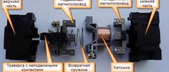
Composition and purpose of parts
The basis of a magnetic starter is an inductance coil and a magnetic circuit. The magnetic core is divided into two parts. Both of them have the shape of the letter “W”, installed in a mirror image. The lower part is stationary, its middle part is the core of the inductor. The parameters of the magnetic starter (the maximum voltage with which it can operate) depend on the inductor. There may be starters of small ratings - 12 V, 24 V, 110 V, and the most common - 220 V and 380 V.
Magnetic starter (contactor) device
The upper part of the magnetic circuit is movable, with movable contacts attached to it. The load is connected to them. Fixed contacts are fixed to the starter body and are supplied with supply voltage. In the initial state, the contacts are open (due to the elastic force of the spring that holds the upper part of the magnetic circuit), power is not supplied to the load.
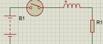
Principle of operation
In the normal state, the spring lifts the upper part of the magnetic circuit, the contacts are open. When power is applied to a magnetic starter, the current flowing through the inductor generates an electromagnetic field. Compressing the spring, it attracts the moving part of the magnetic circuit, the contacts close (the picture on the right). Through closed contacts, power is supplied to the load, it is in operation.
Operating principle of a magnetic starter (contactor)
When the power to the magnetic starter is turned off, the electromagnetic field disappears, the spring pushes the upper part of the magnetic circuit up, the contacts open, and power is not supplied to the load.
AC or DC voltage can be supplied through a magnetic starter. Only its size is important - it should not exceed the nominal value specified by the manufacturer. For alternating voltage the maximum is 600 V, for direct voltage - 440 V.
Two main types of contactors
Contactors are divided into two types and can be single or double.
Twin contactors are used for heavy duty applications.
A single contactor contains in its design an electromagnetic device that serves to effectively extinguish the electric arc. It is recommended for DC circuits and severe operating conditions such as railway equipment, hydroelectric power plants, induction furnaces, etc.
The contactor must extinguish the arc that occurs when the electrical circuit breaks. In this case, the arc should not be too short (fast) so as not to cause overvoltage in the network and not long so as not to contribute to the destruction of the materials that make up the contactor. The resistance of the arc is directly dependent on the number of free electrons present in the plasma. Ferromagnetic elements that make up the arc suppression chambers and placed in the arc area are necessarily present in the design of the poles. They must turn the arc in the desired direction, this is the so-called magnetic explosion, so they will help cool the environment and the contact connection after the arc is extinguished. To protect against overload, contactors are combined with electronic or thermal overload relays.
Rice. No. 2. Contactor device.
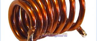
Coil
The contactor coil creates an electromagnetic field in which the moving part of the contactor moves, completing the electrical circuit. Power to the coil comes from AC and DC mains.
Coil AC power supply
In the case of AC power, its value is determined by the impedance of the coil. If the magnetic gap when the coil is turned on is large, the inductance of the coil has a small value, the total resistance will be minimal. The current passing through the coil is maximum and is limited by the resistance value. The amount of load current dictates the pulling force required to turn on the contactor.
When a magnetic circuit closes, its magnetic resistance drops, at the same time its total resistance increases many times, and the current decreases by at least 10 times. The current in the coil decreases with increasing total resistance value, which is caused by decreasing the gap in the contactor, but at the same time it should be enough to keep the electromagnetic coil in the closed state.
DC coil power supply
For DC networks, additional resistance (usually a resistor) is included in the coil supply circuit.
Automation systems use specially designed contactors with electromagnets with low power consumption. They allow direct connection of equipment; these devices are controlled from a discrete output in a direct way. To perform this function, the contactor is equipped with a special electromagnet.
Rice. No. 3. Low power electromagnet circuit.
Additional contact system
The main function of the auxiliary contacts is self-blocking, mutual blocking and interlocking of contacts, as well as indicating the status of the contactor.
Basic modifications of additional contacts
There are three types:
- NO (NO) – normally open contacts (the open state corresponds to an open contact), the closed state – corresponds to the supply of supply voltage to the electromagnet.
- NC (NC) – normally closed contacts: the closed state corresponds to the open position of the contactor, the open contact – power supply to the electromagnet.
- Changeover contacts NO/NC. If the contactor is not receiving power, its contacts will be in the open or closed state. After voltage is applied, their state switches to the opposite.
The additional contact system is equipped with a time delay that can be used after opening or closing the contactor. Time is adjustable.
Connection diagram for a starter with a 220 V coil
In any magnetic starter connection diagram there are two circuits. One power line through which power is supplied. The second is a signal one. This circuit controls the operation of the device. They need to be considered separately - it’s easier to understand the logic.
At the top of the magnetic starter housing there are contacts to which the power for this device is connected. The usual designation is A1 and A2. If the coil is 220 V, 220 V is supplied here. It makes no difference where to connect “zero” and “phase”. But more often the “phase” is supplied to A2, since here this output is usually duplicated in the lower part of the case and quite often it is more convenient to connect here.
Connecting power to the magnetic starter
Below on the case there are several contacts labeled L1, L2, L3. The power supply for the load is connected here. Its type is not important (constant or alternating), it is important that the rating is not higher than 220 V. Thus, voltage from a battery, wind generator, etc. can be supplied through a starter with a 220 V coil. It is removed from contacts T1, T2, T3.
Purpose of magnetic starter sockets
The simplest scheme
If you connect a power cord (control circuit) to pins A1 - A2, apply 12 V voltage from the battery to L1 and L3, and lighting devices (power circuit) to pins T1 and T3, we get a lighting circuit operating on 12 V. This is only one of the options for using a magnetic starter.
But more often, these devices are used to supply power to electric motors. In this case, 220 V is also connected to L1 and L3 (and the same 220 V is removed from T1 and T3).
The simplest diagram for connecting a magnetic starter - without buttons
The disadvantage of this scheme is obvious: to turn the power off and on, you will have to manipulate the plug - remove/insert it into the socket. The situation can be improved if you install an automatic machine in front of the starter and turn on/off the power supply to the control circuit with its help. The second option is to add buttons to the control circuit - Start and Stop.
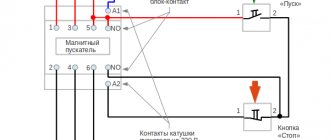
Diagram with “Start” and “Stop” buttons
When connected via buttons, only the control circuit changes. The strength remains unchanged. The entire connection diagram of the magnetic starter changes slightly.
The buttons can be in a separate case, or in one. In the second version, the device is called a “push-button post”. Each button has two inputs and two outputs. The “start” button has normally open contacts (power is supplied when it is pressed), the “stop” button has normally closed contacts (the circuit breaks when pressed).
Contactor coils – high-quality components for high-power power circuits
If a contactor that has served well for several years refuses to work, perhaps the reason is a faulty coil? There can be many reasons for coil breakdowns, for example, an increase in current in it and overheating due to the armature not being switched on or mechanical breakdowns of another nature, sticking of the coil, etc. One way or another, since the contactor coil is the basic component of this device, it should be replaced at the first appearance of malfunctions.
The assortment of the CMM store includes various coils for contactors of different types - both domestic and foreign. We sell both current coils, consisting of a small number of turns of wire, the area of which corresponds to the strength of the passing current, and voltage coils, consisting of a large number of turns of wire with a small cross-section.
Connection to a three-phase network via a contactor with a 220 V coil
Through a standard magnetic starter operating from 220 V, three-phase power can be connected. This magnetic starter connection diagram is used with asynchronous motors. There are no differences in the control circuit. One of the phases and “zero” are connected to contacts A1 and A2. The phase wire goes through the “start” and “stop” buttons, and a jumper is also placed on NO13 and NO14.
How to connect a 380V induction motor via a contactor with a 220V coil
The differences in the power circuit are minor. All three phases are supplied to L1, L2, L3, and a three-phase load is connected to outputs T1, T2, T3. In the case of a motor, a thermal relay (P) is often added to the circuit, which will prevent the motor from overheating. The thermal relay is placed in front of the electric motor. It controls the temperature of two phases (placed on the most loaded phases, the third), opening the power circuit when critical temperatures are reached. This magnetic starter connection diagram is used often and has been tested many times. See the following video for assembly procedure.
Contactor design
The contactor consists of several main parts:
- pole;
- coil;
- additional contacts.
Poles.
Rice. No. 1 Type of double and single contactor.
These elements are used to make and break current in a power circuit. The overall size of the pole depends on the current for which the contactor is designed; the pole allows for continuous operation without a critical increase in the temperature threshold. The element consists of a moving part and a fixed fixed contact. There is a spring on the moving part that exerts pressure on the closing contacts. Special silver plating and appropriate innovative processing contribute to longevity, durability and mechanical strength.
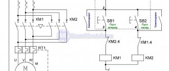
Reverse motor connection diagram
Some devices require the motor to rotate in both directions to operate. The direction of rotation changes when the phases are transferred (two arbitrary phases must be swapped). The control circuit also requires a push-button station (or separate buttons) “stop”, “forward”, “backward”.
The connection diagram for a magnetic starter for engine reversal is assembled on two identical devices. It is advisable to find ones that have a pair of normally closed contacts. The devices are connected in parallel - to reverse the rotation of the motor, the phases on one of the starters are swapped. The outputs of both are fed to the load.
Signal circuits are somewhat more complex. The “stop” button is general. Next to it is a “forward” button, which connects to one of the starters, and a “back” button to the second. Each of the buttons must have bypass circuits (“self-catch”) so that there is no need to keep one of the buttons pressed all the time (jumpers are installed on NO13 and NO14 on each of the starters).
Connection diagram for a reverse motor using a magnetic starter
To avoid the possibility of power being supplied through both buttons, an electrical interlock is implemented. To do this, after the “forward” button, power is supplied to the normally closed contacts of the second contactor. The second contactor is connected in the same way - through the normally closed contacts of the first.
If the magnetic starter does not have normally closed contacts, they can be added by installing an attachment. When installed, the attachments are connected to the main unit and their contacts work simultaneously with others. That is, while power is supplied through the “forward” button, an open normally closed contact will not allow reverse motion to be activated. To change direction, press the “stop” button, after which you can turn on the reverse by pressing “back”. The reverse switching occurs in the same way - through “stop”.
Contactor selection
When choosing a contactor to control an electric motor, the following requirements are used:
- Operating current and shutdown mode.
- The type of electric motor (load) is: resistance, squirrel cage or slip ring motor.
- Conditions that affect the opening or closing of contacts are: the electric motor is running or stopped, starting the electric motor or braking by back-on and other operations.
When selecting a contactor, limitations that are not described in the standard operating instructions are taken into account. This is the ambient temperature, humidity, geographical location, altitude or proximity to the sea. Difficulty in maintenance can also play a decisive role in the selection of a contactor, this condition being influenced by the durability of the device or its reliability.
Write comments, additions to the article, maybe I missed something. Take a look at the site map, I will be glad if you find anything else useful on my site.
Similarities and differences between contactors and starters
Both devices serve to close and open the circuit as needed. Their design is based on an electromagnet; they operate on both alternating and direct current. Equipped with power, or main, as well as signal, or auxiliary, contacts.
The difference lies in the degree of protection of the devices. Contactors are equipped with a chamber for extinguishing the arc. Due to this feature, they are used in circuits with higher power than starters. In addition, the device itself is more massive due to arc suppression chambers. The maximum permissible current for starters is up to 10 amperes.
The starters are made in a plastic case and are equipped with eight contacts - six for powering a three-phase motor, and two for providing it with power after the “start” button is stopped pressing. They are used both to power electric motors and devices for which this circuit is suitable.
Contactors are often manufactured without a housing, so during operation it is necessary to provide them with a protective casing that protects it from moisture and contamination, and electric shock to people.
What is a contactor coil?
Essentially, a contactor coil is a winding of insulated wire with or without a plastic or cardboard frame, which provides terminals for connection to power circuits. This component of the contactor serves to create the magnetic flux necessary for the operation of connected equipment, such as electric motors. The stability and safety of the power circuit largely depends on the coil.
Coils are used in various electrical devices - contactors, starters, relays, circuit breaker releases, etc., so there are a huge variety of them. In addition, even coils of the same size can have different voltages, both AC and DC. The operation of the entire circuit depends on how correctly the contactor coil is selected. When choosing, it is important to consider compliance with the mains voltage, as well as other parameters.
220 volt network
When powered from a 220 volt single-phase network, the connection is made through the terminals, which are usually designated A1 and A2. They are located at the top of the starter housing. When a wire with a plug is connected to them, the device is connected to the network. The terminals marked L1, L2, L3 are supplied with any voltage removed from contacts T1, T2 and T3.
When connecting to a device, zero and phase can be easily transferred, this is not important. Typically, power is supplied through a temperature or light level sensor, for example, when connecting the starter to autonomous heating or street lighting.
Start and stop buttons
When starting and stopping the engine using a starter, it is convenient to connect a device with buttons connected in series with the device.
To ensure that the engine does not stop working after pressing the “start” button, self-retaining is introduced into the circuit due to the terminals paralleled with the “start”. Thanks to them, the engine runs after the “start” button is no longer pressed, until the stop button is pressed.
Voltage is supplied to the motor through any contact marked with the letter L, and it is removed from the corresponding contact under the letter T. This connection diagram is valid for a single-phase network.
Starter control buttons
In general, you will need two buttons: one to turn it on and one to turn it off. Please note that they use contacts with different purposes to control the starter. For the “Stop” button they are normally closed, that is, if the button is not pressed, the group of contacts is closed, and opens when the button is activated. The Start button is the opposite.
These devices can either contain only a specific element needed for operation, or be universal, including one closed and one open contact. In this case, you need to choose the right one.
Manufacturers usually provide their products with symbols that make it possible to determine the purpose of a particular contact group. The stop button is usually painted red. The launcher color is traditionally black, but green is welcome, which corresponds to the “On” or “Turn on” signal. Such buttons are mainly used on cabinet doors and machine control panels.
For remote control, push-button stations are used, containing two buttons in one housing. The station is connected to the starter installation location using a control cable. It must have at least three cores, the cross-section of which may be small.
The simplest working circuit of a starter with a thermal relay
Magnetic switch
Now about what you should pay attention to when examining the starter itself before connecting it. The most important thing is the voltage of the control coil, which is indicated either on it itself or nearby. If the inscription reads 220 V AC (or there is an AC icon next to 220), then a phase and a zero are required for the control circuit to operate.
Watch an interesting video about the operation of a magnetic starter below:
If it is 380 V AC (the same alternating current), then the starter will be controlled by two phases. In the process of describing the operation of the control circuit, it will become clear what the difference is.
With any other voltage values, the presence of a direct current sign or the letters DC, it will not be possible to connect the product to the network. It is intended for other circuits.
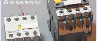
We will also need to use an additional contact of the starter, called a block contact. For most devices, it is marked with the numbers 13NO (13NO, simply 13) and 14NO (14NO, 14).
The letters NO mean “normally open”, that is, it closes only when the starter is pulled in, which can be checked with a multimeter if desired. There are starters that have normally closed additional contacts; they are not suitable for the control circuit under consideration.
Power contacts are designed to connect the load, which they control.
Their markings vary from manufacturer to manufacturer, but there are no difficulties in identifying them. So, we attach the starter to the surface or DIN rail in the place of its permanent location, lay the power and control cables, and begin the connection.
Contactors and magnetic starters
To bookmarks
Introduction
At the beginning of this article, I would like to immediately determine what the difference is between a contactor and a magnetic starter, since this question often baffles even the most experienced electrical specialists, while many believe that the difference between them lies in their design, overall dimensions or the value of the switched (rated) current, but this is not so. GOST 30011.4.1-96 will help us understand this issue, which provides the following definitions:
A contactor is a switching device with a single rest position, not manually operated, capable of switching on, carrying and breaking currents under normal circuit conditions, including during operating overloads.
A starter is a combination of all the switching devices needed to start and stop the motor, with overload protection.
As follows from the definitions above, a contactor is a device designed to switch (turn on/off) any loads, i.e. any loads, while starters are a set of devices designed to control a specific electric motor, as well as providing its protection against overloads, while the contactors themselves are part of the starters:
As you can see in the picture above, the starter includes: a contactor - to turn the electric motor on and off, a thermal relay - to protect the electric motor from overloads, buttons - to control the contactor, all of the above devices are placed in a common housing.
Also, according to the same GOST 30011.4.1-96, starters come in the following types:
Direct-acting starter - A starter that supplies mains voltage to the motor terminals in a single step. Reversing starter - A starter designed to change the direction of rotation of a motor by switching its supply connections without necessarily stopping the motor. Bidirectional Starter - A starter designed to change the direction of rotation of a motor by switching its supply connections only when the motor is stopped.
Thus, a direct-acting starter is designed to start, stop and protect the electric motor, while a reversing starter, in addition to all of the above, allows you to change the direction of rotation of the motor.
As you can see in the picture above, the reversible magnetic starter includes two contactors; switching between them changes the phase sequence, which leads to a change in the direction of rotation of the electric motor. (For more information about changing the direction of rotation of the electric motor and the operating diagram of the reversing starter, see here.)
There are also so-called modular contactors - these are compact contactors designed for installation on a DIN rail, otherwise their design and operating principle are the same as those of conventional contactors.
Now, having understood the concepts of contactor and starter, let’s begin to study the principle of their operation.
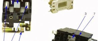
Design and principle of operation of the contactor
As can be seen in the picture above, an electromagnetic contactor consists of the following main elements: a magnetic circuit consisting, in turn, of moving and stationary parts, an electric coil, power contacts designed to turn on and off the load, which include moving contacts that are attached to the moving parts of the magnetic circuit and fixed contacts that are attached to the upper part of the contactor body, block contacts intended for use in control circuits, as well as a spring that ensures that the power contacts are maintained in an open state.
The contactor is controlled by applying voltage to an electric coil; when an electric current passes through it, an electromagnetic field is created flowing through the magnetic circuit, while the stationary part of the magnetic circuit together with the electric coil work as an electromagnet which, as can be seen in Fig. 2 above, overcoming the resistance of the spring, attracts the upper moving part of the magnetic circuit with moving contacts attached to it, thus closing the power contacts; when the voltage is removed from the contactor coil, the electromagnetic field disappears, ceasing to attract the moving part of the magnetic circuit, which, under the influence of a spring, returns to its original position, opening the power contacts.
Most modern contactors include only one block contact, but some control circuits require more of them; in this case, an additional attachment with several block contacts is installed on the magnetic starter:
As you can see in the picture above, this attachment (contact block) is installed on the upper part of the contactor connecting to its movable power contacts.
Note: See here for control diagrams for contactors (magnetic starters).
Selection of contactors (magnetic starters) and their characteristics.
The selection of contactors and magnetic starters is carried out according to their following technical characteristics:
1) The required category of application is determined by the type of switched load
In accordance with GOST 12434-83 and GOST R 50030.4.1-2002, there are the following categories (areas) of application of contactors (starters):
2) By rated current
Rated current is one of the main characteristics that determines the maximum current that the contactor can withstand for a long time, as well as ensure its switching (on/off).
The rated current of a starter (contactor) for an electric motor can be calculated using our online calculator or using the method given below.
There are the following standard values of rated currents of contactors (starters), in Amperes:
6.3; 10; 16; 25; 40; 63; 80; 100; 125; 160; 250; 400; 500 Ampere
Note: Modular contactors are available for rated currents up to 100 Amps.
Often, contactors and magnetic starters, depending on their rated current, are conventionally divided into the following values (from zero to seventh value):
The rated current of the starter for controlling the electric motor can be selected based on its power according to the following table:
You can also calculate the starter current yourself using the following method:
The rated current of the starter must be greater than or equal to the rated current of the motor:
I no. MP ⩾ I nom. engine
The rated current of the motor can be found from its passport data, or calculated using the formula:
Inom=P/√3Ucosφη
Where:
- P - Rated power of the electric motor (taken from the motor’s passport data or determined by calculation);
- U - Rated voltage (voltage to which the electric motor is connected);
- cosφ - Power factor - the ratio of active power to total power (taken from 0.75 to 0.9 depending on the power of the electric motor);
- η - Efficiency factor - the ratio of the electrical power consumed by the electric motor from the network to the mechanical power on the motor shaft (taken from 0.7 to 0.85 depending on the power of the electric motor);
You can also calculate the motor current using our online calculator.
The rated current of a contactor used not to control an electric motor is determined based on the current of the electrical network it controls:
I no. contactor ⩾ I calculated networks
The estimated network current can be determined using our online calculator, or you can calculate it yourself using the formula:
I network =(P network *K p )/cosφ , Ampere
Where:
- Pnetworks—the total power of all electrical equipment connected to the contactor, in kilowatts;
- Kp - conversion factor (For a single-phase network 220V: Kp=4.55; For a three-phase network 380V: Kp=1.52);
- cosφ is the power factor, taken to be from 0.95 to 1 for household electrical networks and from 0.75 to 0.85 for industrial electrical networks.
3) According to the rated voltage of the retractor coil
Coil voltage is a parameter characterizing the amount of voltage that must be applied to the terminals of the contactor coil for it to operate. Therefore, the nominal voltage of the coil also determines the voltage of the control circuit (voltage at the control buttons).
There are the following standard values for the rated voltage of contactor (starter) coils, Volts:
12, 24, 36, 48, 110, 127, 220, 380, 500, 660 Volts
The most commonly used are contactors with coils for 220 and 380 Volts, contactors with a coil for voltages of 48 Volts and below are usually used in rooms with increased danger (especially dangerous) in relation to electric shock to people, so that the voltage on the buttons of the control panels is safe .
4) According to rated insulation voltage
The rated insulation voltage of the contactor (starter) is the maximum network voltage for which the insulation of the contactor (starter) is designed; exceeding this value will lead to insulation breakdown and, as a consequence, failure of the contactor. Therefore, the rated voltage of the contactor must be greater than or equal to the mains voltage:
U nom. MP ⩾ U network
In networks with a voltage of 220/380 Volts, as a rule, contactors with a rated insulation voltage of 400 or 660 Volts are used.
Was this article useful to you? Or maybe you still have questions ? Write in the comments!
Didn’t find an article on the website on a topic that interests you regarding electrical engineering? Write to us here. We will definitely answer you.
↑ Up
5
https://elektroshkola.ru/kommutacionnye-apparaty/kontaktory-i-magnitnye-puskateli/
220 V starter control circuit
One wise man said: there are 44 schemes for connecting buttons to a magnetic starter, of which 3 work, and the rest do not. But there is only one correct one. Let's talk about it (see diagram below).
It is better to leave connecting the power circuits for later. This will make it easier to access the coil screws, which are always covered by the main circuit wires. To power the control circuits, we use one of the phase contacts, from which we send a conductor to one of the terminals of the “Stop” button.
This can be either a conductor or a cable core.
Two wires will go from the stop button: one to the “Start” button, the second to the block contact of the starter.
To do this, a jumper is placed between the buttons, and a cable core to the starter is added to one of them at the point where it is connected. There are also two wires from the second terminal of the “Start” button: one to the second terminal of the block contact, the second to terminal “A1” of the control coil.
When connecting buttons with a cable, the jumper is already placed on the starter, and the third core is connected to it. The second output from the coil (A2) is connected to the zero terminal. In principle, there is no difference in what order you connect the outputs of the buttons and the block contact. It is advisable to connect only the “A2” terminal of the control coil to the neutral conductor. Any electrician expects that zero potential will only be there.
Now you can connect the wires or cables of the power circuit, not forgetting that next to one of them at the input there is a wire to the control circuit. And only from this side is power supplied to the starter (traditionally - from above). Trying to connect buttons to the starter output will lead to nothing.
Connecting a thermal relay to the starter circuit
The thermal relay is used to protect the electric motor from overload. Of course, it is still protected by an automatic switch, but its thermal element is not enough for this purpose. And it cannot be adjusted exactly to the rated current of the motor. The operating principle of a thermal relay is the same as in a circuit breaker.
The current passes through the heating elements; if its value exceeds the specified value, the bimetallic plate bends and switches the contacts.
This is another difference from a circuit breaker: the thermal relay itself does not turn off anything. It simply gives a signal to turn off. Which needs to be used correctly.
The power contacts of the thermal relay allow you to connect it to the starter directly, without wires. To achieve this, each product range complements each other. For example, IEK produces thermal relays for its starters, ABB produces its own. And so it is with every manufacturer. But products from different companies do not fit together.
Thermal relays can also have two independent contacts: normally closed and normally open. We will need a closed one - as in the case of the “Stop” button. Moreover, functionally it will work the same way as this button: breaking the power supply circuit of the starter coil so that it falls off.
Now you need to embed the found contacts into the control circuit. In theory this can be done almost anywhere, but traditionally it is connected after the coil.
In the case described above, this will require sending a wire from pin “A2” to the contact of the thermal relay, and from its second contact to the place where the conductor was previously connected. In the case of control from 220 V, this is the zero bus; with 380 V, this is the phase on the starter. The thermal relay is not noticeable in most models.
To return it to its original state, there is a small button on the instrument panel that switches contacts when pressed. But this should not be done immediately, but let the relay cool down, otherwise the contacts will not engage. Before putting it into operation after installation, it is better to press the button, eliminating possible switching of the contact system during transportation due to shaking and vibration.
Another interesting video about the operation of a magnetic starter: