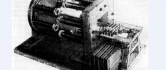
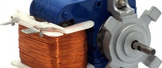
In household appliances, hand-held power tools, automotive electrical equipment and automation systems, a commutator AC motor is often used, the connection diagram of which, as well as the device, are similar to DC motors.
Their widespread use is explained by their compactness, low weight, low cost and ease of operation. In this segment, motors with high frequency and low power are most in demand.
Operating principle and design features
This device is quite specific, having, due to its similarity with DC machines, similar characteristics and inherent advantages.
The difference from DC motors is the material of the stator housing, made of sheets of electrical steel, due to which it is possible to reduce eddy current losses.
So that the engine can operate from a regular network, i.e. 220 V, field windings are connected in series.
These motors, called universal due to the fact that they operate on alternating and direct current, are single- and three-phase.
Video: Universal brushed motor
What does the structure consist of?
The design of an AC electric motor includes, in addition to the rotor and stator:
- tachogenerator;
- brush-collector mechanism.
The armature current interacts with the magnetic flux of the field winding, causing rotor rotation in the collector mechanism. Current is supplied through the brushes to the commutator, which is the rotor assembly and is connected in series to the stator winding. It is assembled from plates with a trapezoidal cross-section.
The principle of operation of such an engine can be demonstrated using the well-known experiment from school with a rotating frame, which was placed between opposite poles of a magnetic field. It rotates under the influence of dynamic forces when current flows through it. When changing the direction of the current, the frame does not change the direction of rotation.
High idle speeds caused by the maximum torque when connecting the field windings in series can lead to failure of the mechanism.
Checking the commutator motor for malfunction
The most difficult task that will confront you is analysis. It turns out that the commutator motor is difficult to disassemble. It would be unnecessary to provide an analysis of engine dismantling for all types of devices in one article, so it is better to find special instructions directly for your device. Moreover, this will eliminate the possibility of additional breakdowns when working with specific designs from different manufacturers. Do not forget about safety precautions; any device must be disconnected from the power source when disassembling. Use tools with insulating material. Within the framework of the article, we will consider the case when the device is completely faulty, works intermittently or incorrectly.
With the motor removed, try applying voltage to it. If the engine is running, but there is increased sparking on the brush contacts (the tails of the sparks are distributed unevenly during rotation, sometimes covering more than 90°), most likely it’s time to replace them or adjust the fastening of the mechanism - if the contact is poor, problems may occur. In extreme cases, this could even mean an interturn short circuit inside the motor. It is necessary to replace brushes only with the same type. Brushes are most often secured using a clamp or bolts. Sometimes they are mounted on a special holder. If the brushes are in order, but poorly secured, the pressure springs need to be adjusted.
If the contacts on the collectors are blackened, it is necessary to clean them. Fine sandpaper is best for this. If this does not help, then in half of the cases the cause of the malfunction is wear of the bearings. If you notice noise or additional vibration during operation, then these are sure signs that the bearings need to be replaced. If the device does not start at all, visually check the integrity of the windings and the absence of blackening.
Burnt insulation must be cleaned, and if there is graphite dust, everything must be thoroughly cleaned. Dust can cause short circuits. All electrical wiring must be tested with a multimeter. If the winding does not show conductivity, then, unfortunately, repairing the engine in most cases will cost more than a new one. This is how this electric motor is repaired and tested.
Connection diagram (simplified)
A typical connection diagram provides for the output of up to ten contacts to the contact strip. The current L flowing through one of the brushes enters the commutator and armature, then passes to the stator windings through the second brush and jumper, leaving the neutral N.
This method of connection does not provide for reversing the motor, since connecting the windings in parallel leads to a simultaneous change in the poles of the magnetic fields. As a result, the direction of the moment is always the same.
We recommend:
It is possible to change the direction of rotation if you change the locations of the winding outputs on the contact strip. The motor is turned on directly when the rotor and stator outputs are connected to a brush-commutator mechanism. To turn on the second speed, the terminals of half the winding are used. We must not forget that from the moment of such connection the motor operates at maximum power, so its operation time cannot exceed 15 seconds.
Video: Connecting and adjusting engine speed from a washing machine
Engine control
In practice, various methods of regulating engine operation are used. This can be an electronic circuit where the regulating element is a triac, which “passes” a given voltage to the motor. It works like an instantaneous key, opening when a control impulse is received at its gate.
The principle of operation implemented in circuits with a triac is based on full-wave phase control, where the voltage supplied to the motor is tied to the pulses that arrive at the electrode. In this case, the frequency with which the armature rotates is directly proportional to the voltage supplied to the windings.
Simplified, this principle can be described by the following points:
- a signal from an electronic circuit is supplied to the triac gate;
- the gate opens, current flows through the stator windings, causing the motor armature M to rotate;
- instantaneous rotation speed values are converted by the tachogenerator into electrical signals, forming feedback with control pulses;
- as a result, the rotation of the rotor remains uniform under any load;
- Using relays R and R1, the motor is reversed.
Another circuit is a phase-pulse thyristoran.
Machine advantages and disadvantages
The advantages include:
- small sizes;
- versatility, i.e. work on constant and alternating voltage;
- high starting torque;
- independence from network frequency;
- speed;
- soft adjustment of rotation speed over a wide range when varying the supply voltage.
Disadvantages are also associated with the use of a brush-collector junction, which entails:
- reducing the service life of the mechanism;
- sparks occurring between the brushes and the commutator;
- high noise level;
- a large number of collector elements.
Basic faults
The sparking that occurs between the brushes and the commutator is the most important issue that requires attention. To avoid more serious malfunctions, such as peeling and deformation of the lamellas or overheating of the lamellas, a worn-out brush must be replaced.
In addition, a short circuit between the armature and stator windings is possible, causing strong sparking at the commutator-brush junction or a significant drop in the magnetic field.
To extend the service life of the engine, two conditions must be met - a professional manufacturer and a competent user, i.e. strict adherence to operating hours.
Video: Brushed electric motor
We are returning again to the world of entertaining things - like electrical engineering , because I think that we all simply need this knowledge in our daily lives.
Read also: Knife from a circular saw blade
Connecting a single-phase commutator motor - AC
In this topic, you need to understand exactly how a single-phase AC commutator motor is connected, for example, after it has been repaired. The electrical circuit in Fig. 1 gives us an idea of the nature of the electrical connections, that is, here we can notice that the two stator windings of the electric motor in the electrical circuit are in series connection, and the two rotor windings of the electric motor relative to the external voltage source are connected in parallel and the electrical circuit for this example, it is closed on the rotor windings of the electric motor.
Who among us analyzed household electricity consumers as:
and further, they will agree with me that for the electrical circuit in Fig. 1 one more element is missing - a capacitor. Therefore, to this name of the motor type you can also add the name capacitor electric motor. If you follow logical thinking, then the capacitor in the electric motor circuit is necessarily connected to the starting winding of the stator, which serves to initially shift the rotor. Accordingly, we came to the conclusion that the capacitor must be directly in series connection with the starting winding. For example, a diagram of a single-phase motor with working and starting stator windings is shown, where the resistance on each winding will take its own value (Fig. 2).
Depending on the types of asynchronous motors and their application (Fig. 3), there are the following connection diagrams to a single-phase network:
a) ohmic phase shift, bifilar method of winding the starting winding;
b) capacitive phase shift with a starting capacitor;
c) capacitive phase shift with a starting and running capacitor;
d) capacitive phase shift with a working capacitor.
The diagrams indicate the following designations:
Before connecting a commutator single-phase motor , it is necessary to determine:
stator windings. The capacitor, with its capacitance and voltage ratings, and the corresponding data for a particular type of motor, should be connected to the stator starting winding - in series. The resistance of the stator windings takes the following average values:
- working winding 10-13 Ohm;
- starting winding 30-35 Ohm;
- total winding resistance 40-45 Ohm,
- for some types of household appliances. By measuring the resistance at the wire terminals of the stator windings, you can determine the starting winding with its average value. That is, the resistance of the starting winding takes the average value between the working winding and the total resistance of the two windings - working and starting.
Variable network: motor 380 to network 380
To reversibly connect a three-phase asynchronous electric motor, we will take as a basis the circuit diagram for connecting it without reversing:
This scheme allows the shaft to rotate only in one direction - forward. To make it turn into another, you need to swap places of any two phases. But in electrics it is customary to change only A and B, despite the fact that changing A to C and B to C would lead to the same result. Schematically it will look like this:
To connect you will additionally need:
- Magnetic starter (or contactor) – KM2;
- Three-button station, consisting of two normally closed and one normally open contacts (a Start2 button has been added).
Important! In electrical engineering, a normally closed contact is a state of a push-button contact that has only two unbalanced states. The first position (normal) is working (closed), and the second is passive (open). The concept of a normally open contact is formulated in the same way. In the first position the button is passive, and in the second it is active. It is clear that such a button will be called “STOP”, while the other two are “FORWARD” and “BACK”.
The reverse connection scheme differs little from the simple one. Its main difference is the electric locking. It is necessary to prevent the motor from starting in two directions at once, which would lead to breakdown. Structurally, the interlock is a block with magnetic starter terminals that are connected in the control circuit.
Control of a commutator motor - without a rheostat
To control a commutator motor - without a rheostat, a packet switch is quite suitable, with the help of which the contact group is switched - in the switch Fig. 4.
In this example, depending on the switching position, the direction of rotation of the electric motor rotor will change, operation is carried out at a constant speed and engine speed, only the polarity of the stator windings changes.
cam packet switch
To control the rotation speed of the electric motor rotor, you can use a triac rotation speed controller. This electrical installation product, like all others, is selected taking into account the rated current and voltage values - the connected load and the power of the electrical energy consumer are taken into account.
The consumer power, as is clearly seen from the formula in Fig. 5, is the product of current and voltage. Why is it necessary to carry out preliminary calculations at all? The load, as we know, is connected through a residual current circuit breaker. To install and connect a residual current circuit breaker, take into account the calculation of the load current strength in Fig. 6.
triac motor speed controller
In short, to imagine what a triac regulator is, you again need to remember the basics of electronics. The triac, which is part of the control circuit, performs the function of a regulating element - to power the electric motor (Fig. 7).
The figure shows the conclusions of the triac:
When a pulse arrives at input G, the triac opens (Fig. 8), that is, it acts as an electronic key to power the electric motor.
The photograph shows an image of the electronic control module. An electronic control module is found in automatic washing machines operating in a preset, automatic mode.
Indesit washing machine electronic control module
Connecting a commutator motor - via a rheostat
This schematic diagram, Fig. 9, shows the connection of the load to the output terminals of the generator through a rheostat. The load here is an electric incandescent lamp. The rheostat in the electrical circuit is connected in series, the load light bulb is connected in parallel in the circuit. In the same way, instead of this load, you can connect a commutator motor powered by electrical energy sources, such as:
or from an external energy source, that is, from the electrical network. When connecting a commutator motor, you need to take into account the electrical diagram of the stator windings and the type of motor, as is permissible for the following diagram in Fig. 10.
The electrical circuit is a circuit of a universal commutator motor, where the motor can operate on both alternating and direct current.
At one time, I made a certain number of electric emery machines, electric motors were mounted on a platform and then connected, an attachment for installing an emery wheel was attached to the rotor shaft, therefore, in my practice I had to connect various types of electric motors.
Read also: Optimal height of a workbench in a garage
The given example of electric emery sanders is a rather interesting and useful topic for our everyday needs.
It remains to wish you successful repairs for various types of household appliances.
The article was not written by a technically literate moron, a diagram of a brushless motor, but a description of a brushed motor and vice versa.
Hello electrician. What circuits do you mean with the names: “brushless and brushed motors”? The diagrams provide an explanation of the connection of the windings of the commutator motor. You do not need to introduce yourself as an electrician, but indicate your name. For example, I have a first name, patronymic and last name - Viktor Georgievich Povaga. I live in Siberia, I work under an agreement with Yandex.Direct. Next time, if you receive such a letter, I will contact the Internet company to search for you and then, before the court, you will prove “who I am.” All the best to you, “electrician.”
Victor Georgievich! Thank you very much for the useful article.
Hello. I don’t understand anything about electrics, but I need to connect the IP-22 DC electric motor to a regular network
Hello. In my practice, I have not seen this type of IP-22 electric motor. I don’t understand what you are talking about here - the IP-22 fire detector or the electric motor? Indicate the technical specifications for your electric motor and country of origin so that I can navigate your question.
Good afternoon, Victor! Tell me, will a triac converter regulate the rotation speed of the UL-062-UHL4 commutator motor without reducing the torque on the shaft? Frequency converters cope with this issue, but their use to control this engine model is not permissible.
Greetings Valentin. The rotation speed of the universal commutator motor can be controlled by a triac power regulator. A triac converter can be understood as a triac voltage stabilizer.
I'm afraid to offend the author, but in my opinion, there really is confusion with the names of engine types. Commutator and single-phase asynchronous are two different types of motors. If a capacitor is present in a commutator motor, it is, in principle, an optional element. Most often, sometimes in combination with chokes, to protect the network from interference generated by the engine (filter). The engine itself will work without a capacitor, one can only argue about the spark extinguishing effect. Therefore, calling a commutator motor a capacitor motor is misleading. In an asynchronous single-phase motor, the capacitor serves to shift the PHASE in the starting winding. Without it - a phase shift, the rotor will not really start to rotate. After spinning up to speeds close to the nominal speed, the engine will operate without a starting winding, but with significantly less torque. Phase shift can be achieved in other ways - using inductance or a resistive load. Then it will not be an asynchronous motor with CAPACITOR starting (in this particular case).
I'm afraid to offend the author, but there really is confusion with the names of electric motors. In a commutator motor, the capacitor is not a necessary element. The power supply circuit of a commutator motor may contain a capacitor, often in combination with inductors, but this is to protect the network from interference generated by the motor commutator (filter). It is not required for engine operation. One can only argue about the need for it to extinguish sparks. Therefore, calling a commutator motor a capacitor motor is not correct. In an asynchronous “single-phase” motor, a capacitor in the starting winding circuit serves to shift the phase in it. And this is also only an option, although the most common one. The phase shift can be achieved by including an inductance or active resistance in the starting winding circuit. So it is more appropriate to talk about capacitor starting of an asynchronous electric motor in a single-phase network. In this case, it would be more correct to call the motor two-phase. One phase is from the network, the second is artificially shifted. After starting, when the engine reaches speed close to the nominal one, the starting winding can be turned off, the engine will work, but its torque will be significantly less.
Hello. Here, in general, I hastened to express my opinion, calling the commutator motor a capacitor motor. It was nice talking with you. Happy belated holidays to you.
Tell me how to connect the UL-062 engine to the 220 network
Hello. I did not find a diagram for this electric motor. If you believe the information that I was able to find on the Internet, then connecting the motor (UL-062) looks like this: an alternating voltage of 220 Volts is connected to the contact terminals (on the terminal block) O1Y2 and S1Sh2, a jumper is installed on the other two contact terminals (a segment wires). Before connecting, I recommend checking the operation of the electric motor at low voltage.
There are 6 terminals on the terminal block, sometimes there are 8. What to connect where
Single-phase 220V electric motors are widely used in a variety of household and industrial devices: refrigerators, washing machines, pumps, drills, sharpening and similar processing machines. Their technical characteristics are somewhat inferior to those of three-phase motors. There are two most common types of single-phase electric motors for power frequency AC power:
Read also: How to cut car glass
The former are simpler in design, but have a number of disadvantages, the main of which are difficulties in changing the direction and speed of rotation of the rotor.
Next, single-phase asynchronous electric motors and commutator AC motors are considered.
Types of CD
It is customary to classify these devices according to the type of power supply; depending on this, two groups of CDs are distinguished:
- Direct current. Such machines are characterized by high starting torque, smooth speed control and a relatively simple design.
- Universal. They can operate from both constant and variable power sources. They are distinguished by their compact size, low cost and ease of management.
The first ones are divided into two subtypes; depending on the organization of the inductor, it can be on permanent magnets or special excitation coils. They serve to create the magnetic flux necessary to generate torque. CDs, where excitation coils are used, are distinguished by types of windings, they can be:
- independent;
- parallel;
- consistent;
- mixed.
Having dealt with the types, let's consider each of them.
Universal type CD
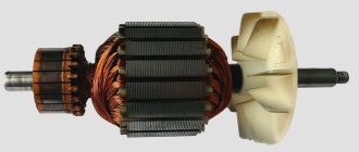
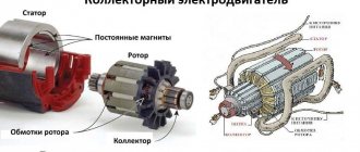
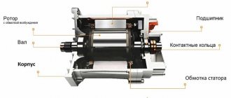
The figure below shows the appearance of an electric machine of this type and its main structural elements. This design is typical for almost all CDs.
Design of a universal commutator motor
Designations:
- A is a mechanical commutator, it is also called a collector, its functions were described above.
- B – brush holders, used to attach brushes (usually made of graphite), through which voltage is supplied to the armature windings.
- C – Stator core (made up of plates, the material for which is electrical steel).
- D – Stator windings, this unit belongs to the excitation system (inductor).
- E – Armature shaft.
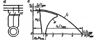
For devices of this type, excitation can be serial or parallel, but since the latter option is not currently produced, we will not consider it. As for universal sequential excitation CDs, a typical diagram of such electric machines is presented below.
Scheme of a universal commutator motor
A universal CD can operate on alternating voltage due to the fact that when the polarity changes, the current in the field and armature windings also changes direction. As a result of this, the torque does not change its direction.
Features and scope of universal CDs
The main disadvantages of this device appear when it is connected to AC voltage sources, which is reflected in the following:
- decrease in efficiency;
- increased sparking in the brush-collector unit, and as a result, its rapid wear.
Previously, CDs were widely used in many household electrical appliances (tools, washing machines, vacuum cleaners, etc.). At the moment, manufacturers have practically stopped using this type of motor, giving preference to brushless electric machines.
Now let's look at collector electric machines operating from constant voltage sources.
CD with permanent magnet inductor
Structurally, such electric machines differ from universal ones in that permanent magnets are used instead of excitation coils.
Design of a permanent magnet commutator motor and its diagram
This type of CD is most widespread compared to other electric machines of this type. This is due to the low cost due to the simplicity of the design, simple control of the rotation speed (depending on voltage) and changing its direction (it is enough to change the polarity). The motor power directly depends on the field strength created by the permanent magnets, which introduces certain restrictions.
The main area of application is low-power drives for various equipment, often used in children's toys.
CD on permanent magnets from a toy from the times of the USSR
The advantages include the following qualities:
- high torque even at low speed;
- dynamic management;
- low cost.
Main disadvantages:
- low power;
- magnets lose their properties due to overheating or over time.
To eliminate one of the main disadvantages of these devices (magnet aging), special windings are used in the excitation system; let’s move on to considering such CDs.
Independent and parallel field coils
The first received this name due to the fact that the windings of the inductor and armature are not connected to each other and are powered separately (see A in Fig. 6).
Figure 6. CD circuits with independent (A) and parallel (B) excitation windings
The peculiarity of this connection is that the power supply U and UK must be different, otherwise a moment of force will arise. If it is impossible to organize such conditions, then the armature and inductor coils are connected in parallel (see B in Fig. 6). Both types of CD have the same characteristics; we found it possible to combine them in one section.
Single-phase asynchronous electric motors
Device and principle of operation
The power of such a single-phase 220V motor can, depending on the design, range from 5 W to 10 kW. Its rotor is usually a short-circuited winding (“squirrel cage”) - copper or aluminum rods closed at the ends.
Such a single-phase motor usually has two windings offset by 90° relative to each other. The working (main) one occupies most of the stator slots, and the starting (auxiliary) one occupies the remaining part. And it is called single-phase because it has only one working winding.
Alternating current flowing through the main winding creates a periodically changing magnetic field. It can be considered to consist of two circular ones with the same amplitude, rotating towards each other.
According to the law of electromagnetic induction, in closed turns of the rotor, a changing magnetic flux creates an induced current that interacts with the field that generates it. If the rotor is stationary, the moments of the forces acting on it are the same, as a result of which the rotor remains stationary.
If the rotor begins to rotate, then the equality of the moments of these forces will be violated, since the sliding of its turns relative to the rotating magnetic fields will become different. As a consequence, the Ampere force acting on the rotor turns from the direct magnetic field will be significantly greater than from the reverse one.
An induced current in the rotor turns can only arise when they cross the magnetic field lines. And to do this, they must rotate at a speed slightly lower than the field rotation frequency (with one pair of poles - 3000 rpm). Hence the name that such electric motors received, asynchronous.
As the mechanical load increases, the rotation speed decreases and the magnitude of the induction current in the rotor turns increases. As a result, both the mechanical power of the engine and the power of the alternating current it consumes increase.
Startup and connection diagram
It is clear that it is inconvenient to manually spin the rotor every time you start the electric motor. The starting winding is used to create the initial starting torque. Since it makes a right angle with the working winding, in order to create a rotating magnetic field, the current in it must be shifted in phase relative to the current in the working winding by also 90°.
This can be achieved by including a phase-shifting element in its power supply circuit. A resistor or inductor cannot provide a phase shift of 90°, so in most situations it is logical to use a capacitor as a phase-shifting element. In this case, a single-phase electric motor has the best starting properties.
When the phase-shifting element is a capacitor, single-phase electric motors can be structurally as follows:
- with a starting capacitor (Fig. a);
- with starting and working (Fig. b);
- only with a working capacitor (Fig. c).
The first (most common) option involves connecting the starting winding with a capacitor for a short time during the start-up, after which they are turned off. It can be implemented using a time relay, or even simply by closing the circuit while pressing the start button. This starting circuit is characterized by a relatively small starting current, but in rated mode the characteristics are low. The reason is that the stator field is elliptical (it is stronger in the pole direction than in the perpendicular direction).
A circuit with a working, always-on capacitor works better in nominal mode, but has mediocre starting characteristics. The option with a starting and running capacitor is intermediate between the two described above. Calculating the values of their capacitances is relatively simple: for the working one 0.75 μF per 1 kW of power, for the starting one - 2.5 times more.
Reversing three-phase asynchronous machines
The direction of movement of the rotating magnetic field of asynchronous electric motors depends on the order of the phases, regardless of whether its stator windings are connected by a star or a triangle. For example, if phases A, B, C are applied to input terminals 1, 2 and 3, respectively, then the rotation will go (supposedly) clockwise, and if to terminals 2, 1, and 3, then counterclockwise. The connection diagram via a magnetic starter will save you from the need to unscrew the nuts in the terminal box and physically rearrange the wires.
Three-phase asynchronous machines at 380 volts are usually connected with a magnetic starter, in which three contacts are located on the same frame and close simultaneously, subject to the action of the so-called retractor coil - a magnetic solenoid operating on both 380 and 220 volts. This saves the operator from close contact with live parts, which can be unsafe at currents above 20 amperes.
For reverse starting, a pair of starters is used. The supply voltage terminals at the input are connected in a direct manner: 1–1, 2–2, 3–3. And at the exit counter: 4–5, 5–4, 6–6. To avoid a short circuit when accidentally pressing two “Start” buttons on the control panel simultaneously, voltage is supplied to the retractor coils through additional contacts of opposite starters. So that when the main group of contacts is closed, the line that goes to the solenoid of the adjacent device is open.
The control panel is equipped with a three-button post with single-position – one action per press – buttons: one “Stop” and two “Start”. The wiring in it is as follows:
- one phase wire is fed to the “Stop” button (it is always normally closed) and jumpers from it to the “Start” buttons, which are always normally open.
- From the “Stop” button there are two wires to additional contacts of the starters, which close when they are triggered. This ensures blocking.
- From the “Start” buttons, cross one wire to the additional contacts of the starters, which open when they are triggered.
Read more about connection diagrams for magnetic starters for three-phase electric motors here.
AC brushed motor
Consider a brushed AC motor. Universal commutator motors can be powered from both AC and DC sources. They are often used in power tools, sewing and washing machines, meat grinders - where reverse is needed, adjustment of the rotor speed or its rotation at a frequency of more than 3000 rpm.
The stator and rotor windings of a commutator motor are connected in series. Current is supplied to the rotor windings through brushes in contact with the commutator plates, to which the ends of the rotor windings are connected.
Reversing a single-phase motor with a commutator is carried out by changing the polarity of the stator or rotor windings being connected to the network, and the rotation speed can be adjusted by changing the amount of current in the windings.
The main disadvantages of such an engine:
- high price;
- the complexity of the device, the practical impossibility of repairing it independently;
- significant noise level, difficult to control, creating radio interference.
It remains to add that when using devices containing a single-phase electric motor, close attention should be paid to the choice of its type, connection diagram, and how to correctly calculate the elements.
Pages
Reverse commutator motor
When using a switch like the one in the photo
There is a more visual diagram for connecting the reverse, maybe it will help someone.