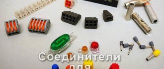
Old-fashioned methods of connecting electrical wires are becoming obsolete. Twists, electrical tape, pliers - all this is no longer used in modern construction. They were replaced by terminal blocks for connecting wires. What is it, what are the varieties of this element, how are they used in electrical networks - we will understand.
Terminal blocks for connecting electrical wires Source i8.photo.2gis.com
How and what to connect the wires with
In addition to terminal blocks, electricians use different methods for connecting electrical cable cores. Here they are:
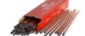
- soldering - used when there is confidence that the connection area will not heat up;
- welding is an excellent option, but requires the use of special equipment;
- crimping , where special sleeves are used;
- bolted connection - usually used if it is necessary to connect wires made of different metals.
That is, it turns out that when choosing a docking method, it is necessary to take into account several factors. Namely:
- cable core thickness;
- the metal from which they are made;
- operating conditions of the joint;
- number of connected cores;
- type of insulating material used in cable products.
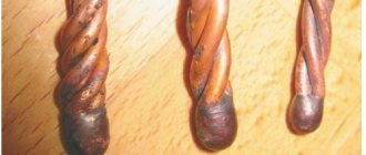
Of course, not all electricians have given up twisting. Especially when connecting wires of small cross-section. It’s easier and faster to twist them with your fingers and wrap them with electrical tape. Although all regulatory documents have already excluded insulating tape from the list of materials that can create safe operating conditions for electrical networks. It is recommended to use heat shrink tubing instead.
Heat shrink tube for insulating wire connections Source setgroup.ru
It is simply pressed onto the joint and heated, for example, with a lighter. The tube heats up, partially melts and compresses the joint, insulating it. It's not as fast as using electrical tape, but it's several times more reliable.
All of the above methods for connecting wires are complex and require either specialized equipment or some kind of tool. In this regard, the terminal blocks are simpler, more reliable, and cheaper. Therefore, we will further disassemble only the terminal clamps.
CS-CS.Net: Laboratory of the Electroshaman
Terminals for convenient connection of outgoing lines in the switchboard
Hi all! It so happened that several times by mail various people bombarded me with two questions: why the hell do I install terminals in switchboards if cables can be connected directly to the automatic devices there and how to correctly connect zero to the .NLP terminals if you use jumpers.
Attention! In August 2022, ABB transferred the EntrElec plant, which produces terminals, clamps and cross-connections, to TE Connectivity. Everything is in order: all terminal articles and all terminals remain, they will simply be called instead of “ ABB D4/6.NLP” - “TE (EntrElec) D4/6.NLP”. All order codes are saved. Read about it (and stay tuned) in my post with all the information .
TE also made a navigator in Excel for their terminals with the ability to select by parameters. I uploaded the file to my hosting here: TE-Entrelec-Connectors-Selection.xlsx (~1.3 MB) .
In principle, the questions are simple and easy, but it so happened that by mail to one guy I found as many as five ideas for why terminals are needed in the panel and I thought - why is this answer disappearing: Well, I decided to write a post. There won’t be any recent photos here, I’ll pull them from other posts, because here we need them only to illustrate some points.
And yet I will not go into detail about some points. You remember that I make everyone think by giving them the right ideas, and I don’t post ready-made solutions for repetitions?
What to read (all links to terminals)
Yes Yes. I’ll collect all the links in a pile so that you can refer to them later and those who find this post have everything at hand:
- About ordinary terminals for large cross-sections;
- About multi-level terminals .NLP and .DA;
- About jumpers for these terminals;
- About terminal clamps on DIN rail (BAM4).
If you try to explain briefly, DIN rail terminals consist of things like these:
- The terminals themselves . For large sections they are produced separately (there are terminals for 70 and even 240 squares O_o), and in some cases they are produced in the form of one terminal, but with several contacts (L, N, PE or just three contacts for any purpose).
- The terminals are designed to be mounted on a DIN rail, because they take PE from it (they do not have contacts for inserting PE into the terminal). Terminals of small cross-sections are snapped onto the rail, and terminals of large cross-sections are tightened onto it with a screw in order to have good contact and hold the ground fault current.
- Typically, one side of the terminals is closed and the other is open. This is done so that the terminals are as narrow as possible in width and do not take up much space. The terminal insulation is designed and designed for this type of application.
- In order to cover the edge of the terminal assembly (the last terminal that will be open side out), end insulators . These insulators can also be used to separate different logical groups of terminals from each other.
- Jumpers are available for the terminals . These are special plates that connect adjacent terminals to each other. The jumpers for each type of terminal will be different, because terminals of different types and cross-sections have their own width and the width of the jumper should also be the same as that of the terminal. Jumpers can only be placed on those terminals that are located close to each other without end insulators. Also, jumpers are usually designed for the same current that one terminal is designed for (we’ll talk about this later).
- It is convenient to fix the terminal assemblies with special clamps. They usually have a large height in order to press the terminal not from below at the rail, but along the entire height. For ABB these are BAM4 clamps. They also have special PEAD inserts into which you can insert a piece of paper with the signature of a number of terminals.
Where is it convenient to use terminals in switchboards and how can they be useful?
My path with terminals was thorny and long. At first I didn’t know why I should use them, and then gradually I began to make small inserts on them for automation in shields. For example, if we have some kind of control cable, then instead of explaining to the customer: “... the first wire must be slipped along with the phase from the Q12 machine, the second - to contact A1 of the K15 relay, and the third - to this zero bus” we can just put the terminals for this cable, number them, and connect everything in the panel with a flexible wire. And let the customer connect to the terminals.
Gradually this idea grew and became stronger, and when I made my first huge rack panel, I made all the automation lines there on the terminals. This is what it looked like:
Terminal blocks for connecting lighting automation
But my power lines went there without terminals. For them I intended to use N/PE tires. Here they are visible from the bottom of the photo:
View of the assembled part of the control panel automation (pulse relays)
As a result, the shield connection looked like this:
Connecting the power part: terminal blocks would also be useful
The question is... if such huge boards were available (by those standards), then why not try to order special terminals for the board, which were listed in the catalog as “... for electrical panels”? These were D4/6.NLP terminals, to which the entire cable with a cross-section of up to 3x2.5 can be conveniently connected.
And this is what my first shield looked like on them on these terminals:
Almost all connections are complete!
There were more cables because I brought all the lines here (including the power ones), and the terminals took up less space. And after that I took a leap! I learned from experience that terminals simplify working with switchboards if the switchboards are large or have complex automation. And then the first customer approached me, who asked me to make a shield with terminals so that stupid workers would not touch anything in the shield except these terminals. And - it started spinning!
So, let's get some ideas on where terminals might fit.
Firstly , the terminals are convenient to install if you need to connect thick armored cables or a short input cable to the shield. Instead of dragging a cable, for example, 4x16, to the input switch of the switchboard (which is located at the top), you can put the terminals at the bottom of the switchboard, and then run everything with soft wires. This is how it was done in the shield in Povarovo:
Input terminals for network, generator, stabilizers. Also signed
And this is how it was done in the shield in CITY for 4x70 and 5x25 cables:
Terminals for connecting power cables 70 sq. mm.
Secondly , if the shield itself is large (cabinet type B/TwinLine), then it is convenient to install the terminals in order to... save CABLE! Because we usually place the terminals on the side of the cabinet from which the cables enter it. In this case, we will need a small supply of cables - only up to the terminals (for example, 0.5 meters). And if you run cables directly to the machines, then you will need at least one and a half cabinet heights (for example, 2 meters).
Let's do the math? Let's say 90 cables come to us. If we do everything at the terminals, then our margin difference will be 2-0.5 = 1.5 meters for each cable! 90 x 1.5 = 135 meters! Yes, this is a whole bay of cable, damn it! But the terminals also provide a very convenient connection, if you also take care of the free space around them:
All outgoing lines of the shield are made on terminals for convenience
Thirdly , we have already talked about automation. As soon as lines are installed in the panel for some taps, buttons, light bulbs, then you cannot do without terminals.
Fourthly , sometimes terminals are needed due to the design of the shield itself. For example, when they order shields from me on a bare WR frame, there will be no place through which the wires from the cables can be dragged to the machines - they can only be pushed behind the DIN rails.
That's why I always install terminals in such shields. Here is a beautiful photo of how Kirich connected my shield to the WR frame:
For fun, the wires are folded into loops and aligned with a laser level.
Fifthly , terminals should be used when we need to combine several cables into one. Some people like to do wiring without junction boxes, but not by installing them in socket boxes, but by bringing the cables from each block of sockets into a shield. Then it may turn out that there are five cables coming from some room, which should end up on one machine.
This is where jumper terminals come to the rescue. This is what it looks like in the Militia shield:
Terminals for connecting outgoing lines
Do you see how the wires don't fit into some terminals? That's where the jumpers are! And since we started doing something on the terminals, it makes sense to combine all the terminal technologies in one pile and make the entire board on the terminals, like this:
Space inside the housing for cables near the terminals
There is also some free space left for cutting cables (as it should be).
And sixthly , yes - stupid workers. Sometimes customers directly ask me: “My workers are stupid! Can I do everything on the terminals so that they don’t fit anywhere other than the terminals?”
Terminals must be used wisely. What are the problems with them?
I would highlight two jambs that need to be taken into account if you want to make a shield on the terminals.
The first jamb - do not forget to count the width of the terminals and check whether they will fit on the DIN rail . And don’t forget to take into account the width of the BAM4 clamp if you need to separate the terminal assemblies among themselves for beauty.
CS CRM: DIN Rail Terminal Width Calculator
For myself, I screwed up 1Sku so that it could count the width of the terminals I needed with a margin and made the following unspoken rule: if the terminals barely fit on the rail in 1Ska, then in real life they are guaranteed to fit into the shield.
And the second jamb is not really a jamb, but a feature. Still, sooner or later you will understand that you need to leave room for cables near the terminals . Here is an example of a bad shield on StaroVolynskaya:
Poorly done: terminals too close to the edge of the shield
Here the customer insisted that we use shields of the simple AT/U series, and they turned out to be jam-packed. As a result, there was almost no space left for the terminals (and there was automation - the terminals were needed), and the distance from the edge of the terminals to the panel body was only about 2-3 centimeters.
This is what it looks like:
Distance from terminals to edge of housing
The fun of using terminals is to leave some free space around them. Then in this place you can make any (and ugly) mess for cables! That is, then the shield is divided into two parts: a clean and neat shield, and a place for cables, where you can do what you want and how you want.
This is how it should be:
Space for cables inside the switchboard
I have adopted the following rule for myself: if the terminals occupy one DIN rail, then we leave another DIN rail as free space. That is, we take a module for double-height terminals and simply do not install one rail. Well, if the terminals will occupy two rails, then (if the cabinet allows it) we take a triple-height module.
That's probably all about the features of terminal installation.
A chip with zeros from RCDs on the .NLP terminals.
And now I will again try to explain the trick, which I already explained in the post about jumpers for terminals. The point is that when we find out that there are jumpers for the terminals, a great thought comes to our mind: “Wow! Then since I have ten machines under the RCD, I’ll put a jumper on the terminals and throw a zero with one wire!
Then they usually think like this:
- This is... so... ten machine guns. Each is 16A. What kind of zero cross section should this be? Well.. no less than the input cable. For ten squares. - Oh... how can I stuff ten squares into a terminal with 2.5...4 squares? Why won't it fit?
And then they usually write to me or anywhere on the blog or on soap =) That's right! If “it” doesn’t fit, then it’s intended to make you think. And the first question you need to ask yourself is: “Why did you even decide that this jumper should withstand the hellish total current of zeros?”
That's right! She shouldn't be holding him! Typically, a jumper is rated for the same current as one terminal. And therefore, jumpers can be used when their current is limited by something external (automatic) and there will not be more than the current of one terminal (for .NLP this is about 32-38A; we take the worst option at 32A).
Let's describe different cases:
- If the terminals are used to multiply the line from one machine to several, then all these several terminals will be under one 10..16A machine - so the jumper can be used without problems (and is necessary).
- If the terminals are used to control lights or something else. For example, the phase from the machine went through three pulse relays to three terminals. Then through these three terminals the total load will never be greater than the rating of the machine. And that means the jumper can be used.
- If the total sum of the values of the machines that are output to the terminals and whose zeros you want to connect is greater than the value of the jumper, then that’s it, the jumper cannot be used just like that. But it is in this case that you will need a large cross-section wire, you will not stuff it in and think about it =)
I solve the last option cunningly. I COUNT how many machines I have under the common zero and I still put a jumper on the zeros, but I stretch this zero with several separate wires. Here are examples of such calculations:
- RCD for 40A, there are 4 machines of 10A each (light). So it will be 40A in total. We put a jumper and drag the zeros with three wires of 2.5 squares each. One of the terminals is powered by the adjacent jumper.
- 40A RCD, 4 16A circuit breakers (sockets). The current is still limited to 40A (since the ouzo is selected at 40 by the input machine). But to be on the safe side, in this case I will drag in four zeros. A jumper is placed here in order to equalize the currents in parallel wires.
But if under one RCD there are a bunch of machines (for example, 10) of 16A each, then there may be a whole bunch of options. We believe that we have a 63A RCD for single-phase switchboards:
- I would have installed a BRU/DBL block (or another) and still managed to get all 10 zeros through separate wires. Power lines - no use saving!
- You can switch to wires of 4 squares and push them into the terminals one at a time, because anyway the RCD is selected for 63A and the total cross-section can be no more than 10 squares inside the shield.
- You can split these lines into several RCDs (this will be the best option of all)
How to cram several wires into one RCD terminal? I liked using NShVI(2) tips. It turned out that such tips fit a certain number of 2.5 square wires. For example, in NSHVI(2) 5-6 wires of 2.5 each can be crammed into 10 squares. In NSHVI(2) for 6 square meters there are 4 wires of 2.5 each.
This is what it looks like in the shields. A pack of zero wires comes out of the RCD:
Installation of the panel inside: from RCDs and automatic circuit breakers - to terminals
And then it comes to the terminals in a row:
Terminals D4/6.NLP for connecting outgoing lines (top)
When I assemble a shield, I estimate the approximate length of one wire, cut a bundle of them and crimp them into one NShVI. And then I cut them locally to the required length at each terminal and screw them in there. That's all the secrets!
Classification of terminal blocks
It should be noted right away that this connecting element is used today in all types of electrical installation work. Therefore, manufacturers offer a fairly wide range of them. For example, you can buy small connectors on the market that are designed to connect one pair or a system of pairs at the same time.
According to the installation method, terminal blocks are divided into:
- connectors for individual wires;
- for boards used in electronics;
- so-called DIN rails;
- installed near cross-modules.
Let us add that these elements are also divided by the number of rows in one connecting block and by how the wire is clamped. Here it is either a straight clamp or an angular one.
Terminal block mounted on a DIN rail Source www.elektrikaup.ee
Now the classification according to the structural device:
- Screw. Everything is simple here - the screw is the main clamping element that compresses the wire between two metal washers.
- Detachable . The design of these elements contains a spring. She clamps the inserted wire when the lever presses her. When lowered, the latter compresses the cable core and releases it when raised. A convenient option because the installation process itself is very simple.
- Terminal blocks for expansion boxes. They are directly mounted into the junction box. The method of fastening the wires is either screw or spring.
- With safety lock. Here, a fuse is inserted into the design of the device, which protects the network from overvoltage. It should be noted that these devices have large overall dimensions compared to other types.
- Terminal blocks for connecting wires. A convenient option because they can be used to connect several wires from different materials with different cross-sections. In this case, the cores of different wires do not contact each other. The only thing you need to pay attention to is the rated current that these terminal blocks can pass through.
- Knife ones, they are also crimping ones. They are usually installed in power networks where wires with a cross-section of up to 2.5 mm are used. And the voltage should not exceed 5 kV.
Terminal block inside the junction box Source i.pinimg.com
Traditional switching devices
Terminal blocks, unlike terminals, which are an integral part of conductors, act as devices for switching wires:
- isolated;
- naked;
- with fixed terminals.
Material:
• ceramics – for installations with special temperature conditions or heating devices
• polypropylene – for lighting devices
• polyamide – in heavy-duty pads
• carbolite – for cars and devices with high vibration loads
• polyvinyl chloride – in low-current connections
• textolite and ebonite
To reduce contact resistance and reduce heating, conductive pastes are often used, applied to increase anti-corrosion properties.
Screw terminal blocks
Electrical (construction)
Made in the form of steel or brass sleeves, equipped with clamps with screws and mounted in a non-flammable polymer block. Permissible load of connected wires with a cross-section of up to 35 mm² up to 100 A. Permissible voltage up to 600 V. Mounted in the machine for installing fuses that protect the terminal block installation line and outgoing connections.
Advantages:
- ease of operation;
- reliability of contact;
- suitable for vehicles;
- minimum price.
Flaws:
- the possibility of crushing wires with a screw during installation due to the softness of aluminum or copper;
- high probability of overheating with subsequent loss of contact;
- the need to use brass lugs for stranded copper conductors;
- gradual weakening of the screw clamping force with the need to periodically check the fastening.
Barrier
Made in the form of copper or brass plates installed in a getinax body. The permissible current strength at an operating voltage of up to 1 kW is up to 200 A. The cable cross-section can reach 100 sq. mm. Typically used on powerful power plants.
Advantages:
- reliable connection contact;
- collapsible design;
- organizing conductors;
- mounting on the dashboard, DIN rail, printed circuit board;
- the presence of plexiglass for protection against short circuits or accidental contacts;
- visual monitoring of connection status.
Flaws:
- increased contact resistance;
- installation duration;
- the need to equip conductors with lugs for reliable contact.
Clamp terminal blocks
Self-clamping
The solid polymer case contains a brass-plated metal pressure plate that is activated when the conductor is inserted all the way. The bare core is then securely pressed against the tinned busbar.
Advantages:
- ease of installation;
- connection reliability;
- good ordering;
- low price;
- possibility of connecting copper-aluminum;
- with the function of improving contact when heating.
Flaws:
- used for fastening cables with a small cross-section of no more than 4 mm²;
- low permissible current value up to 25 A, limiting use on powerful networks;
- impossibility of using stranded wires due to low rigidity when pushing through the plates.
Spring
The polymer housing contains two contact plates made of brass. One is movable, and the second is rigidly fixed. After installing the conductor, the movable contact is lowered and snapped onto the latch. The installed spring is pressed, providing pressure and a reliable connection.
Advantages:
- easy installation and replacement;
- preventing accidental contact;
- permissibility of joining different materials - aluminum and copper;
- possibility of using multi-core wires;
- presence of a contact for remote grounding.
Flaws:
- the possibility of the spring pressure weakening over time or as a result of heating;
- suitable for wires with a small cross-section of no more than 2.5 mm²;
- Application for low currents up to 25 A.
Technical specifications
What you need to pay attention to when choosing a terminal block for wires. You must understand that this connector will pass electric current through itself. Therefore, it must have high safety characteristics.
First of all, you need to pay attention to the material from which the connecting element is made. Today manufacturers offer two versions:
- high-temperature plastic, also known as liquid crystal polymer, LCP marking;
- fireproof plastic, also known as polyamide, here the markings are wider: PA6 or PA66, there is a new modification - UL94V-0;
- polyethylene is the most common material in the sense that devices made from it are most often used in electrical wiring, because they are cheaper than others, while not inferior in technical characteristics.
Attention! Terminal blocks made from the first material are used mainly in places where high temperatures are present. For example, in ovens.
The second parameter that you need to pay attention to is the material of the clamp. Here preference should be given to those that do not corrode and can easily withstand high temperatures. Therefore, we recommend purchasing devices with clamps made of stainless steel or nickel-plated or phosphor bronze.
Terminal block with stainless steel clamp Source dc-electro.ru
See also: Catalog of companies that specialize in installation of electricity and lighting
Electrical parameters
As mentioned above, connectors for electrical wires are divided according to the ability to connect different numbers of wires. More often there are terminal blocks in which the number of contacts is limited to the range of 2-24. But this does not mean that it is impossible to increase this parameter. There are no restrictions in this regard. It all depends on the order and the manufacturer. On the market, for example, today you can buy connectors with 72 contacts.
It is clear that the dimensions of the terminal will depend on the size of the wire cross-section. This plan has its limitations. The range is small: from 0.08 to 6 mm.
There is one more characteristic that is formed by the standard for the safe arrangement of terminals. This is the distance between the clamps. It varies in the range of 2.5-10.66 mm.
As for the voltage that the terminal block can withstand. Here everything will depend on its purpose. That is, whether he is strong or not. Usually this parameter is indicated in the product passport, and the manufacturer puts it on the device body.
And the last characteristic is withstand temperature. Here, too, everything depends on the purpose of the connecting element. And also from the material from which it is made.
The distance between the clamps is an important technical characteristic Source granat-es-market.ru
Polyethylene terminal blocks
Since this type of terminal is the most popular, I would like to talk about it in more detail. Firstly, it is a simple design consisting of a body in which several brass tubes, also known as sleeves, are arranged in one row. This terminal is in the photo below.
Polyethylene terminal block for connecting electrical wires Source ae01.alicdn.com
The two wires being connected are inserted from different sides into one common sleeve and clamped with separate screws. If necessary, the terminal strip can be trimmed to accommodate the required number of connections.
But not everything is so rosy. It should be noted that aluminum softens even at room temperature. Therefore, its clamp weakens over time. Experts recommend tightening the screws on aluminum cores at least once a year. In this regard, copper wires are better. But if they are multi-core, then you will first need to either tin the end of the wire or put on a tip so that the wires are collected into one twist. The thing is that the stranded end will separate when clamped with a screw. Some veins will be cut, which will cause a decrease in the cross-section of the wire, and, accordingly, heating of the joint.
Therefore, the advice is that it is better to use polyethylene connecting terminals for wires for joining single-core copper wires. If you need to connect multi-core cables, then you will have to put lugs on the ends.
Polyethylene connector with copper wires Source altaircom.ru
Rating of quality terminals from the best manufacturers
The domestic electrical goods market is saturated with products from Russian, European and Chinese manufacturers. Many people do not pay much attention to the homeland of origin of the terminal blocks. However, if these small devices fail, they can significantly affect the safety of property. Therefore, we must take into account that inexpensive Chinese consumer goods at a budget price rarely meet the requirements of the standards.
Products from Russian enterprises are reliable, but, according to buyers, they are technologically and aesthetically inferior to goods from Europe, which are more expensive but of the highest quality.
STEKKER
The models of the German company are used for reliable installation of electrical circuits with a large number of wires of different conductors in a small limited volume, like in a junction box. Manufactured in a transparent case, allowing you to monitor the state of the contact. The installation speed is ensured by the rounded ends of the working levers.
STEKKER terminal
Characteristics:
| LD222-412 | LD222-413 | LD222-415 | LD222-418 | LD226-10A | |
| Current, A | 32 | 32 | 32 | 32 | 10 |
| Voltage, V | 250 | 250 | 250 | 250 | 250 |
| Section, sq.mm | 0,08-4,0 | 0,08-4,0 | 0,08-4,0 | 0,08-4,0 | 4 |
| Number of contacts | 2 | 3 | 5 | 8 | 12 |
| Amount in a package | 1 | 50 | 40 | 5 | 10 |
| price, rub. | 87 | 900 | 1080 | 247 | 700 |
Advantages:
- no special tools or skills are needed for quick installation;
- convenient marking;
- long service life up to 10 years;
- high quality materials;
- good fire resistance;
- modern design.
Flaws:
- no obvious ones were identified.
Legrand
French manufacturer of electrical products known throughout the world. The most popular product in this segment are screw terminal blocks.
Nickel-plated brass products are highly resistant to sudden temperature changes. The popularity of the models is due to their durability and large range of sizes.
Legrand terminal
Characteristics:
| Block 2.5-4 sq.mm | Block up to 10 sq.mm | Block up to 16 sq.mm | Terminal block 4x1.5-16 sq. mm | Terminal block 1x6-25 sq. mm | |
| Current, A | 24 | 57 | 76 | 80 | 100 |
| Voltage, V | 250 | 250 | 250 | 400 | 400 |
| Number of clamps | 12 | 12 | 12 | 4 | 1 |
| Section, sq.mm | 2,5 — 4,0 | 10 | 16 | 16 | 25 |
| Average price, rub. | 167 | 310 | 579 | 262 | 649 |
Advantages:
- reliability;
- heat resistance;
- long service life;
- high build quality.
Flaws:
- no obvious ones were identified.
Legrand Viking 3 terminal blocks - in video review:
One of the leaders in the production of terminals from Germany. Products are manufactured at nine factories. Single-use or reusable products are characterized by high connection reliability and ease of operation.
Models in a durable ceramic case have good anti-vibration resistance and are used for automotive wiring. The conductive element is tinned copper, which provides low resistance to strong contact. Some popular models are filled with anti-corrosion gel.
WAGO terminal
Characteristics:
| 221-412 | 221-413 | 222-412 | 222-413 | 222-415 | 2273-203 | |
| Current, A | 32 | 32 | 32 | 32 | 32 | 24 |
| Voltage, V | 450 | 450 | 400 | 400 | 400 | 450 |
| Section, sq.mm | 0,14-4 | 0,14-4 | 0,08-4 | 0,08-4 | 0,08-4 | 0,5-2,5 |
| Number of contacts | 2 | 3 | 2 | 3 | 5 | 3 |
| Amount in a package | 20 | 20 | 5 | 20 | 5 | 20 |
| price, rub. | 508 | 570 | 88 | 443 | 164 | 186 |
Advantages:
- tight connection;
- high build quality;
- quick installation;
- stylish design.
Flaws:
- not suitable for use in power electrical circuits with a load power greater than 7 kW;
- requires regular maintenance, so it must be in the public domain without being covered with plaster;
- There are many Chinese fakes and similar analogues, but with different characteristics.
Video about WAGO terminals:
Video description
The video shows how terminals are used to connect wires:
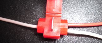
Self-clamping wire connectors
Self-clamping terminal blocks are elements that can be called express terminals. It is very convenient to work with them. You just need to insert the end of the wire into the hole in the device, where it will automatically lock. Fixation is carried out by a clamping bar, the force of which is maintained throughout the entire service life.
It should be noted that this variety is disposable. Of course, you can slowly pull out the wire, but the clamping force will not be the same. Therefore, when replacing wires, terminal blocks of this type are also changed. Fortunately, they are inexpensive, for example, twenty times cheaper than pads.
The most important thing is that such elements inside have a pressure plate made of tinned copper. That is, you can insert both copper and aluminum wires inside. In this case, the clamping surfaces are coated with Vaseline, which prevents the formation of an oxide film on the metal. And it is known to reduce electrical conductivity.
Self-clamping connectors on the market are available in transparent and opaque versions. Plastic does not support combustion in any case.
Self-clamping terminal block made of transparent plastic Source st45.stpulscen.ru
Spring connectors
The lever models mentioned above, also known as spring models, are a housing in which a leaf spring is installed. It is clamped and unclenched with a lever. And we must immediately make a reservation that the market today is simply crowded with products from different manufacturers. Not everyone provides guarantees for the stated parameters. This is especially true for current strength. For example, branded terminals can easily withstand 25 A. Products from unfamiliar companies may not support this characteristic. This means that the terminal block will simply overheat during operation.
Foreign-made terminal blocks
The best manufacturers have developed convenient technologies and innovations that have made it possible to transform classic terminals into unique connection interfaces.
Pressing Push Wire
A one-piece product that uses rigidity properties for reliable fastening. Installation is performed by pushing the stripped end of the wire into the hole. Removal is carried out by unscrewing the wire.
Types of connectors:
- for a single wire;
- for wires with reduced rigidity.
It is almost impossible to pull out the installed wire without damage!
Power spring Power cage clamp
Universal terminal block for all types of electrical wires with a cross-section of up to 95 mm². Consists of a double cage equipped with a spring with a press and a metal tire.
The connection is made using a hexagon for pressing. After installation, the key turns and the lowered press reliably presses the conductor.
Stacked self-clamping Cage clamp
Exclusive technology, patented by WAGO, for conductors of any conductor cross-section up to 35 mm². The connection is made by lifting the spring clamp using a special lever. After installing the conductor, the clamp is lowered back.
terminal block WAGO
Self-clamping Cage clamp S
Use does not involve the use of electrician's tools. The connection is made by installing the bare end of the wire all the way.
Video description
The video shows the design of the WAGO 222 series self-clamping connector:
It should be noted that the lever model is reusable. In principle, it has no other differences from disposable terminal blocks. The manufacturer today offers models that can operate at currents up to 32 A.
Let's add to the advantages of self-clamping and spring designs the fact that during operation the terminals heat up, and accordingly their pressure plate expands. And this increases the downforce of the element.
Spring type connector Source a.allegroimg.com