High voltage testing of electrical equipment is an important part of the design and manufacturing process. Every year the requirements of both customers and relevant standards become more stringent. The role of the testing laboratory as a critical production hub and competitive advantage in the market is increasing.
The essence of most high-voltage tests comes down to checking the electrical strength of the insulation. To perform this check, tests are carried out with increased voltage applied from a separate source. Depending on the type of equipment, the test conditions differ, but one way or another the task comes down to one thing - to apply voltage to the object with the specified characteristics.
If we consider the issue using the example of transformer equipment, then when testing with variable frequency voltage (IEC60076-1,2,3 GOST 1516-3), a voltage source is required that meets the following requirements:
- “good” quality of the sinusoid (non-harmonic distortion coefficient - less than 5%);
- wide range of test voltage levels (for the entire line of equipment);
- test voltage frequency - 50-60 Hz for applied voltage tests and up to 200 Hz for induced voltage tests;
- low level of intrinsic noise of partial discharges (PD).
To implement such a test system, electric machine converters (EMCs) were used for a long time - an electric motor connected by a shaft to an electric generator. Such a voltage source has a number of necessary qualities:
- obtaining an almost ideal sinusoidal voltage at the output, the required frequency, without noise associated with the operation of other network consumers;
- the ability to receive three-phase voltage at the output from a single-phase network;
- filtering current surges due to rotor inertia.
However, such a solution also has a number of significant disadvantages:
- relatively low resource due to the presence of moving parts, the need for periodic repair and maintenance (lubrication of bearings, cleaning of commutators, replacement of brushes in commutator machines);
- long repair period (it is necessary to physically disassemble the device)
- large mass, vibration and noise;
- low efficiency, usually 50–70%, due to double energy conversion;
- increased fire hazard.
It should be noted that when performing induced voltage testing on a transformer, a second test voltage source of higher frequency (200 Hz) will be required. If it is necessary to test equipment designed to operate at a frequency other than 50 Hz, another, additional one may be needed.
An electrical machine converter is a large and noisy piece of equipment. It requires installation on foundations in a separate machine room. In terms of unit mass, the specific power of such a system is about 0.125 MVA per ton of weight. However, a large number of enterprises are still equipped with electrical machine converters, since they have long been the only suitable voltage source for high-voltage test systems.
Despite the fact that semiconductor power converter technology has developed very quickly since its inception, for a long time the industry could not offer a worthy alternative to electrical machine converters for use in high-voltage testing.
In the mid-nineties, SIEMENS AG was one of the first to decide to modernize its testing laboratory in Germany and replace motor-generators (EMGs) of its own production with thyristor converters from the HIGHVOLT company. Then, due to their convenience and versatility, similar systems began to be implemented by other major manufacturers - ABB, SMITH, MITSUBISHI. Modern static frequency converters have become much more powerful, more compact and, importantly, cheaper.
A transformer testing system must be suitable for a wide range of products; the requirements must be met under different characteristics of the test object and test voltages. As a source of test voltage, a static converter is practically free of disadvantages: it operates in a wide frequency range (40–200 Hz) and, accordingly, can replace several generators; in addition, it is much more compact - about 0.5 MVA per ton of weight (in total with control system and switchgear). Thanks to electronic control, in the event of a breakdown of the test object, the converter shutdown speed is up to 10 μs, which is significantly faster than existing EMF-based systems. The consequence of a high shutdown speed is minimal damage to the object, which makes it easier to determine the location of the breakdown, and is in itself safer.
From a technical point of view, there are two main problems in the use of semiconductor converters, the solution to which is, one might say, the know-how of the manufacturers.
The first is the “quality” of the test voltage. Limiting the total harmonic distortion of the test voltage is critical for IEC testing.
For transformer equipment, IEC 60076-1 and 60076-3 define the limit value of harmonic distortion factor as “less than 5%”. How to get the “ideal” sine wave is the military secret of each specific manufacturer. However, an example given by HIGHVOLT at thematic conferences illustrates that even with an extremely non-linear test current, the dynamic characteristics of the converter allow maintaining a stable voltage sinusoid:
The second problem is partial discharge noise. When conducting tests, there are actually two sources of PD: “noise” coming through the network and from the environment, and the converter itself, which is also a source of interference. Moreover, the noise of the converter can be significant. Interference is eliminated in the following ways: by using special converter control circuits, installing filters on the low and high sides of the test system, thereby cutting off both external and internal noise. It should be noted that the standards for PD have become more stringent over the past few years, and further reductions in the permitted level should be expected. The practical limit for PD noise reduction of a test system based on a static converter is 1–2 pC. Such systems exist and are operated in sufficient quantities.
There are other, not so critical, but important differences: converters from different manufacturers differ in power, duration of continuous operation, temperature conditions, size and design.
Another important advantage of a static converter compared to an EMF is the ability (by adjusting the test frequency) to achieve the so-called “self-compensation point”. As is known, an inductor is an oscillatory circuit with a characteristic resonance frequency. At frequencies much lower than the natural resonance frequency, the impedance of the coil is inductive, at frequencies near resonance it is mainly active, and at frequencies above it it is capacitive. When testing with induced voltage at a frequency close to the “self-compensation point”, the requirements for the reactive component of the power of the test system (and/or the capacitor bank used to compensate for it) are significantly reduced. Thanks to this, complete static converter test systems for testing small transformers up to 5000 kVA can be manufactured in a compact module the size of a 10ft container.
System determination of the design option for static voltage converters
The work examines part of the system, namely a unified base cell created on the basis of a voltage inverter circuit powered by rectified network voltage, since this section of the system is the “brick” from which our structure is built.
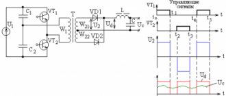
As a basic option, we propose the option of constructing a system of static voltage converters, shown in Fig. 1.
Rice. 1. Sketch of the functional diagram of single-phase and three-phase static voltage converters (SPO and SPT)
The proposed option logically follows from understanding the technical requirements of the task. Let's look at this in more detail. It is necessary to develop a three-phase static voltage converter with a power of 30 kW and a single-phase power converter with a power of 8 kW. The stated task implies the possibility (or even the necessity) of parallel inclusion of some minimal element. If we find the approximate least common multiple, it will be 3.3 kW. That is, the proposed option corresponds to Fig. 1: three three-phase 10 kW units (each with three 3.3 kW subunits) and one single-phase 8 kW unit (consisting of three 3.3 kW subunits with excess power).
The above system allows the use of: deep internal unification; parallel connection of three-phase units (SPT) and single-phase channels (SPO); increasing and decreasing the power of static voltage converters.
Let's consider the above point by point.
- The unification lies in the fact that the SPT and SPO blocks can be assembled on one printed circuit board, with the same mounted elements, with minor changes in switching (mainly in the high-current part) and in the configuration.
- Parallel connection of SPT blocks and SPO channels is possible when using IGBT bipolar transistors with a positive saturation voltage coefficient as power switches. In addition, dynamic current equalization and phase balancing are assigned to the control system. 3. Due to the parallel connection of blocks and channels, the proposed structure for constructing static voltage converters implies the ability to easily increase and decrease the power of static voltage converters. This option is a system for constructing static voltage converters based on a unified base cell (UBC). It is a complete unit that performs the functions of an AC input voltage rectifier, a power factor corrector, a DC voltage stabilizer, a DC-AC voltage converter and an AC output voltage stabilizer (with the function of an output voltage waveform corrector). Another undeniable advantage of this solution is the ability to vary the power of BYU. Accordingly, it is possible to systematically build various families of static voltage converters, covering all functional and parametric series.
A set of control algorithms for a static voltage converter
The proposed set of control algorithms fully confirms the fulfillment of functional requirements. The first link control algorithm, based on a proportional position controller, is shown in Fig. 5.
Rice. 5. Control algorithm based on a positional proportional controller
The algorithm for dynamic control of the output current (Fig. 6) reveals additional functionality:
- dynamic equalization of output current when connected in parallel;
- dynamic regulation of the output current during non-emergency changes.
Rice. 6. Algorithm for dynamic control of output current
The basis is a superposition of two possible options for dynamic changes in the output current: by changing either the value of the intermediate constant voltage or the control coefficient kр. The functional algorithm for regulating the output current by changing the value of the intermediate DC voltage, prepared under the Capture shell, is presented in Fig. 7a.
Rice. 7. Functional algorithm for regulating the output current by changing
The functional algorithm for regulating the output current by changing the control coefficient kр, prepared under the Capture shell, is presented in Fig. 7b.
On
shows a dynamic increase in the output current from 37 to 48 A when the intermediate DC voltage changes from 350 to 450 V.
On
it is shown how a change in the control coefficient kр from 0.4 to 0.9 leads to an increase in the output current from 19 to 41 A.
The control algorithm for the second link based on a self-tuning system, based on sinusoidal pulse-width modulation, is shown in Fig. 10. This algorithm uses the method of stabilizing the output voltage (with the function of correcting the shape of the output voltage), when for each sampling point of the period the output voltage at this point is measured. Using the output voltage data, you can calculate the duration of the PWM signal for the next time slice.
Rice. 10. Control algorithm for a self-tuning system based on sinusoidal pulse width modulation
Description of the operation of a complex of control algorithms in the output voltage shape correction mode
Let's consider the operation of the presented circuit on a capacitive rectifier (
). This type of operation of static voltage converters occurs quite often. But most importantly, this option is characterized by maximum distortion of the output signal shape. Thus, this is the most visual representation of the algorithm’s capabilities in terms of correcting the output voltage shape.
Uncorrected output voltage of the circuit when operating on a capacitive rectifier (Fig. 12).
Rice. 12. Diagrams of the output voltage, PWM signal voltage and output current of the circuit when working on a capacitive rectifier
The figure shows that, despite the correct shape of the PWM signal, the shape of the output low-frequency signal is distorted. This makes it possible to construct a concept for correcting the output voltage waveform based on a change in the PWM signal proportional to the difference between the real signal and the ideal one. The control algorithm uses the method of stabilizing the output voltage (with the function of the output voltage shape corrector), when for each sampling point of the period the output voltage at this point is measured [3].
The presented results prove the viability of the proposed methods.
Using a set of control algorithms to prevent saturation of the output power transformer
The presented set of algorithms helps prevent saturation of the output power transformer core. Indeed, the core is designed so as not to enter the saturation region at the rated value of the output voltage with a margin necessary not only to correct the shape of the output voltage, but also to prevent emergency situations caused by various factors, for example, technological variations in the properties of materials.
As an example, consider the frequently encountered circuit of a bridge voltage inverter with an output power transformer, shown in
.
The control system modeled under the Capture shell in OrCAD 9.2 generates the output voltage shown in Fig. 14, via the PWM signal shown in Fig. 15.
Fig. 14. Output voltage of the simulated circuit
Rice. 15. PWM control signal of the simulated circuit
These figures illustrate the operation of the circuit under uniquely specified conditions. In real conditions, there are many destabilizing factors, so the inverter operating algorithm is aimed at compensating for their influence. However, it should be remembered: within the framework of the main operating algorithm, there is a possibility of reaching saturation of the power transformer (Fig. 16), which can lead to emergency consequences.
Rice. 16. Magnetization curve of the magnetic core of a power transformer
By supplementing the main operating algorithm with a simple protective algorithm (Fig. 17) and using insignificant free resources of the control system, we can avoid undesirable consequences.
Rice. 17. Control algorithm to prevent saturation of the output power transformer
The operating logic of the presented algorithm is based on the principle of self-preservation and provides for the termination of the execution of the main functional section of the algorithm (in this case, possibly correction of the output voltage shape) in order to prevent failure of the entire system. But the additional algorithm does not turn off the system, but somewhat reduces the quality of the output signal to maintain its functionality. In other words, one of the principles inherent in the intellect is used here - the principle of self-preservation.
In reality, this means that when a critical event occurs, the control system stops adjusting the shape of the output voltage and keeps the operation of the static voltage converter in the boundary state, despite distortions in the shape of the output voltage. The case under consideration prevents emergency failure of the output switches and is maintained until the operating conditions of the system change.
Double Conversion Systems
The most common current AC conversion technology is double energy conversion (DEC) systems, which contain a DC link in their structure. The DC link, which provides energy accumulation from the primary AC power source, in addition to reactive elements (capacitance, inductance), may contain a DC voltage regulator RN (lowering or increasing - booster).
The input stage of the converter (rectifier) is separated from the output stage (inverter) by an intermediate DC link. The DC link, in general, contains a significant capacitance designed to smooth out ripples and accumulate the necessary energy to power the inverter. The capacitance value is determined based on ensuring the necessary dynamic properties of the inverter (minimum deviation of the output voltage in transient modes) and the maximum possible overload capabilities of the converter. The capacitance value of the storage capacitors at a DC link voltage of 720-800 V is selected at the rate of 470-660 μF for each 1 kVA of inverter output power to ensure sufficient power supply to the inverter during load surges and dips in the mains voltage. Thus, the DC link has a capacitive character for the input stage (rectifier), which affects the spectral composition of the system input current [3].
Selection of element base, design features of a unified cell and brief analysis
The most critical elements of our circuit are the power switches. This is caused by our chosen conversion frequency of 40 kHz.
Based on this, we choose IGBT bipolar transistors Power MOS 7 from Advanced Power Technology [1].
As our experience in the field of microelectronics shows, the presented technological features effectively act in the indicated directions, which confirms the by no means declarative nature of the declared electrical parameters.
The information provided indicates full compliance of the parameters of IGBT bipolar transistors with the requirements for them in the developed circuit.
The selected algorithms and parameters of the control system, as well as the functional tasks assigned to the system, force us to use a controller with a digital signal processor in the control system. From the point of view of the tasks set, namely, controlling the shape of the output voltage for each PWM quantum, measuring the current of each switch in order to dynamically equalize the currents of parallel-connected subblocks and operating IGBT bipolar transistors at a frequency of 40 kHz, DSPs have an overwhelming advantage.
The most commonly used digital signal processors in secondary power supply control systems are the TMS320 series from Texas Instrument. The TMS320 series DSPs are characterized by high performance and a large number of peripheral devices, which are essential when building control systems for static voltage converters.
However, recently microprocessors with similar characteristics, but cheaper to operate, have appeared.
The cell dimensions are determined by the restrictions imposed on the dimensions in plan (600×600 mm) and height (600 mm).
That is, if the cell fits into the size 19″×19″ = (482.6×482.6 mm), we will fulfill the first requirement and the requirements of international unification. Based on the second requirement and the overall dimensions of the power elements, the cell height should not exceed 150 mm.
The selected circuit solutions and element base allow us to fit into the specified dimensions.
Structurally, the cell is built in a classic way: on the front panel there is a discrete input/output board, a microcontroller and signal switching elements; at the rear there is a radiator with powerful heat-generating elements and powerful switching elements; between them is a board with the rest of the circuit elements. This arrangement, as practice shows, helps solve thermal problems. In addition, modeling electromagnetic processes at the design development stage will allow solving many issues of electromagnetic compatibility. After modeling, SEMIKRON reduced the level of spurious electromagnetic radiation in its smart modules by 2 times [6].
Now let's look at specific power - one of the indicators of modern power electronics voltage converters, which clearly characterizes the quality of the product. The maximum permissible power of our voltage converter is 4000 W. The volume of the block is 4.826×4.826×1.5 = 34.94 dm3. The specific power of our two-stage multifunctional voltage converter is 4000/34.94 = 114.5 (W/dm3), which is quite good by modern standards even for a single-stage voltage converter. In addition, it is possible to double the power while maintaining the same dimensions.
Having examined the results obtained, it can be argued that the developed preliminary design is the basis of a family of static voltage converters of a new generation. This solution not only meets the objectives, but also allows you to significantly expand the area of its use.
Generalization of the results obtained and methods used
The presented option is one of many possible ones. But I would like to highlight some patterns identified during the work and make generalizations:
- Digital, in particular microprocessor-based devices, are becoming increasingly common in control systems of both general and power electronics.
- This allows you to create a number of functionally diverse devices using uniform, optimal circuitry.
- The variety of functions and parameters performed is increasingly determined by the algorithms and software used.
- Algorithmization of control allows not only to achieve new functionality, but also to make the control process visual, logical, simple and reliable.
- The proposed technique is in line with the development of electronics in general.
In conclusion, I would like to note that the considered methodology can be extended not only to other types of power supplies, but also to other types of power electronics, in particular, to drive control.
Literature
- Shchukina I., Nekrasov M. New technology PT IGBT against powerful field-effect transistors // Power Electronics. 2004. No. 1.
- Single-stage power factor corrector // Circuitry. 2001. No. 10.
- Temirev A.P., Fedorov A.E., Masnyuk S.I., Yurin A.V. Algorithm for generating sinusoidal voltage for uninterruptible power supply systems // Power supply. 2003. Vol. 5.
- Silkin V. A. Option for constructing static voltage converters // Components and Technologies. 2004. No. 8.
- Silkin V. A. An example of creating a complex of control algorithms for high-quality static voltage converters // Components and Technologies. 2004. No. 9.
- Silkin V. A. Optimization of electromagnetic compatibility based on 3D mapping and classical theory of circuits with distributed parameters // Components and Technologies. 2005. No. 2.
- Silkin V. A. “Intellectualization” of electronic devices // Components and Technologies. 2005. No. 3.
- Silkin V. A. Draft design of a system of static voltage converters // Modern electronics. 2005. No. 3.
Literature
[1] A. Winter and A. Thiede, A New Generation of On-site Test Systems for power Transformers, International Symposium on Electrical Insulation 2008, Vancouver, Canada, 2008. [2] W. Hauschild; A. Thiede; T. Leibfried; F. Martin, Static frequency converter for high voltage test of power transformer, Stuttgarter Hochspannungssymposium 2006, Stuttgart, Germany, 2006. [3] W. Hauschild ua, the technique of AC on-site testing of HV cables by frequency-tuned resonant test system, Cigre Report 33-304, 2002. [4] IEC 60060-1: 2011: High-voltage test techniques, Part 1: General definitions and test requirements. [5] IEC 60060-2: 2010: High-Voltage Test Techniques Part 2: Measuring systems. [6] IEC 60060-3: 2006: High-voltage test technique. Part 3: Definitions and requirements for on-site testing. [7] IEC 60076-1, Power transformers – Part 1: General, 1997-06. [8] IEC 60076-3, Power Transformer, Part 3: Insulation levels, dielectric tests and external clearances in air, 2000-03. [9] A. Winter and A. Thiede, New Technologies for On-Site Testing of Large Power Transformers, VII International Scientific and Technical Conference “Power Transformers and Diagnostic Systems”, Moscow, 2010.
Pavel KHOTAREV, technical director of RIT LLC The article was published in the magazine “Electrotechnical Market”, No. 4 (58)