Establishing the dependence of current on voltage experimentally
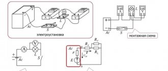
Let's conduct an experiment. Let's assemble an electrical circuit consisting of a current source, a switch, an ammeter, a spiral of nickel wire and a voltmeter (Figure 2).
A spiral of nickel wire will be a kind of conductor, different from other wires. We connect a voltmeter to it in parallel.
Figure 2. Experiment to demonstrate the dependence of current on voltage
The diagram of this electrical circuit is shown in Figure 3. We denote a wire spiral with a rectangle.
Figure 3. Electrical circuit diagram
We close our chain. We record the readings of the ammeter and voltmeter.
Now let's add another current source to our circuit. It will be identical to the first one (Figure 4).
Figure 4. Adding another current source to the circuit
The diagram of such a circuit will look as shown in Figure 5.
Figure 5. Electrical circuit diagram with two current sources
Let's close the circuit. Let's record the instrument readings again.
What will we see if we compare them with the first readings?
The voltage on the spiral doubled. The current strength also doubled.
If we add a third current source to the circuit, we will see an increase in current and voltage not two, but three times. Let's add a fourth current source - we will see an increase in both readings by four times, etc.
Resistors, current and voltage
In this article we will look at a resistor and its interaction with the voltage and current passing through it. You will learn how to calculate a resistor using special formulas. The article also shows how special resistors can be used as a light and temperature sensor.
The idea of electricity
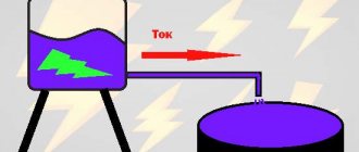
A beginner should be able to imagine electric current. Even if you understand that electricity consists of electrons moving through a conductor, it is still very difficult to visualize clearly. That's why I offer this simple analogy with a water system that anyone can easily imagine and understand without delving into the laws.
Notice how electric current is similar to the flow of water from a full tank (high voltage) to an empty tank (low voltage). In this simple analogy of water and electric current, a valve is analogous to a current limiting resistor. From this analogy we can derive some rules that you must remember forever: - As much current flows into a node, so much flows out of it - In order for current to flow, there must be different potentials at the ends of the conductor. — The amount of water in two vessels can be compared to the charge of a battery. When the water level in different vessels becomes the same, it will stop flowing, and when the battery is discharged, there will be no difference between the electrodes and the current will stop flowing. - The electric current will increase as the resistance decreases, just as the speed of water flow will increase as the valve resistance decreases.
I could write many more inferences based on this simple analogy, but they are described in Ohm's law below.
Resistor
Resistors can be used to control and limit current, hence the main parameter of a resistor is its resistance, which is measured in Ohms . We should not forget about the power of the resistor, which is measured in watts (W), and shows how much energy the resistor can dissipate without overheating and burning out. It is also important to note that resistors are not only used to limit current, they can also be used as a voltage divider to produce a lower voltage from a higher voltage. Some sensors are based on the fact that resistance varies depending on illumination, temperature or mechanical impact; this is written in detail at the end of the article.
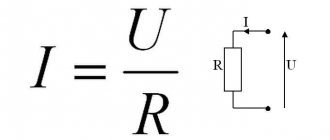
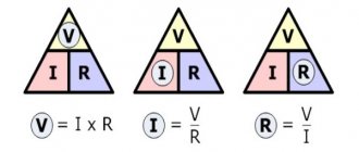
Ohm's law
It is clear that these 3 formulas are derived from the basic formula of Ohm's law, but they must be learned to understand more complex formulas and diagrams. You should be able to understand and imagine the meaning of any of these formulas. For example, the second formula shows that increasing the voltage without changing the resistance will lead to an increase in current. However, increasing the current will not increase the voltage (even though this is mathematically true) because voltage is the potential difference that will create electric current, not the other way around (see the 2 water tank analogy). Formula 3 can be used to calculate the resistance of a current limiting resistor at a known voltage and current. These are just examples to show the importance of this rule. You will learn how to use them yourself after reading the article.
Series and parallel connection of resistors
Understanding the implications of connecting resistors in parallel or in series is very important and will help you understand and simplify circuits with these simple formulas for series and parallel resistance:
In this example circuit, R1 and R2 are connected in parallel, and can be replaced by a single resistor R3 according to the formula: In the case of 2 resistors connected in parallel, the formula can be written as follows:
In addition to being used to simplify circuits, this formula can be used to create resistor values that you don't have. Note also that the value of R3 will always be less than that of the other 2 equivalent resistors, since adding parallel resistors provides additional paths for electrical current, reducing the overall resistance of the circuit.
Series-connected resistors can be replaced by a single resistor, the value of which will be equal to the sum of these two, due to the fact that this connection provides additional current resistance. Thus, the equivalent resistance R3 is very simply calculated: R3=R1+R2
There are convenient online calculators on the Internet for calculating series and parallel connections of resistors.
Current limiting resistor
The most basic role of current limiting resistors is to control the current that will flow through a device or conductor. To understand how they work, let's first look at a simple circuit where the lamp is directly connected to a 9V battery. A lamp, like any other device that consumes electricity to perform a specific task (such as emitting light), has an internal resistance that determines its current consumption. Thus, from now on, any device can be replaced by an equivalent resistance.
Now that the lamp will be considered as a resistor, we can use Ohm's law to calculate the current passing through it. Ohm's law states that the current passing through a resistor is equal to the voltage difference across it divided by the resistance of the resistor: I=V/R or more precisely: I=(V1-V2)/R where (V1-V2) is the voltage difference to and after the resistor.
Now look at the picture above where a current limiting resistor has been added. It will limit the current going to the lamp, as the name suggests. You can control the amount of current flowing through the lamp simply by selecting the correct R1 value. A large resistor will reduce the current greatly, while a small resistor will reduce the current less strongly (same as in our water analogy).
Mathematically it will be written like this:
It follows from the formula that the current will decrease if the value of R1 increases. Thus, additional resistance can be used to limit the current. However, it is important to note that this causes the resistor to heat up, and you must correctly calculate its power, which will be discussed later.
You can use an online calculator to calculate the current limiting resistor of an LED.
Resistors as a voltage divider
As the name suggests, resistors can be used as a voltage divider, in other words, they can be used to reduce voltage by dividing it. Formula:
If both resistors have the same value (R1=R2=R), then the formula can be written as follows:
Another common type of divider is when one resistor is connected to ground (0V), as shown in Figure 6B. Replacing Vb with 0 in formula 6A, we get:
Nodal analysis
Now, when you start working with electronic circuits, it is important to be able to analyze them and calculate all the necessary voltages, currents and resistances. There are many ways to study electronic circuits, and one of the most common methods is the nodal method, where you simply apply a set of rules and calculate, step by step, all the necessary variables.
Simplified rules for nodal analysis
Node Definition
A node is any connection point in a chain. Points that are connected to each other, without other components in between, are treated as a single node. Thus, an infinite number of conductors to one point are considered one node. All points that are grouped into one node have the same voltages.
Branch Definition
A branch is a collection of 1 or more components connected in series, and all components that are connected in series to that circuit are considered as one branch.
All voltages are usually measured relative to ground, which is always 0 volts.
Current always flows from a node with a higher voltage to a node with a lower one.
The voltage at the node can be calculated from the voltage near the node, using the formula: V1-V2=I1*(R1) Let's move: V2=V1-(I1*R1) Where V2 is the desired voltage, V1 is the reference voltage, which is known, I1 current flows from node 1 to node 2 and R1 represents the resistance between the 2 nodes.
In the same way as in Ohm's law, the branch current can be determined if the voltage of 2 adjacent nodes and the resistance is known: I 1 = (V1-V2)/R1
The current input current of a node is equal to the current output current, so it can be written as: I 1+ I3=I2
It is important that you are able to understand the meaning of these simple formulas. For example, in the figure above, current flows from V1 to V2, and therefore the voltage of V2 should be less than V1. By using the appropriate rules at the right time, you can quickly and easily analyze and understand the circuit. This skill is achieved through practice and experience.
Calculation of the required resistor power
When purchasing a resistor, you may be asked the question: “What power resistors do you want?” or they can just give 0.25W resistors as they are the most popular. As long as you are working with resistances greater than 220 ohms and your power supply is providing 9V or less, you can work with 0.125W or 0.25W resistors. But if the voltage is more than 10V or the resistance value is less than 220 ohms, you must calculate the power of the resistor, or it may burn out and ruin the device. To calculate the required resistor power, you must know the voltage across the resistor (V) and the current flowing through it (I): P=I*V where current is measured in amperes (A), voltage in volts (V) and P is power dissipation in watts (W)
The photo shows resistors of various powers, they mainly differ in size.
Types of resistors
Resistors can be different, ranging from simple variable resistors (potentiometers) to ones that respond to temperature, light and pressure. Some of them will be discussed in this section.
Variable resistor (potentiometer)
The above figure shows a schematic representation of a variable resistor. It is often referred to as a potentiometer because it can be used as a voltage divider.
They vary in size and shape, but they all work the same way. The terminals on the right and left are equivalent to a fixed point (such as Va and Vb in the figure above left), and the middle terminal is the moving part of the potentiometer and is also used to change the resistance ratio of the left and right terminals. Therefore, a potentiometer is a voltage divider that can be set to any voltage from Va to Vb. Additionally, a variable resistor can be used as a current limiting resistor by connecting the Vout and Vb pins as in the figure above (right). Imagine how the current will flow through the resistance from the left terminal to the right until it reaches the moving part, and flows along it, while very little current flows to the second part. So you can use a potentiometer to adjust the current of any electronic components, such as a lamp.
LDR (Light Sensing Resistors) and Thermistors
There are many resistor-based sensors that respond to light, temperature or pressure. Most of them are included as part of a voltage divider, which varies depending on the resistance of the resistors, which changes under the influence of external factors.
Thermistors
Photoresistor (LDR)
As you can see in Figure 11A, photoresistors vary in size, but they are all resistors whose resistance decreases when exposed to light and increases in darkness. Unfortunately, photoresistors react rather slowly to changes in light levels and have fairly low accuracy, but are very easy to use and popular. Typically, the resistance of photoresistors can vary from 50 ohms in the sun, to more than 10 megohms in absolute darkness.
As we already said, changing the resistance changes the voltage from the divider. The output voltage can be calculated using the formula:
If we assume that the LDR resistance varies from 10 MΩ to 50 Ω, then Vout will correspondingly be from 0.005V to 4.975V.
A thermistor is similar to a photoresistor, however, thermistors have many more types than photoresistors, for example, a thermistor can be either a negative temperature coefficient (NTC) thermistor, whose resistance decreases with increasing temperature, or a positive temperature coefficient (PTC), whose resistance will increase with increasing temperature. Now thermistors respond to changes in environmental parameters very quickly and accurately.
Circuit designation of resistors
You can read about determining the resistor value using color coding here.
Original article
Tags:
- Translation
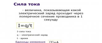
Graph of current versus voltage
What does the graph of current versus voltage look like?
An example of such a graph is shown in Figure 6. This is a direct proportionality graph. The straight line describing it passes through the origin of coordinates. The horizontal axis shows voltage values, and the vertical axis shows current values.
Figure 6. Graph of current versus voltage
What relationship between quantities does it reflect?
Such a graph reflects the directly proportional relationship between these two quantities: current and voltage. That is, by how many times we increase the voltage at the ends of the conductor, the current strength in it will increase by the same amount.
Decluttering and Reusing
A burned out LED should be thrown away. Everything else can be used again.
| Basic information |
| Origin of the concept of power James Watt is known as the inventor of the steam engine. He was born in 1736 in Scotland, where he set up a small workshop at the University of Glasgow and developed an efficient design for using steam to move a piston in a cylinder. Financial problems and the primitive state of metalworking technology delayed the practical implementation of the invention until 1776. Despite the difficulties in obtaining patents (which could only be granted by parliamentary action at the time), Watt and his business partner ended up making a lot of money from their innovations. Although he lived before the founders of electricity, in 1889 (70 years after his death), his name was given to the basic unit of electrical power, which in direct current electrical circuits can be defined as the product of current in amperes and voltage in volts |
| Fundamentals |
| Basics of Watts Until now, I have not said anything about a unit of measurement that everyone is probably familiar with - watts. Watt is a unit for measuring work. Engineers have their own definition of work - they say that work can be done by a person, animal or machine that acts on something to overcome mechanical resistance. An example would be a steam engine pulling a train along a horizontal track (overcoming friction and air resistance), or a person climbing a ladder (overcoming gravity). When electrons make their way through a circuit, they also overcome some resistance and therefore do work, which can be measured in watts. There is a very simple definition: watts = volts × amps Using the usual notation used, three formulas can be given that basically mean the same thing: W = U × I.U = W/I.I = W/U.For watts, the abbreviated international designation “W” is used, in Russian the designation “W”. Together with the abbreviated designations watts, various prefixes can be used, such as “m” to designate “milli” - “mW” (in Russian designation “mW”), however, exactly the same as in the case of using volts or ampere ( Table 2 ). Table 2.
Table 3. The power of incandescent light bulbs is expressed in watts. The power of a stereo system is measured in similar units. Watt was named after James Watt, who invented the steam engine. By the way, watts can be converted to horsepower and vice versa. |
Exercises
Exercise No. 1
When the voltage at the ends of the circuit section is equal to $2 \space V$, the current strength in the conductor is $0.4 \space A$.
What should the voltage be so that the current in the same conductor is $0.8 \space A$? Given: $U_1 = 2 \space B$ $I_1 = 0.4 \space A$ $I_2 = 0.8 \space A$
$U_2 — ?$
Show solution and answer
Hide
Solution:
We know that voltage and current are directly proportional to each other . This means that by how many times the current strength increases, the voltage will increase by the same amount.
Let's see how many times the current strength has increased: $\frac{I_2}{I_1} = \frac{0.8 \space A}{0.4 \space A} = 2$.
It turns out that the current strength has doubled. This means that the voltage will also double: $U_2 = 2 \cdot U_1 = 2 \cdot 2 \space V = 4 \space V$.
Answer: $U_2 = 4 \space В$.
Ohm's law for a circuit section
Let's assemble an electrical circuit (Figure 1, a), consisting of a battery 1 with a voltage of 2 V, a lever rheostat 2, two measuring instruments - a voltmeter 3 and an ammeter 4 and connecting wires 5. Using a rheostat, we install a resistance in the circuit equal to 2 Ohms. Then a voltmeter connected to the battery terminals will show a voltage of 2 V, and an ammeter connected in series to the circuit will show a current of 1 A. Let’s increase the voltage to 4 V by connecting another battery (Figure 1, b). With the same resistance in the circuit - 2 Ohms - the ammeter will show a current of 2 A. A battery with a voltage of 6 V will change the ammeter reading to 3 A (Figure 1, c). Let's summarize our observations in Table 1.
Figure 1. Changing the current in an electrical circuit by changing the voltage with a constant resistance
Table 1
Dependence of current in a circuit on voltage with constant resistance
| Circuit voltage in V | Circuit resistance in ohms | Circuit current in A |
| 2 4 6 | 2 2 2 | 1 2 3 |
From this we can conclude that the current in a circuit with constant resistance is greater, the greater the voltage of this circuit, and the current will increase as many times as the voltage increases.
Now in the same circuit we will place a battery with a voltage of 2 V and, using a rheostat, set the resistance in the circuit to 1 Ohm (Figure 2, a). Then the ammeter will show 2 A. Let's increase the resistance to 2 Ohms with a rheostat (Figure 2, b). The ammeter reading (at the same circuit voltage) will be already 1 A.
Figure 2. Changing the current in an electrical circuit by changing the resistance at a constant voltage
If the resistance in the circuit is 3 ohms (Figure 2, c), the ammeter reading will be 2/3 A.
We summarize the results of the experiment in Table 2.
table 2
Dependence of current in a circuit on resistance at constant voltage
| Circuit voltage in V | Circuit resistance in ohms | Circuit current in A |
| 2 2 2 | 1 2 3 | 2 1 2/3 |
It follows from this that at a constant voltage the current in the circuit will be greater, the lower the resistance of this circuit, and the current in the circuit increases as many times as the resistance of the circuit decreases.
As experiments show, the current in a section of a circuit is directly proportional to the voltage in this section and inversely proportional to the resistance of the same section. This relationship is known as Ohm's law.
If we denote: I – current in amperes; U – voltage in volts; r is the resistance in ohms, then Ohm’s law can be represented by the formula:
that is, the current in a given section of the circuit is equal to the voltage in that section divided by the resistance of the same section.
Video 1. Ohm's law for a section of a circuit
Example 1. Determine the current that will flow through the filament of an incandescent lamp if the filament has a constant resistance of 240 Ohms and the lamp is connected to a network with a voltage of 120 V.
Using the formula of Ohm's law, you can also determine the voltage and resistance of the circuit.
U = I × r,
that is, the voltage of the circuit is equal to the product of the current and the resistance of this circuit and
that is, the circuit resistance is equal to the voltage divided by the circuit current.
Example 2. What voltage is needed for a current of 20 A to flow in a circuit with a resistance of 6 Ohms?
U = I × r = 20 × 6 = 120 V.
Example 3. A current of 5 A flows through the spiral of an electric stove. The stove is connected to a network with a voltage of 220 V. Determine the resistance of the spiral of the electric stove.
If in the formula U = I × r the current is 1 A and the resistance is 1 Ohm, then the voltage will be 1 V:
1 V = 1 A × 1 Ohm.
From this we conclude: a voltage of 1 V acts in a circuit with a resistance of 1 Ohm at a current of 1 A.