One of the electronic devices widely used in various circuits is the rectifier diode, with the help of which alternating current is converted into direct current. Its design is created in the form of a two-electrode device with one-way electrical conductivity. AC rectification occurs at metal-semiconductor and semiconductor-metal junctions. Exactly the same effect is achieved in electron-hole transitions of some crystals - germanium, silicon, selenium. These crystals are in many cases used as the main elements of devices.
General characteristics and operating principle
Rectifier diodes are capable of making and breaking circuits, as well as switching electrical signals. Their operating principle is based on certain features of the pn junction. The bottom line is that each diode has two leads or electrodes. One of them is the anode, and the second is the cathode. The anode is connected to the p-layer, and the cathode is adjacent to the n-layer.
Between the p- and n-layer there is a small region without mobile charge carriers, which has high electrical resistance. This is called the barrier layer and defines the potential barrier.
When an external voltage is applied to the pn junction, creating an electric field directed opposite to the field of the blocking layer, then this layer begins to decrease in thickness. It finally disappears at a voltage of 0.4–0.6 Volts. In this case, the current, which is called direct, increases significantly.
Applying external power of a different polarity leads to an increase in the blocking layer and an increase in the resistance of the pn junction. In this case, the current is created by minority charge carriers. It will have an insignificant value even at a relatively high voltage.
Consequently, the forward current is created by the majority charge carriers, and the reverse current is created by the minority charge carriers. Rectifier diodes pass direct (positive) electric current in the direction from the anode to the cathode.
How a rectifier diode works is most easily explained using a simple half-wave rectifier circuit.
The diode half-wave rectifier remains in the open position during the positive half-cycle, so current passes through it and enters the load. During the negative half-cycle, the diode is turned off and no voltage is supplied to the load. As a result, the output receives pulses that consist only of positive half-cycles and are called direct current.
Circuit of a simple AC rectifier using one diode.
Let us analyze the operation diagram of the simplest rectifier, which is shown in the figure:
variable to the input of the rectifier
voltage, in which
positive
half-cycles are highlighted in red and
negative
are highlighted in blue.
Rн
to the output of the rectifier
VD
will perform the function of the rectifying element .
With positive
half cycles of voltage supplied to the anode of the diode, the diode
opens
.
current
Ipr
through the diode, and therefore through the load ( Rн
), powered by the rectifier
wave is shown in red in the right graph).
For negative
Half cycles of voltage supplied to the anode of the diode, the diode
closes
diode
current Irev
will flow throughout the entire circuit .
Here, the diode seems to cut off the negative
half-wave of the alternating current (in the right graph, such a half-wave is shown by a blue dotted line).
As a result, it turns out that through the load ( Rн
), connected to the network through a diode (
VD
), the flow is no longer alternating, since this current flows only in positive half-cycles, and
the pulsating
current is a current of one direction. This is AC rectification.
But this voltage can only power a low-power load that is powered by an AC mains and does not have any special power requirements, for example, an incandescent lamp. Voltage will only pass through the lamp during positive half-waves (pulses), so the lamp will flicker faintly at a frequency of 50 Hz. However, due to thermal inertia, the filament will not have time to cool down in the intervals between pulses, and therefore the flickering will be faintly noticeable.
If we power a receiver or power amplifier with this voltage, then in the loudspeaker or speakers we will hear a low-pitched hum with a frequency of 50 Hz, called AC hum
. This will happen because the pulsating current, passing through the load, creates a pulsating voltage in it, which is the source of the background.
This drawback can be partially eliminated if in parallel
connect a high-capacity filtering
electrolytic capacitor
(Cf) to the load.
Charging by current pulses during positive half-cycles, the capacitor ( Cph
) during negative half-cycles
it is discharged
through the load (
Rн
).
If the capacitor is of sufficiently large capacity, then during the time between current pulses it will not have time to be completely discharged, which means that the current will be continuously maintained at the load ( Rн
) both during positive and negative half-cycles. The current maintained by charging the capacitor is shown in the right graph as a solid wavy red line.
But even with such a somewhat smoothed current, it is also impossible to power a receiver or amplifier because they will “phon”, since the ripple level ( Upulse
) is still very noticeable.
half
of the alternating current waves
is usefully used the input
voltage is lost on it and therefore such rectification of alternating current is called
half-wave
, and rectifiers are
half-wave rectifiers
.
These shortcomings are eliminated in rectifiers using a diode bridge
.
Types of diodes
The main element of a rectifying diode is a semiconductor. Most often, a silicon or germanium crystal is used as it. Silicon diodes are used more often than germanium diodes. This is due to the fact that the latter are characterized by a higher value of reverse currents, which significantly limits the permissible value of reverse voltage. For germanium semiconductors, this figure does not exceed 400 Volts. For silicon diodes, the maximum reverse voltage can reach 1500 Volts.
In addition, silicon semiconductors have higher operating temperatures. But this advantage is also associated with a significant disadvantage of these radioelements. If the reverse voltage leads to their breakdown, then it is thermal in nature. This means that a broken silicon rectifier almost always needs to be replaced with a new one.
The advantage of germanium is a small voltage drop during direct electric current.
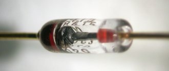
Depending on the manufacturing technology, semiconductor diodes are divided into point and planar. The first ones consist of a small n-type plate and a steel needle, which creates a pn junction at the contact point. The main structural elements of planar semiconductor diodes are two plates of different electrical conductivity connected together.
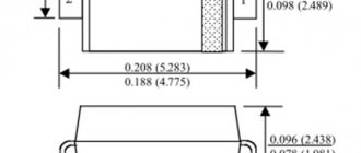
The maximum permissible forward current determines the power of the rectifier diodes. Based on this characteristic, they are usually divided into:
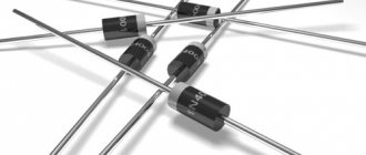
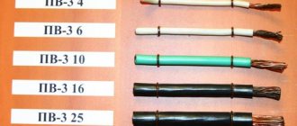
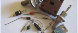
- Low current. They are small in size and light in weight. They are produced mainly in plastic cases. The rectified current does not exceed 0.3 Ampere.
- Medium power diodes. Their cases are made of metal, and on one of the terminals (cathode) there is a thread, with which the radio element can be securely fixed to the radiator used for heat removal. Capable of rectifying alternating current from 0.3 to 10 Amps.
- Power semiconductor rectifiers. Designed for direct current exceeding 10 A. They are produced in metal-ceramic or metal-glass housings of tablet or pin type.
There are also such types of rectifier diodes as:
- Pulse. They are used in low-power electronic circuits. Their main feature is the short time spent on the transition from a closed state to an open state, and vice versa. This is approximately 100 microseconds.
- Converts. When switched on in reverse, they offer little resistance to the passing current and much more when switched on directly. Reversed diodes are designed primarily for rectifying small signals with a voltage amplitude of no more than 1 Volt.
- Schottky rectifiers. They have low resistance, so they are used to rectify significant currents, reaching tens of amperes. Thermal energy does not accumulate inside Schottky rectifiers, so there is no resorption of minority carriers of electric charges.
- Zener diodes. Capable of maintaining all their performance characteristics even in electrical breakdown mode. Abroad they are called Zener diodes.
- Diode bridge. This circuit is assembled from four elements. Used to improve the quality of AC to DC conversion. It differs in that it is capable of passing current during each half-cycle. Bridges are produced in the form of a device enclosed in a plastic housing.
All types of rectifier diodes differ in appearance, but their choice is simplified by the corresponding designation printed on the case. Catalogs with markings and UGOs for these semiconductor elements are presented in a special reference book. It should be noted that the marking of imported diodes differs from domestic ones. The alphanumeric designation of domestic diodes is regulated by OST 11366.919-81. The explanation of the marking according to this document is presented in the figure below.
Therefore, if the case is marked KD202A, then it will be a medium-power silicon rectifier diode of version A.
There are also requirements regarding conventional graphic images of diodes on diagrams.
Device
A semiconductor diode is a two-terminal device made from a semiconductor substance that allows current to pass in one direction and virtually no current in the other.
The main element of the diode is a crystalline component with a pn junction, to which a metal anode and a cathode are soldered (welded). The passage of direct current is carried out when a positive potential, relative to the cathode, is applied to the anode.
Note! Holes move in the direction of forward current. The electrons move in the opposite direction
The diode design can be point, planar, or polycrystalline.
Device of a point and planar p/p device
Additional Information. There are no fundamental differences between point and planar bipolar devices.
The structure of a point diode is shown in figure (a).
When a thin needle, with an impurity deposited on it, is welded to a semiconductor plate with a certain type of electrical conductivity, a hemispherical mini pn junction with a different type of conductivity is formed. This action is called diode forming.
The production of a planar two-terminal network is carried out by the diffusion fusion method. Figure (b) shows an alloy germanium diode and the principle of its design. In a plate of n-type germanium, when a drop of indium is fused there at 500 degrees, a layer of p-type germanium is formed. The lead contacts soldered to the germanium and indium base plate are made of nickel.
Germanium, silicon, gallium arsenide and carbide are used in the production of semiconductor wafers. Semiconductor monocrystalline wafers with a correct structure throughout the entire volume are used as the basis for point and planar two-terminal networks.
In polycrystalline two-terminal networks, the pn junction is formed by semiconductor layers, which include a large number of randomly oriented small crystals that do not represent a single single-crystalline form. These are selenium, titanium and copper oxide bipolars.
Diode rectifier parameters
Each type of diode has its own maximum permissible and performance characteristics. The main parameters of rectifier diodes are presented in the table:
As a rule, this information is accessed when an element from the rectifier circuit is unavailable and a replacement needs to be found. In most cases, analogues are selected according to the first five parameters from the table, but sometimes it is also necessary to take into account such characteristics of rectifier diodes as operating temperature and frequency.
A very important parameter of diodes is their forward current. It should be taken into account when replacing the original diodes with analogues, as well as in the case of creating homemade devices. Depending on various modifications, forward current values can reach values of several tens and even hundreds of amperes. Therefore, in powerful devices, diode bridges must be installed in a special housing together with a cooling radiator, which does not allow the crystal in the diode to overheat.
Some subtypes of diodes, such as Schottky, are very susceptible to reverse voltage surges and can therefore quickly become unusable. But silicon semiconductors, on the contrary, are resistant to increases in reverse voltage. They can last for a long period, namely until the crystal on the conductor overheats and fails, which takes a lot of time.
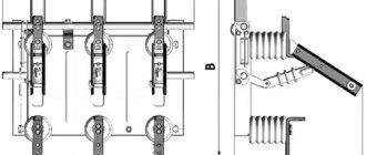
Thyristors.
Three-electrode thyristors (thyristors) are semiconductor devices used to regulate power in AC and DC networks. The thyristor easily transitions from a closed (non-conducting) state to an open state when an opening pulse is applied to the control electrode. Once the thyristor is turned on, it remains in this state until the current flowing through it decreases to a certain threshold value.
When working in alternating current circuits, a similar decrease occurs with each change of polarity, with a change in phase. In DC circuits, special circuits are used to disconnect.
Volt-ampere characteristics
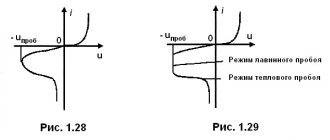
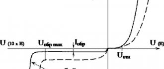
In practice, the calculated values do not always completely coincide with the theoretical basic parameters of semiconductor elements. For example, the current-voltage characteristic of the rectifier diode used or the current-voltage characteristic depends on the movement of electric current in the conductor in the forward and reverse directions. The value of the forward current is an order of magnitude greater than the reverse, and the value of the forward voltage is an order of magnitude less. When the reverse voltage reaches its threshold value, the reverse current increases sharply and breakdown of the pn layer occurs.
The dependences of forward and reverse currents and voltages can be presented in the form of a graph. It consists of two branches - forward and reverse. The straight line is located in the first quadrant and reflects the maximum conductivity of the diode at forward voltage. Reverse is in the third quadrant and corresponds to low conductivity at reverse voltage. At low conductivity, current does not pass through the semiconductor.
The current-voltage characteristic of a rectifying semiconductor diode depends on temperature. As this parameter increases, the forward voltage decreases. Such properties of the graph as sharp asymmetry are also important. The displacement of the forward branch indicates high conductivity, and the displacement of the reverse branch indicates low conductivity.
In areas with high potential differences, the dependence of current on voltage becomes almost linear.
Manufacturing technology
The design of a rectifying diode is a wafer of a semiconductor crystal, in the body of which there are two regions with different conductivities. This is the reason why they are called planar.
Semiconductor rectifier diodes are made like this: in the region of the semiconductor crystal with n-type conductivity, aluminum, indium or boron is melted, and in the region of the crystal with p-type conductivity, phosphorus is melted.
When exposed to high temperatures, these two substances are firmly fused to the semiconductor base. In addition, the atoms of these materials diffuse into the crystal to form a region with predominantly electronic or hole conductivity. As a result, a semiconductor device is formed that has two regions with different types of electrical conductivity, and a pn junction is formed between them. This is the operating principle of the vast majority of planar diodes made of silicon and germanium.
Where is it used in practice?
With the development of scientific and technological progress, the use of rectifier diodes has become a necessity. They are used in such units and mechanisms as:
- Power supplies for engines of land, water and air vehicles, industrial machines, drilling rigs.
- Diode bridges for welding machines.
- Rectifier installations for galvanic baths.
- Installations for air and water purification.
- High voltage transmission lines.
Rectifier circuits are divided into single-phase and multiphase, half-wave and full-wave. The simplest full-wave circuit can be built on the basis of two half-wave circuits. In such a rectifier circuit there are two diodes and one resistor. If you use not two, but four diodes, then the efficiency will increase significantly.
The quality of the rectifier is reflected by the rectification factor. Its value is determined by the ratio of forward and reverse currents. The higher the coefficient, the better the rectifier does its job.
Diodes are used in practice not only as rectifiers, but also as detectors. It is very easy to construct working signal limiters from diode rectifiers. To do this, you need to connect two diodes in parallel. In this position, they will act as excellent and effective protection for the amplifier input. For example, this method is used for a microphone amplifier, as it helps to maximize the quality and level of the signal.
Diodes are integrated into logic devices, as well as walkie-talkies, baby monitors and other switches whose task is to transmit clear, uninterrupted remote signals.
LEDs are also in demand at the moment. A few decades ago they were used only as indicators inside various devices. Today, both simple devices such as hand-held flashlights and more complex equipment, such as LCD TVs, are equipped with LEDs.
To summarize, we can say that modern rectifier diodes are available in a wide range. They differ in both their design and performance characteristics. When choosing the right radio element, you should be guided by the data given in the reference manuals.
Voltage stabilization and Zener diodes.
The output voltage of a conventional, unregulated direct current source is subject to fluctuations due to changes in the voltage at its input. Drawing. When connecting different consumers consuming different currents, the voltage also changes - it increases with less load, falls with more. For normal operation of electronic devices, it is necessary to stabilize this voltage, making its value independent of the above-mentioned factors. Zener diodes are semiconductor diodes used to stabilize voltage in various power supplies. Unlike conventional diodes, they operate when turned on in reverse, in breakdown mode. This does not harm them if the power dissipation limit is not exceeded, the value of which is a derivative of the voltage drop across the junction and the current flowing through it.
So, the most important parameters of a zener diode are the stabilization voltage and the maximum operating current. The operating current of the zener diode is limited by a series-connected resistor.
Rectification factor
Analyzing the device characteristics, it should be noted: such quantities as the rectification coefficient, resistance, and capacitance of the device are taken into account. These are differential parameters.
It reflects the quality of the rectifier.
It can be calculated: it will be equal to the ratio of the forward current of the device to the reverse one. This calculation is acceptable for an ideal device. The value of the rectification coefficient can reach several hundred thousand. The larger it is, the better the straightener does its job.