A thermocouple is a pair of conductor-electrodes made of dissimilar alloys, the ends of which are free on one side and joined (soldered) together on the other. When a soldered section is immersed in a particular medium with a certain temperature T1, the so-called thermoelectric Seebeck effect occurs: due to differences in thermal characteristics, the conductors react to the temperature of the medium differently, and the temperature T2 at their free ends turns out to be different. As a result, a thermoelectromotive force (thermo-EMF) based on the potential difference arises and, as a consequence, an electric current, the voltage of which will be proportional to the temperature difference T1/T2. The proportionality coefficient is called the thermo-EMF coefficient. If you connect an electrical measuring device (millivoltmeter) that closes the circuit to the free ends of the electrodes, then according to the arrow readings on a graduated scale, it will be possible to measure changes in the temperature characteristics of the medium in which the thermocouple joint is immersed. Thus, a thermocouple complete with an electrical measuring device is nothing more than a thermoelectric thermometer.
Such devices are widely used in measuring temperature indicators of various objects, as well as as part of automated control/monitoring systems. Due to the high degree of linearity, low inertia, simplicity of design/installation, low cost and the ability to make measurements in a wide temperature range (from -250 °C to +2500 °C), incl. in aggressive environments, they are used almost everywhere today.
Chromel-alumel type K
This is one of the most used types of thermocouples.
Over a long period of time it measures temperatures up to 1100 0C, in a short time – up to 1300 0C. Measuring low temperatures is possible down to -200 0C. Performs well in oxidizing atmospheres and inert conditions. Can be used in dry hydrogen, and briefly in a vacuum. Sensitivity – 40 µV/ 0С. This is the most resistant type of thermocouple capable of operating in reactive conditions. The disadvantages are high deformation of the electrodes and unstable EMF.
Chromel-alumel or K-type thermocouple are not used in environments containing more than 3% O2. With a higher oxygen content, chromium is oxidized and the thermal emf decreases. Type K with protective cover can be used in a variable redox atmosphere.
To protect the XA thermocouple, a shell made of porcelain, asbestos, fiberglass, quartz, enamel material or highly refractory oxides is used.
Most often, chromel-alumel fails due to the destruction of the alumel electrode. This happens after heating the electrode to 650 degrees in a sulfur environment. Corrosion of alumel can be prevented only by eliminating the entry of sulfur into the working environment of the thermocouple.
Chrome deteriorates due to internal oxidation when the atmosphere contains water vapor or high acidity. Protection is the use of ventilated protection.
Literature
- Thermocouple // Lake Teletskoye - Trichophytosis. - M.: Soviet Encyclopedia, 1946. - (: / chief editor O. Yu. Shmidt; 1926-1947, vol. 54).
- Keyes R. J., Kruse P. W., Patley E. G., Long D., Zwicker G. R., Milton A. F., Teich M. K.
§ 3.2. Thermocouple // Photodetectors of the visible and IR ranges = Optical and Infrared Detectors / trans. from English edited by V. I. Stafeeva. - M.: Radio and Communications, 1985. - 328 p.
H. Melloni. Ueber den Durchgang der Wärmestrahlen durch verschiedene Körper (German) // Annalen der Physik und Chemie: journal. - Leipzig: Verlag von Johann Ambrosius Barth, 1833. - Bd. 28. - S. 371-378.
Grunin V.K. § 2.3.4. Thermoelectric radiation receivers // Sources and receivers of radiation: textbook. - St. Petersburg: Publishing house of St. Petersburg Electrotechnical University "LETI", 2015. - 167 p. — ISBN 978-5-7629-1616-5.
Chromel-copel type L
It is also a commonly used thermocouple allowing measurements in inert and oxidizing environments.
Long-term measurement up to 800 0С, short-term – 1100 0С. The lower limit is -253 0C. Long-term operation up to 600C. This is the most sensitive thermocouple of all industrial-type measuring devices. Has linear graduation. At a temperature of 600 degrees it is distinguished by thermoelectric stability. The disadvantage is the increased susceptibility of the electrodes to deformation. The positive electrode of a type L thermocouple is chromel, and the negative electrode is kopel. The working medium is oxidizing or with an inert gas component. Can be used in vacuum at elevated temperatures for a short time. Using good gas-tight protection, THC can be used in sulfur-containing and oxidizing environments. Operation in a chlorine or fluorine-containing atmosphere is possible, but only up to 200 degrees.
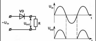
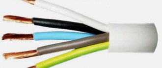
Thermocouple connection diagram
- Connecting a potentiometer or galvanometer directly to the conductors.
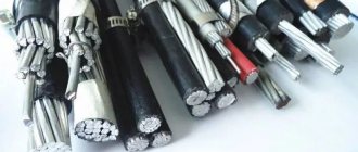
- Connection using compensation wires;
- Connection with ordinary copper wires to a thermocouple with a unified output.
Iron constantan type J
Used in reducing, oxidizing, inert and vacuum environments.
Measurement of positive media up to 1100 0С, negative – up to -203 0С. It is type J that is recommended for use in a positive environment with a transition to negative temperature conditions. It is not recommended to use TFA only in a negative environment. Over a long period of time it measures temperatures up to 750 0C, in a short interval 1100 0C. Disadvantages: highly sensitive - 50-65 µV/0C, susceptible to deformation, low corrosion resistance of the electrode containing iron. The positive electrode of a type J thermocouple is commercially pure iron, and the negative electrode is a copper-nickel alloy constantan.
TFA is resistant to oxidizing and reducing environments. At temperatures above 770 0C, iron is susceptible to magnetic and ↔-transformations, which affect thermoelectric properties. The presence of a thermocouple in conditions greater than 760 0C is no longer capable of accurately measuring the temperature indicators of the numbers below. In this case, its readings do not correspond to the calibration table.
The service life depends on the cross-section of the electrodes. The diameter must correspond to the measured indicators.
At temperatures above 500C with sulfur content in the atmosphere, it is recommended to use a protective gas-tight cover.
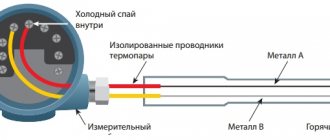
Thermocouple device
The principle of operation of a thermocouple. Seebeck effect
The operation of a thermocouple is due to the occurrence of the thermoelectric effect, discovered by the German physicist Thomas Seebeck in 1821.
The phenomenon is based on the occurrence of electricity in a closed electrical circuit when exposed to a certain ambient temperature. An electric current occurs when there is a temperature difference between two conductors (thermoelectrodes) of different compositions (dissimilar metals or alloys) and is maintained by maintaining the location of their contacts (junctions). The device displays the measured temperature value on the screen of the connected secondary device.
The output voltage and temperature are linearly related. This means that an increase in the measured temperature results in a higher millivolt value at the free ends of the thermocouple.
The junction located at the temperature measurement point is called the “hot” junction, and the place where the wires are connected to the converter is called the “cold” junction.
Cold junction temperature compensation (CJT)
Cold junction compensation (CJC) is compensation introduced in the form of a correction to the final readings when measuring the temperature at the point of connection of the free ends of the thermocouple. This is due to discrepancies between the actual temperature of the cold ends and the calculated readings from the calibration table for the cold junction temperature at 0°C.
CHS is a differential method in which the absolute temperature readings are obtained from the known value of the cold junction temperature (another name is the reference junction).
Thermocouple design
When designing a thermocouple, the influence of such factors as the “aggressiveness” of the external environment, the state of aggregation of the substance, the range of measured temperatures, and others are taken into account.
Thermocouple design features:
1) The junctions of the conductors are connected to each other by twisting or twisting with further electric arc welding (rarely soldering).
IMPORTANT: It is not recommended to use the twisting method due to the rapid loss of properties of the junction.
2) Thermoelectrodes must be electrically insulated along their entire length, except the point of contact.
Tungsten-rhenium type A-1, A-2, A-3
Excellent temperature measurements up to 1800 degrees.
In industry it is used to measure indicators of about 3000 0С. The lower limit is limited to 1300 0C. Can be used in argon, nitrogen, helium, dry hydrogen and vacuum environments. Thermo-EMF at 2500 0C - 34 mV for measuring devices made of alloys VR5/20 and VAR5 / VR20 and 22 mV, for thermocouples made of alloy VR10/20, sensitivity - 7-10 and 4-7 µV/ 0C.
TVR is characterized by mechanical stability even at high temperatures and copes with alternating loads and sudden thermal changes. It is easy to install and practically does not lose its properties when dirty.
Cons: low thermo-EMF production;
during irradiation, unstable thermo-EMF; drop in sensitivity at 2400 0 C or more.
More accurate results for VAR5/VR20 alloys are observed during long-term measurements, which is not so typical for VR5/20 alloys.
In TVR, electrodes are made of alloys VR5 - positive and VR20 - negative; VAR5 – positive and BP20 – negative or BP10 – positive and BP20 – negative electrode.
A slight presence of O2 can damage a tungsten-rhenium thermocouple. In an oxidizing environment they are used only in fast-flowing processes. Under conditions of strong oxidation, it instantly fails.
Sometimes this thermocouple can be used in high temperature furnace operation in conjunction with a graphite heating element.
Ceramics are used as electrode insulators. Beryllium oxide can be used as an insulator when the temperature affecting it does not exceed the melting point. When measuring values less than 1600 0C, the electrodes are protected with pure aluminum or magnesium oxide. The ceramic insulator must be calcined to be able to clean various impurities. In conditions of increased oxidation, covers made of metal and Mo-Re, W-Re alloys with coatings are used. The measuring device with iridium protection can be used briefly in air.
Checking the functionality of the thermocouple
To check the functionality, connect a special measuring device (tester, galvanometer or potentiometer) or measure the output voltage with a millivoltmeter. If the needle or digital indicator oscillates, the thermocouple is serviceable, otherwise the device must be replaced.
Reasons for thermocouple failure:
- Failure to use a protective shielding device;
- Changing the chemical composition of the electrodes;
- Oxidative processes developing at high temperatures;
- Breakdown of the control instrument, etc.
Tungsten-molybdenum
Operates in inert, hydrogen and vacuum environments.
Measurement temperatures – 1400 0С -1800 0С, operating limits – 2400 0С. Sensitivity - 6.5 µV/0C. Has high mechanical strength. Does not require chemical purity. Cons: low thermal emf; polarity inversion, increased brittleness at elevated temperatures.
Recommended for use in hydrogen, inert gas and vacuum environments. Oxidation in air occurs at 400 degrees. As the thermal feed increases, oxidation accelerates. TBM does not react with H and inert gas up to melting temperatures. It is better not to use this type of thermocouple without insulators, since it can react with oxides when the temperature rises. If there is a ceramic insulator, short-term use in an oxidizing environment is possible.
To measure the thermal component of the liquid metal, it is usually isolated with alumina ceramics using a quartz tip.
Advantages and disadvantages of resistance thermometers
Like any device, the use of resistance thermometers has a number of advantages and disadvantages. Let's look at them.
Advantages:
- almost linear characteristic;
- measurements are quite accurate (error no more than 1°C);
- some models are cheap and easy to use;
- interchangeability of devices;
- work stability.
Flaws:
- small measurement range;
- quite low limiting temperature of measurements;
- the need to use special connection circuits for increased accuracy, which increases the cost of implementation.
A resistance thermometer is a common device in almost all industries. This device is convenient for measuring low temperatures without fear for the accuracy of the data obtained. The thermometer is not particularly durable, however, the reasonable price and ease of replacing the sensor make up for this minor drawback.
Platinum-rhodium-platinum types R, S
The most common types of thermocouples for temperatures up to 1600 0C.
These devices include platinum with an alloy of platinum and rhodium of 10% or 13% composition. Used in inert and oxidizing environments. Long-term use at 1400C, short-term use at 1600C. They have a linear thermoelectric property in the range of 600-1600 0C. The sensitivity indicator is 10-12 µV/0С (10% Rh) and 11-14 µV/С (13% Rh). They produce high-precision measurements, have high reproducibility and stability of thermo-EMF. Disadvantages: instability in the irradiated environment, increased sensitivity to contamination.
TPP with a good insulator can be used in reducing environments, and in conditions containing arsenic vapor, sulfur, lead, zinc and phosphorus.
They are practically not used for measuring negative temperatures due to reduced sensitivity. But, in a separate assembly it is possible to measure values up to -50 degrees. For values of 300-600 0C they are used as comparative indicators. Short-term use – up to 1600 0С, long-term use – 1400 0С. With protection, it can be used for a long time at 1500 0C.
Quartz and porcelain materials or mullite and sillimanite are used as insulators at temperatures up to 1200 0C. Reference thermocouples are insulated with fused quartz.
When used with a generated temperature of 1400 0C, it is better to use ceramics with Al2O3 oxide as an insulator. In a weakly oxidizing and reducing environment, about 1200 0C.
In weakly oxidizing and reducing conditions with temperatures above 1200 and regardless of conditions with temperatures above 1400 0C, it is necessary to use ceramic high-purity aluminum oxide as an insulator. In a reducing environment, magnesium oxide can be used.
Typically, the inner casing for a thermocouple consists of the same material from which the insulator is made. These materials must be gas-tight. In conditions of one-time temperature measurement of liquid steel, quartz tips are used to protect the working junction of the meter.
The entire working length of the electrodes must be insulated with a two-channel ceramic tube. The junction of the tube and the cover, the electrode and the tube must have gaps for ventilation. Electrodes must be thoroughly cleaned of grease before installation in the insulator. In turn, the metal case must also be dry and clean. All thermocouple components must be annealed before installation on site. Thermoelectrodes should not perform a supporting function for the insulator. This is especially important for vertical thermocouples.
RESULTS
ROOM ÑеÑмоÑлекÑиÑеÑкий пÑеобÑÐ°Ð·Ð¾Ð²Ð°ÑµÐ»Ñ — не иÑклÑÑение. RESULTS ¾ÑÐ½Ð¸Ñ Ð´Ð°ÑÑика, коим ÑвÐ"ÑеÑÑÑ ÐµÐ³Ð¾ “гоÑÑÑийÂ" к онеÑ. RESULTS RESULTS. RESULTS ±Ð¾ÑаÑÑ Ð½ÐµÐ¾Ð±Ñодимое напÑÑжение, в ÑезÑÐ »ÑÑаÑе Ñего плиÑа полноÑÑÑÑ Ð½Ðµ ÑÑнкÑиониÑÑе Ñ Ð»Ð¸Ð±Ð¾ ÑабоÑÐ°ÐµÑ Ñ Ñ Ð¿ÐµÑебоÑми.
Is it OK? RESULTS ROOM ее â Ð¿Ð»Ð°Ð¼Ñ Ð³Ð°ÑнеÑ. RESULTS RESULTS °Ñной бÑмагой Ñ Ð¼ÐµÐ»ÐºÐ¸Ð¼ зеÑном. RESULTS RESULTS ROOM мопаÑÑÑ.
Platinorhodium-platinumrhodium type B
Used in oxidizing and neutral conditions.
Operation in a vacuum environment is possible. The maximum measurement temperature for long-term flow is 1600 0C, short-term - 1800C. Sensitivity - 10.5-11.5 µV/0C. It is distinguished by good stability of thermal EMF. It can be used without extension wires due to low sensitivity in the temperature range from 0 to 100 0C. Made from an alloy of platinum and rhodium PR30 and PR6.
In a reducing atmosphere and vapors of metallic and non-metallic composition, reliable protection is necessary. Ceramic raw materials made of pure Al2O3 are used as an insulator.
The operating characteristics and strength data correspond to thermocouples of types R, S. However, they fail much less frequently due to their low susceptibility to chemical contamination and grain growth.
Mode of production
Chromel and alumel are among the most labor-intensive to produce. The complexity of the technological process lies in the need for strict control of the proportions of components during melting, since the key characteristics of the final product are determined mainly by the ratio of materials. The compositions are produced in induction furnaces of various frequencies.
The melting order is as follows. Most of the chrome is loaded into a liquid bath, leaving a few kilos for correction. Then nickel and flux are introduced at the same time. Melting is carried out in intensive mode. Metal deoxidation is carried out by adding manganese and magnesium. Then the thermoelectromotive force is determined and the chromium content is adjusted.
Other nickel alloys are produced in a similar way. The differences lie in the order of loading materials and oxidizing agents. For example, the production of alumel alloy is carried out as follows. Nickel and flux are loaded, followed by the remaining components. Magnesium is used as an oxidizing agent. This is how alumel alloys, chromel and copel are obtained.