Electrical network repair is work related to electricity. There is always a danger of injury to an employee by electric current of various voltages. How do you know if current is flowing through a wire or cable? A voltage indicator (VI) will help determine which wire is energized. Disabling the area under the potential difference does not mean that it is absent on the current-carrying parts. Only with the help of such devices can you be sure that it is not there.
Voltage indicator
Device and principle of operation
The main structural elements included in any indicator are:
- one or two metal tips, the tip of which directly touches the exposed live part to determine the presence or absence of voltage;
- light, sound or digital indicator that gives a signal in the presence of electricity;
- a housing made of insulating material that contains a neon light bulb, an LED or an LED matrix, and may also contain an electronic board and a quenching resistor.
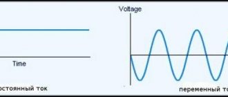
The operating principle and design of the indicators depend on what kind of current will flow: active or capacitive. The first type of UN involves working with both alternating and direct currents up to 1000 V. The second is designed to work only with alternating currents.
Attention! An incandescent lamp with leads attached to it to monitor the voltage on the wires is not an indicator. Its use is strictly prohibited.
Structurally, indicators can have two housings with tips connected to each other by a conductor. In this case, the length of such a conductor should not be more than 1 m; the places where it enters the housings (handles) are framed with thickening and have shock-absorbing inserts.
Double pole indicators
The principle of operation of indicators of this type is based on comparing the potentials in 2 current-carrying parts of the equipment being tested: zero and phase. Unlike single-pole indicators, these devices are equipped with two probes. A person does not come into contact with the controlled voltage and is separated from its influence by a layer of insulation. The indicator includes a signal lamp and 2 resistors: a shunt and a current-limiting one. The connection between the probes is made with a rubberized flexible wire.
You may be interested in this Characteristics and connection diagram of the SO-505 electric meter
Of the old models of bipolar voltage indicators up to 1000 V, MIN 1 and UNN-10 with an operating potential range of 70–660 volts are still used. The signal lamp of these devices lights up at 60–65 V. Using the indicated products, the circuit is checked for integrity. Simple versions include indicators of the PIN-90, UN-500, UNNU-1 series - they only detect the presence of voltage. More advanced models ELIN-1, IPM also indicate the potential value and polarity.
LEDs of all colors, neon bulbs and digital indicators are used as a signal. There are also combined indicators - sound is added to the glow, which increases the safety of handling the device. The most famous digital two-pole voltage indicator is the multimeter. It is able to determine the magnitude of AC and DC potential, strength and frequency. The device is often used to solve everyday problems.
Types of indicators for determining voltage
The conductive parts of the installations with which electrical personnel have to work are divided according to the value of the supply voltage. A distinction is made between circuits with voltages up to 1000 V and over 1000 V. Due to the fact that the use of a voltage indicator involves touching a bare wire with its working electrode, indicators are divided into voltage indicators up to 1000 V and those designed for voltages above 1000 V.
Checking the voltage at the outlet
In addition, UN are divided according to the following characteristics:
- number of poles (with one or two contact electrodes);
- type of current (direct or alternating);
- type of indicator (neon, LED, digital, acoustic).
In the line of modern indicators, there are samples with non-contact testing for the presence of high voltage. UN makes it possible to check the presence of Uphase (Uph) on high-voltage lines (HVL) and current bus assemblies of closed (closed switchgear) and open (ORU) switchgears with Uph from 1 kV and higher.
Information. A non-contact UN produces an intermittent optical or acoustic signal when its testing part approaches an element located under Uph. Its own power supply allows not only to issue indication signals, but also to monitor the serviceability of the UN.
Single pole pointer
Low voltage indicators (LVL) with one pole have a neon light bulb located in the housing. It has an ignition threshold of up to 90 V and a series-connected resistance, one end of which is connected to the contact pad on the indicator body. To determine the presence of Uph, you need to touch the bare wire with the tip of the pointer, and with your finger - the contact pad on the body. As a result, the capacitive circuit is closed through the human body to the ground. When there is voltage, the indicator lights up.
Single-pole indicators can be made in the form of a screwdriver with a transparent body, inside of which a light bulb glows. Examples of such probes are INO-70, UNN-90 and others.
Carefully. Single-pole indicators are designed to test the absence or presence of AC voltage only. Before use, it is necessary to know the value of the maximum permissible potential difference. This information is printed on the device body.
Single-pole indicator in the form of a screwdriver Vira 100-500V 390220
Two-pole voltage indicator
Pin 90 voltage indicators refer to voltage indicators that have two poles connected to a section that conducts electric current. Pin 90, as a model representing such testers, allows you to work in the range of values from 50 V to 1000 V. They can determine the presence of a “phase” by the glow of the lamp, touching one electrode to the test area, the other to the neutral or grounding conductor. In the absence of such, the presence of phase voltage can be determined by touching one contact tip to the “phase”, and the other by touching with a finger. In three-phase AC networks, you can check both phase (220 V) and line voltage (380 V).
Important! Before working with the UN, it is necessary to visually inspect the housings for the absence of mechanical damage, and the flexible conductor for the integrity of the insulation. Before work, you need to make sure that the indicator is working properly by touching an area that is known to be energized.
Double-pole indicator Pin 90M
High voltage indicators (HVN) over 1 kV
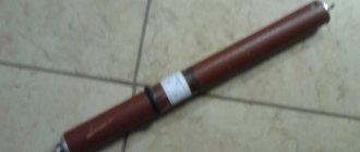
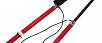
On 6-10 kV power lines, a voltage indicator UVN 10 is used. This device allows you to monitor Uph, both on overhead lines and in ground-based high-voltage installations. It belongs to the group of basic protective equipment for working in power plants, since with its help you have to touch live parts of installations.
The device includes: a working part, an insulating section and a handle. In the working part there is an electrical circuit that converts the electrical signal into light and sound form. The circuit is located in the area of the shader (reflector), which is designed to enhance optical and acoustic indications. This is achieved through its directed action.
Basic requirements for the design of UVN:
- indication signals must have a continuous or intermittent operating mode and be clearly recognizable;
- the insulating part must be located strictly between the handle and the working part;
- if the insulating part consists of several links (collapsible) or telescopic, then the fastening between the links should ensure the strength of the entire structure, sliding fixation against spontaneous movement;
- the pointer must have a mass that allows one person to operate it;
- The rubber or plastic cover of the shade must contain a mirror reflector.
Such indicators must have a design that allows testing the voltage on a 6 kV or 10 kV overhead line without grounding their working parts.
UVN-10 appearance
Universal pointers
The instruction diagram of such devices describes them as a portable tester that allows for sound and light indication during testing. It is used to determine:
- phase;
- zero;
- absence or presence of voltage (from 12 to 500 V DC and up to 380 V AC).
With the help of such UN, you can perform a “continuity test” of the circuit integrity and find out the order of alternation or coincidence of phases. The power source in the universal probe is a capacitor with a large capacitance value. It can be equipped with a line of LEDs or a liquid crystal display.
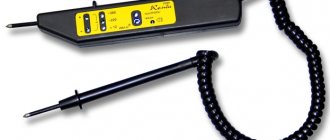
One of the representatives of universal UN models is “contact 55 em”. It has the following parameters:
- operating voltage range – 24-380 V DC or AC;
- electrical insulation strength – 1 kV;
- current through the pointer at 380 V – up to 10 mA;
- Rmax of the external circuit during continuity is not less than 500 kOhm.
Such a device can operate without recharging for 24 hours, charging time is no more than 30 seconds.
Universal UN Contact 55 EM external device
The presence or absence of voltage is monitored by light and sound indication. The ability to mount a second probe on the body of the first allows you to easily test the power outage at the outlet.
Contact 55EM in action
Description of single-pole devices
An indicator screwdriver is a simple and popular tool among home craftsmen. It also resembles a school pen made of transparent dielectric, equipped with additional resistance and a neon light bulb. The detectable voltage is 100–500 V with an alternating current frequency in the network of 50 Hz. The scope of application of the device is checking secondary circuits, cartridge phases, sockets and switches. The tip of the pointer is pressed against the conductor being tested, and the other contact of the indicator is closed by touching the finger, organizing an electrical circuit:
- phase potential;
- element being checked;
- internal circuit of the device to the terminal pad;
- hand and other parts of the human body;
- Earth.
The strength of the flowing current is safe and does not exceed 0.3 mA, but it is enough to glow neon. Indicators of this type have many names: IN-91, INO-70, UNN-90, UNN-1M. The range of potentials determined by the UN-453M device is from 24 to 1200 V.
Design and method of application
The product instructions describe the design features and operating rules. Standard recommendations may have some discrepancy with individual developments. However, the basic requirements are met for all models:
- ferrule;
- dielectric housing;
- display device.
Voltage tester
When working, it is necessary to touch the area under test, taking into account what voltage may be there and whether it falls within the operating range of the indicator.
Important! If there is no assumption at what voltage the de-energized section may be under, the lack of potential is checked first by the UVN, then by the UNN.
Use of control devices
Before each use, the indicator is inspected for damage to the housing or insulation, after which the functionality of the indicator is checked by touching a phase that is known to be energized. A defective device will cause an error resulting in a short circuit or personal injury. When taking measurements, you must be careful and follow the basic rules:
- the indicator must correspond to the network parameters - it would be useful to verify this by looking at the markings on the device body;
- during the check, take a stable position, excluding unexpected falls and contact with grounded conductors;
- One way to avoid unwanted contact is to keep your free hand in your pocket so you don't accidentally create a closed circuit for electrical charge.
When working with a single-pole indicator, it is prohibited to use dielectric gloves: contact of the plate on the indicator handle with the operator’s finger must be ensured. We must remember that electricity is dangerous - not only beginners, but also experienced installers die from mistakes.
You might be interested in this Symbol of radio components on the diagram and their name
High voltage device (more than 1 kV)
Such devices can be either single-pole or double-pole: UVN - 10, UVN - 80 and similar models. For example, you can consider a high voltage indicator UVN 10.
With its help, the phasing of power transformers in power plants and cables designed to operate on alternating current with a frequency of f = 50 - 60 Hz and U = 6 - 10 kV is carried out.
There are several versions of this device, which have:
- pulse light indication with self-control (UVNU -10 SZ);
- the same parameters plus a power source (UVNU - 10 SZ IP);
- phase indicator, light-pulse indication plus phasing tube, no IP (UVNU - 30 SZ TF);
- the same parameters as the previous model, plus IP (UVNU - 10 SZ IP TF);
- UN with IP contact-non-contact (UVNU – 10 SZ IP KB);
- phase indication, power supply, phasing tube, two-pole (UVNU – 10 SZ IP KB TF).
Despite the abundance of indicators designed for different voltages and types of current, they all must undergo periodic testing in special laboratories.
Routine checks and tests of pointing devices
Regardless of the activity of use, all UVNs, without exception, must undergo periodic laboratory electrical tests once a year. Basically, such procedures concern the dielectric properties of the insulating part and the voltage at which the indicator is triggered.
Devices with visible damage to the integrity or cracks of the dielectric section are considered unsuitable for use.
Further verification is carried out as follows:
2. A HV transformer is connected to the freed threaded bushing and to the electrode pre-attached to the handle.
3. Apply a test voltage significantly higher than the rated voltage for 5 minutes.
The main condition when working with any electrical and current-indicating instrument or device is strict adherence to safety rules.
Expert opinion
It-Technology, Electrical power and electronics specialist
Ask questions to the “Specialist for modernization of energy generation systems”
Voltage indicator: classification, how to choose and test methods Testing with increased voltage consists of applying a voltage exceeding at least 10 from the working one between the tips for bipolar ones, and between the tip and the side or end contact for a single-pole indicator, for 60 seconds. Ask, I'm in touch!
Pointer tests
Laboratory tests are carried out by organizations that have a special license for this. To carry out the test, a circuit is assembled, which includes a high or low voltage indicator.
The UNN is tested for the insulation condition and the indication voltage value. They also check its operation at increased voltage, while measuring the current. The voltage, gradually increased from zero, is brought to exceed the operating voltage by 10% and is maintained for 1 minute.
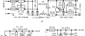
Electrical installation diagram for testing the insulation of the housing and wires of the ULV up to 1000 V
The UVN is tested starting from the working part, applying voltage to the tip and screw connection. If the indicator voltage is higher than 35 kV, the working part is not checked, only the condition of the insulating part and the handle is tested.
Scheme of the testing facility for UVN
The results obtained are documented in a protocol and entered into a journal. A product approved for use is equipped with a tag with a stamp indicating the date of the next verification.
Voltage gauges and indicators are used to ensure the safety of operating personnel during work; they can also be fraught with danger. Storage, correct use and daily visual inspection must be ensured by those directly using the indicator. It is prohibited to use the device if the inspection period has expired, or if it has been subjected to mechanical damage as a result of a fall or impact.
Thermal power engineer's blog | Voltage indicator: types, functions, application
- The handle and the insulating part of the device are connected;
- An external inspection checks the integrity of the insulating part for the presence of delaminations, cracks and other mechanical damage.
- Dielectric gloves, tested and verified by external inspection, are worn. Using the device without gloves is prohibited;
- The serviceability of UVN 10 is checked by approaching parts of electrical equipment where voltage is present. Sometimes a special portable device is used for testing;
Voltage indicator - operating principle and application features (100 photos)
UVN tests from 1000 V
The main purpose of the indicators is to determine the presence or absence of voltage, including phasing, on the current-carrying elements of ground distribution installations and overhead lines. This device should be used strictly while wearing dielectric gloves.
- working part with a built-in gas-discharge or LED lamp, as well as acoustic indication;
- an insulating part, which is located between the working part and the handle;
- from a handle with a restrictive ring. Can be part of the insulation or a separate element.
Periodic tests of UVN, as well as UNN, must be carried out at least once a year. According to Order of the Ministry of Energy of the Russian Federation dated June 30, 2003 N 261, Appendix 7.
The method of electrical testing of indicators from 1000 V consists of supplying high voltage current, separately to the working and insulating parts of the UVN. Also, the device indication voltage must be determined.
You can check the UVN in Moscow in our electrical laboratory or write to The email address is being protected from spambots. Javascript must be enabled in your browser to view the address.
- working part with a built-in gas-discharge or LED lamp, as well as acoustic indication;
- an insulating part, which is located between the working part and the handle;
- from a handle with a restrictive ring. Can be part of the insulation or a separate element.
For UVN and UNN tests that have passed, a stamp is placed indicating the operating voltage of the device and the date of the next test.
Electrical laboratory stamp confirming successful testing of personal protective equipment, the use of which depends on the voltage of the electrical installation
Expert opinion
It-Technology, Electrical power and electronics specialist
Ask questions to the “Specialist for modernization of energy generation systems”
Single-pole To monitor the voltage from a constant source, the Contact 55EM voltage indicator in the same row of LEDs has another one with the designation -, which allows you to determine the positive and negative wires. Ask, I'm in touch!