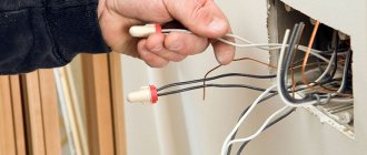
Surely many have found themselves in a situation where, when the wire at the plug is moved, various noises appear in the headphones, or when the sound in one of the headphones disappears and appears briefly, and then disappears again, and how this unpleasant situation ultimately drives them crazy. Inadvertently the cord was pulled several times, accidentally bent, stretched - all this leads to a partial or complete break of the conductors inside. Or when the microphone on the telephone headset with the buttons on the remote control fails. There are even more comical situations when the tip of the plug falls off. This mini-review will roughly consist of two parts. In the first part I will show how I used to repair damaged headphone plugs on a collective farm. But one way or another, I’m tired of this method. Therefore, the second part will be devoted to these purchased dismountable plugs.
Types of connectors
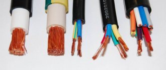
Connectors that provide connections to electrical circuits come in different types, much depending on their size:
- Micro-jack 2.5 mm is used in miniature devices: smartphones, tablets, etc.
- Mini-jack 3.5 mm are designed for a wide variety of household appliances, including desktops and TV receivers.
- Big-jack 6.35 mm is a connector that is necessary for acoustic devices: amplifiers, guitars, mixers, etc.
Each of them has several subspecies depending on the number of outputs:
- With two contacts, asymmetrical pulses are transmitted. Example: mono impulses for headphones, recording on a microphone.
- If there are 3 contacts, then it is permissible to transmit symmetrical and asymmetrical pulses. Connections No. 2 and No. 3 are fixed to each other using an additional adapter.
- The 4-pin jack allows you to broadcast video and audio impulses in one package. The elements are used in smartphones, tablets, and audio devices.
- The 5-position unit is an outdated format, it was developed by Sony for the Xperia Z series phones. In this case, 2 microphones function, 1 controls noise reduction. The sockets also have 2 types: standard, created for special blocks, and switchable (can be adjusted to any connection).
If the block has 3 outputs, it is called TRS. The cable includes 3 cores.
There are combinations - 2 pairs, one wire from a pair of one color is taken as a common one, and connected together.
Standard
In the simplest wiring, the right channel is attached to the middle ring, the left - to the connecting block. The cores are fixed in the appropriate places intended for soldering - they are easy to detect upon closer inspection or check with a tester.
Product 2.5 is made on the same principle as 3.5, the only differences are in size. The wiring on both types is the same. In mobile phones, headphones and microphones are fixed using mini- and micro-USB connectors. They can be used while listening to MP3 files.
Non-standard
There are devices where the input to the headset is different. For example, in phones from various companies:
- Nokia;
- Samsung;
- Ericsson.
In headsets with a button, a USB connector is sometimes installed; when repairing such devices, difficulties arise due to the non-standard plug. Then you need to connect a standard headset through the appropriate adapter.
Checking the headphone pinout of non-standard connectors
In some mobile devices and GSM phones, in most cases, from previous years of production, phones with original special connectors were used. In such cases, using search engines you can find the original pinout of the headphone connectors. It may have different connection diagrams, for example, shown in the figure.
If the headphones of such devices fail, you can cut the headphone cable, purchase a new headset, and install new headphones in accordance with the diagram.
If there is no information on the Internet, you can independently determine the pinout of the headphones. To do this you need to do the following:
- disassemble the housings of the dynamic headphone system; for this you can use an active solvent;
- ring the terminals of the headphone speakers, zero resistance will correspond to the common wire;
- ring the contacts of the connector with the common wire, the contact number at which the multimeter shows a resistance close to zero will be the contact for connecting the common wire;
- similarly, you should make a call to the opposite contacts of the headphone speakers;
- for a headset with a microphone, search for connections to the connector contacts for each output separately.
Pinout diagrams for headset with microphone
The pinout varies, much depends on the headphones. Blocks have from 2 to 4 elements, each part transmits its own signal. For example, the connection block has 2 elements; it is equipped with one wire, which is intended for a microphone.
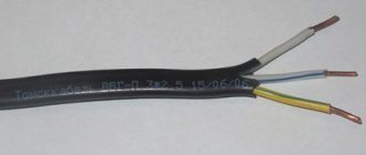
If there are 3 elements, then there are 3 wires:
- right;
- left;
- general.
In the headset, the 1st channel is connected to the right earphone, the 2nd channel to the left, the common one supervises the fixation of contacts.
A cable is pulled to the plug; in the center it is divided into 2 wires, each going to its own earphone. The block has 4 elements. In this combination, it is differentiated into 2 types. The 1st block consists of 4 wires (most often this happens in phones, tablets, players). The channels are divided into left, right, general and microphone.
All modern modifications of phones are equipped with plugs in which there are 4 elements (fixed with headphones and a microphone).
The pinout is done according to the same scheme for the following devices:
- "Apple";
- "Samsung";
- "Lenovo".
If you analyze the connecting block, it is composed of several elements. Each of them supplies impulse to its own channel.
How does a headphone plug work?
If the cable is frayed, torn or the plug (pin) comes off, the device is repaired using a soldering iron with consumables and a new connector (if that is the problem).
Headphones 3.5mm
Since the 3.5 mm connectors are non-separable, for repairs you will have to buy a dismountable one, crimp the cable with a special clamp, solder the contacts according to the diagram shown below and assemble the connector.
3.5 mm plug structure
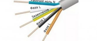
Manufacturers adhere to standards in insulation painting:
- red – left speaker – first contact or tip;
- green – right channel or ring;
- blue – speaker;
- colorless or copper-colored - mass;
- a different color – leads to the control panel (buttons).
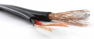
In more expensive models, each channel may have its own mass: red-copper is the mass for the left channel, and green-copper is for the right. The microphone cable is sometimes shielded with a braided cable and varnished.
The coloring of the insulation is often violated, so relying on the coloring is wrong. To determine which pin corresponds to which channel, put on headphones and ring all combinations of wires one by one until the speaker starts to make noise. This way you can determine the mass and both channels.
The resistance between the headphones is twice as high as between ground and the audio channel.
Headphone circuit with microphone
For a headset, the schematic drawing looks different, because it is designed differently - equipped with an additional cable for transmitting sound from a microphone.
Have you noticed that in the diagrams there are different contacts for ground and microphone? Nothing strange. There are a couple of TRRS types (specifications) available with different ground and microphone contact locations. In CTIA (computer standard), the second ring (third contact) is connected to the common contact, and the sleeve is connected to the microphone, in the case of OMTP (telephone specification) it is the other way around: the 3rd contact is the speaker, the 4th is ground.
The standards are relevant only for headsets - headphones with a microphone; they have no relation to devices without one.
The standards are relevant only for headsets - headphones with a microphone; they have no relation to devices without one.
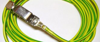
Figure No. 1
We noticed that some headsets with iPhone work adequately. The microphone fails, the volume control and track switching do not function due to the fact that most accessories are produced with the international OMPT pinout, and Apple uses the American circuit - CTIA. The problem is solved by purchasing a CTIA - OMPT adapter (see Figure No. 1) or by resoldering the 3rd and 4th contacts (they are swapped) in the headset.
The headphone pinout will allow you to correctly solder the pins when repairing the device, for example, replacing a damaged plug or cable. It depends on the number of contacts and the specification used: CTIA or OMPT.
Headphone wiring
For standard headphones to work, 3 wires are needed, counting from the sharp end to the cable. Some models have 4 elements, divided into pairs. Wires of the same colors are soldered together. Removing them with a jack connection is easy. The elements are attached to the intended places, which are found using a tester. Jack 2.5 differs only at the connector point, but the algorithm is the same. Micro and mini-USB are available in mobile devices; they are fixed congruently.
Necessary equipment
Tools required for desoldering:
- medium power soldering iron (up to 25 W);
- solder;
- rosin;
- multimeter;
- pliers;
- blade;
- manicure scissors;
- sharp knife;
- small screwdriver;
- emery cloth.
At the beginning of work, the connector is tested; it must match the one that is being dismantled.
How to ring wires
Wires going to various parts of the device are ringed using a tester. First of all, we are looking for those that go to the speakers:
- We clean the ends. In some types of models, the wire that goes to the microphone is shielded, and the screen is capable of performing the functions of the corresponding cable.
- We put on headphones. After connecting the tester, we will hear a crackling sound from the speakers. If sound comes from only one, the tester is not connected correctly. It probably only contacts the speaker where the sound is coming from. It is necessary to connect the tester to the common wire. If sound is coming from both headphones, the tester is contacting both channels.
Our actions will differ depending on the number of wires:
- If there are 4 wires in the cable, the one that remains should be connected to the microphone and volume control through the control panel.
- If there are five, there are two left that need to be checked. If they can communicate with each other, but cannot communicate with the speakers, they need to be connected to a microphone. And if others call, we solder them to the terminal together.
- If there are seven wires, the rest are connected in pairs to the microphone with the headset button. They are soldered depending on the colors, both to the microphone and to the common terminal.
Why do headphones break?
The main reason is “factory settings”. Each model is designed for a specific service life. Good headphones are not the ones that don't break, they are the ones that people buy all the time. Therefore, if your favorite couple breaks down, don't blame yourself. These are all the tricks of greedy manufacturers and monster engineers who profit from unhappy customers.
Expensive headphones last longer, but they also break. Their price is determined not only by quality. Premium technology costs what consumers are willing to pay for it.
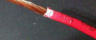
Remove the cable braid
It is most convenient to cut the braid exactly as in the photo. You don't need to press the blade too hard. Thanks to bending, the braid will diverge on its own, regardless of its shape. We turn the wire, making cuts and, when we have gone through the circle, we tighten the braid. The main thing is not to cut through the wiring.
The wiring is varnished and needs to be cleaned off. You can do this with a knife. But if your knife, like mine, is dull, then the result will not be very pleasing.
The wires are very thin and the dullness of the knife leads to them being torn off along with the varnish. In principle, this can be done quite easily with a sharp knife. But we don’t have a sharp knife, so we’ll use a lighter or any other source of fire.
General recommendations
TRS type connectors have a standard pinout. Poor audibility in the headphones may be the result of a break in the common wire or a mismatch between the output impedance of the mobile device amplifier and the impedance of the dynamic headphone system.
TRRS connectors have two types of pinout: CTIA and OMTP. Installing headphones with non-native pinouts leads to distortion of the sound signal and can lead to a malfunction of the microphone.
Topic materials: How to connect wireless headphones to your phone
How to properly set up a headphone microphone on a Windows computer
How to properly warm up your headphones and whether you need to do it
How to fix headphones yourself if one stops working
How to improve sound quality in headphones
, The earphone does not work: fault diagnosis, repair methods
, No sound in headphones
, DIY headphone repair
, Making your own simple headphones and headsets with a microphone
The headset jack differs from the headphone jack in that it has an additional fourth contact, so things are a little more interesting with them. And the reason for this is the presence of a microphone, which elevates the headphones to the rank of a headset. Usually the main problem when trying to repair a headset jack is determining which wire should be soldered where. This is understandable, most often the problem is that there are 4 contacts on the connector and 5 wires. And even if there are 4, then who goes where...?
The entire headphone repair process is shown in detail in my new video:
Repairing the headphone jack has already been discussed in one of the articles.
General recommendations
TRS type connectors have a standard pinout. Poor audibility in the headphones may be the result of a break in the common wire or a mismatch between the output impedance of the mobile device amplifier and the impedance of the dynamic headphone system.
TRRS connectors have two types of pinout: CTIA and OMTP. Installing headphones with non-native pinouts leads to distortion of the sound signal and can lead to a malfunction of the microphone.
Topic materials: How to connect wireless headphones to your phone, How to properly set up the headphone microphone on a Windows computer, How to properly warm up the headphones and whether you need to do this, How to fix the headphones yourself if one stops working, How to improve the sound quality in the headphones, The headphone is not working : fault diagnosis, repair methods, No sound in headphones, Do-it-yourself headphone repair, Self-production of simple headphones and a headset with a microphone
What does the sound in headphones consist of?
Many cores are channels, each of which outputs the content of a specific frequency band to the master bus in the speaker (the one that is inserted into the ear). Thus, it is clear that damage to at least one of these veins completely eliminates the frequency range for which it is responsible. Why can't you hear this?
It's about two things:
- stereo;
- the rest of the veins.
If one frequency is missing on the left, it will be heard on the right. In addition, when the frequency at which the channel was output loses it, the residual signal is transmitted through other wires. Thus, the overall load on the sound increases. It starts clipping and overloading. Why do cheap headphones for 30 rubles sound so bad? The number of people living there is minimal and they don’t listen to modern music at all. What can I say, even radio broadcasts are difficult to broadcast.
As for grounding, everything is simpler there. As long as at least one core is functioning, it exists. But as soon as she rubs it, the sound will change.
It is this factor that is the reason that the contacts are tinned and not exposed using a stationery knife.
A good example of frequency loss is an audio splitter. A device that divides one headphone input into two. Not only the volume sags, but also the frequency range. The sound stops pumping, it becomes quiet and flat, and the dynamics disappear. All for the same reason. The number of cores remained the same, but the number of outputs doubled.
How to find out if the connector is faulty
Insert working headphones into the jack and turn on the music. If music does not play in working headphones, your connector is broken. Also, if you hear a hissing sound when the plug moves, this means that the connector will soon fail completely.
Nowadays, the pinout of headphone wires with a microphone shown in the first picture below is mostly used everywhere, but there is also another one, which is mainly used on old phones and in phones from some manufacturers. They differ in that the microphone and ground contacts are swapped.
Self-replacement of the 3.5 plug
We will need a knife, soldering iron, solder, rosin. Cut off 5-10 cm of wire from the plug, remove all the insulation from the plug, remember the sequence of wires by color (sometimes they are different). Strip the wires and solder them to the 3.5 mm jack. It is better to fill the soldering area with hot glue and compress it with heat shrink, so the connection will last much longer. Read more about the renovation here
Electrical methods for determining headset wiring
Unfortunately, it’s not always possible to easily open the control panel and earphone just like that. In such cases, you should use a multimeter.
We set the mode as in the picture and poke one probe into the yellow wire, the second probe into the rest. The vast majority of headphones have an impedance of either 16 or 32 ohms. These are standards. In practice, exactly 16 or 32 is rare, usually within +- 3 Ohms, but there are also 10, 24, and 54 Ohms.
The main thing is that the speakers have the same resistance among themselves. So let's say the speakers have a resistance of 32 ohms each. If we grab the ground and one of the channels with the probes of the multimeter, it will show us 32 Ohms. But if one probe is for one channel, and the second for another channel, then it will show the total resistance (in our case 64 ohms), i.e. The speakers in this case are connected in series. If you could not find both speakers, then the wire is broken somewhere further.
Don't have a multimeter? No problem