Types of solid state relays
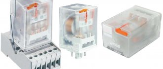
TTPs can look different. Below in the photo are low-current relays
Such relays are used in printed circuit boards and are designed for switching (switching) low current and voltage.
Ready-made input-output modules, which are used in industrial automation, are also built on the TTR.
And this is what relays used in power electronics look like, that is, in electronics that switch large currents. Such relays are used in industry in control units of CNC machines and other industrial installations
On the left is a single-phase relay, on the right is a three-phase.
If a decent amount of current flows through the switched contacts of the power relays, the relay body will become very hot. Therefore, to prevent relays from overheating and failing, they are placed on radiators, which dissipate heat into the surrounding space.
Solid State Relays by Switching Type
With zero crossing switching
Look closely at the diagram
Such SSRs switch alternating current at the output. As you can see here, when we apply a constant voltage to the input of such a relay, switching at the output does not occur immediately, but only when the alternating current reaches zero. Shutdown occurs in a similar way.
Why is this being done? In order to reduce the influence of interference on the loads and reduce the pulse current surge, which can lead to load failure, especially if the load is a circuit based on semiconductor radio elements.
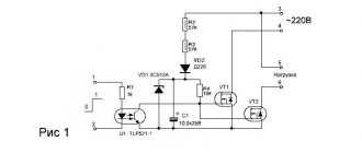
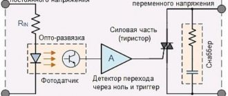
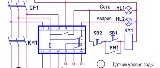
The connection diagram and internal structure of such a SSR looks something like this:
DC control
AC control
Instant on
Everything is much simpler here. Such a relay immediately begins to switch the load when control voltage appears on it. The diagram shows that the output voltage appeared immediately as soon as we applied the control voltage to the input. When we already remove the control voltage, the relay turns off in the same way as the SSR with zero crossing control.
What is the disadvantage of this TTP? When a control voltage is applied to the input, current surges may occur at the output, and as a result, electromagnetic interference. Therefore, this type of relay is not recommended for use in radio-electronic devices where there are data transmission buses, since in this case interference can significantly interfere with the transmission of information signals.
The internal structure of the SSR and the load connection diagram look something like this:
With phase control
Everything is much simpler here. By changing the resistance value, we thereby change the power at the load.
An approximate connection diagram looks like this:
Solid state relay
Due to its high performance properties, solid-state relays are gradually replacing power electromagnetic devices and contactors. The device is widely used in areas such as industrial automation, chemical, medical, mining, military electronics and many other areas.
The concept “solid-state” carries information about the absence of moving components. The use of an electronic power switch in the design allows the device not to create an arc during operation. This quality makes it possible to use the described relay in chemical plants, as well as in rooms with heavy gas and dust contamination. In addition, the device has an instant response to a signal and operates silently over a wide range of temperatures.
The different needs of automatic circuits determine some design features. Solid state relays differ in the number of phases:
- Single phase solid state relay . solid state relay is controlled using an analog signal.
- Three phase solid state relay . Its operating principle creates reliable regulation of several circuits at the same time.
Based on the operating current parameters, solid-state relays are distinguished between DC and AC solid-state relays.
The long service life of the device is ensured by the absence of arcs and sparks. The price of a solid-state relay is higher compared to other types of devices, but its use is economically beneficial. Turning on the device requires less electrical energy, and the workflow is controlled using microcircuits.
Advantages and disadvantages of solid state relays
Solid-state devices have a number of advantages, namely:
- silent process:
- huge working resource;
- ultra-fast response to signals;
- electrical energy consumption is 95% lower than that of electromagnetic type devices.
Of course, the device has high performance qualities, but it also has a number of disadvantages. Relays of this type heat up while performing their functions. Various overloads and short circuits can disable the power switch. Using an automatic key in this case does not save you from damage if a short circuit occurs. In addition, pulsed power surges can instantly break the device. It is worth noting that a solid-state relay has leakage current, which means, for example, an LED lamp controlled by a circuit with a solid-state relay will blink.
Despite some shortcomings and features, the described device is becoming more and more popular every day and is displacing other types of relays from many industrial areas. In order to choose the right solid-state relay, you need to familiarize yourself with its operating parameters and make sure that they meet all the requirements of the tasks.
Solid State Relay Operation
Visiting us is the TTR company FOTEK:
Let's look at its notation. Here is a small hint plate for these types of relays
Let's take another look at our TTP
SSR stands for Single Phase Solid State Relay.
40 - this is the maximum current strength it is designed for. It is measured in Amperes and in this case is 40 Amps.
D —type of control signal. From the meaning of Direct Current - which is bourgeois - direct current. Control is carried out direct current from 3 to 32 Volts. This range is enough for the most avid developer of electronic equipment. For those who are particularly dull, it even says Input, showing the range and phasing of the voltage. As you can see, we apply “plus” to pin No. 3, and “minus” to No. 4.
A - type of switched voltage. Alternative current - alternating current. In this case, we cling to conclusions No. 1 and No. 2. We can switch the range from 24 to 380 Volts alternating voltage.
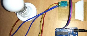
For the experiment, we will need a 220 Volt incandescent lamp and a simple plug with a cord. We connect the lamp with the cord in only one place:
We insert our solid state relay into the gap
We plug the plug into the socket and...
No... he doesn’t want to... Something is missing...
Not enough control voltage! We output voltage from the Power Supply from 3 to 32 Volts DC voltage. In this case, I took 5 Volts. I apply to control contacts and...
Oh miracle! The light came on! This means that contact No. 1 is closed with contact No. 2. The LED on the body of the relay itself also tells us that the relay is triggered.
I wonder how much current the relay control contacts consume? So, we have 5 Volts on the block.
And the current turned out to be 11.7 milliamps! You can even control it with a microcontroller!
Single Phase Phase Controlled Solid State Relays
Relay Features
- Output voltage adjustment (power regulator)
- Analog control signals: 4-20mA, 1-10V DC, variable resistor 470-560kOhm
- No contact bounce or sparking during switching
- No acoustic noise
- Low power consumption
- High performance
Decoding of nomenclature
- GDH – Type of solid state relay
- GDH – single-phase solid state relay (10 – 120A)
- GDM – single-phase solid-state relays in an industrial housing (100 – 500A)
- GDS – single-phase solid state relay (10 – 40A) for Din rail
- 40 – operating current 40A (from 10 to 500A)
- 48 – operating voltage 24-480V AC, 38 – 24-380V AC, 23 – 5-220V DC
- ZD3 – type of control signal (switching method)
- VA – variable resistor 470-560 kOhm/2W (phase control)
- LA – analog signal 4-20mA (phase control)
- VD – analog signal 0-10V DC (phase control)
- ZD3 – control 3-32V DC (switching at zero crossing)
- ZA2 – control 70-280V AC (switching at zero crossing)
Design options
| Output voltage | Analog signal | Rated switching current | ||
| 10A | 25A | 40A | ||
| 380V AC phase control | 4-20mA | GDH1038LA | GDH2538LA | GDH4038LA |
| 0-10V DC | GDH1038VD | GDH2538VD | GDH4038VD | |
| 470-560kOhm | GDH1038VA | GDH2538VA | GDH4038VA | |
| Output voltage | Analog signal | Rated switching current | |||
| 60A | 80A | 100A | 120A | ||
| 380V AC phase control | 4-20mA | GDH6038LA | GDH8038LA | GDH10038LA | GDH12038LA |
| 1-10V DC | GDH6038VD | GDH8038VD | GDH10038VD | GDH12038VD | |
| 470-560kOhm | GDH6038VA | GDH8038VA | GDH10038VA | GDH12038VA | |
Technical characteristics and operating conditions
| Modification of solid state relay | GDHxxxxxxLA | GDHxxxxxxVD | GDHxxxxxxVA |
| Switching voltage | 24-380V AC | ||
| Control signal | 4-20mA | 0-10V DC | 470-560kOhm/2W |
| Current consumption in the control circuit | — | <4mA | — |
| Leakage current (off state) | ≤5mA | ||
| Maximum peak voltage | 1000V AC | ||
| Voltage drop in load circuit | ≤1.6V AC | ||
| Switching time | ≤10ms | ||
| LED indication | absent | ||
| Breakdown voltage | 2500V AC during 1 minutes | ||
| Insulation resistance | 500MOhm at 500V DC | ||
| Ambient temperature | -30…+75°C | ||
| Relative humidity | ≤95% (no condensation) | ||
| dimensions | 57.5x44x32mm | ||
| Installation method | Screws onto mounting surface | ||
| Weight | ≤135g | ||
Note: The power and control terminals of the GDHxxxxxxVA are not isolated from each other. Be careful when working!
Connection diagrams
GDHxxxxxxLA, GDHxxxxxxVD
GDHxxxxxxVA
Appearance and overall dimensions
Pros and cons of solid state relays
pros
- turning circuits on and off without electromagnetic interference
- high performance
- absence of noise and contact bounce
- long period of operation (over a BILLION operations)
- possibility of working in explosive environments, since there is no arc discharge
- low power consumption (95% (!) less than conventional relays)
- reliable isolation between input and switched circuits
- Compact, sealed design, resistant to vibration and shock loads
- small size and good heat dissipation (if, of course, you use thermal paste and a good heatsink)
Minuses:
- high cost


