Determining the polarity of wires is an important skill that is necessary for all advanced equipment users and car enthusiasts. Confusion with minus and plus will, at best, lead to incorrect operation of the device. At worst, it will completely fail or explode due to battery overheating. However, such consequences are easy to prevent, since plus and minus on the wires can be determined in several ways, including without special equipment.
Basic methods for checking cable polarity
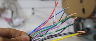
The easiest method to determine the plus and minus on a wire is a visual inspection. First of all, the presence of markings and color are assessed. However, the visual method does not always give results. Then the test is carried out using special instruments. As a last resort, you can use a simple battery or lamp. If you don't have anything suitable at hand, you can check the polarity with potatoes or water. Sometimes the charge is determined by a computer fan.
How phase wires are painted
When working with wiring, phase wires pose the greatest danger. Touching the phase, under certain circumstances, can become lethal, which is probably why bright colors were chosen for them. In general, the colors of electrical wires allow you to quickly determine which of a bunch of wires are the most dangerous and work with them very carefully.
Coloring of phase wires
Most often, phase conductors are red or black, but other colors are also found: brown, lilac, orange, pink, purple, white, gray. Phases can be painted in all these colors. It will be easier to deal with them if you exclude the neutral wire and ground.
In the diagrams, phase wires are designated by the Latin (English) letter L. If there are several phases, a numerical designation is added to the letter: L1, L2, L3 for a three-phase 380 V network. In another version, the first phase is designated by the letter A, the second by B, and the third by C .
How to Determine Polarity Using Raw Potatoes
Take a raw potato and cut it in half.
We plug our two wires from an unknown DC source into it and wait 5-10 minutes.
A light green color appears on the potato near the positive terminal.
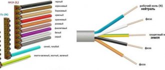
Three-wire system
Let's look at a cross-section of a three-core wire, which is used for laying household electrical networks.
The color of the wires indicates where the phase, neutral and ground are located. Additionally, the figure shows typical letter symbols used in electrical circuits. By picking up such a drawing, you can visually determine the correctness of the connection.
Let's take a look at GOST and see how well the color coding of wires shown in the figure meets the requirements. Clause 5.1 of the general provisions describes the twelve colors that must be used for marking.
The specified circuit is used for single-phase connection, suitable for most electrical appliances. It is almost impossible to get confused in it, with a correctly marked wire.
Expert opinion
Viktor Pavlovich Strebizh, lighting and electrical expert
Any questions ask me, I will help!
The only acceptable option is to use blue and cyan insulation to indicate the negative pole or midpoint in DC circuits. If there is something you don’t understand, write to me!
Colors for 220V and 380V networks
Installation of single- and three-phase electrical networks is facilitated if the wiring is made with multi-color wire. Previously, a flat two-core white wire was used for single-phase residential wiring. During installation and repair, to eliminate errors, it was necessary to ring each core individually.
The production of cable products with colored cores in different colors reduces the labor intensity of the work. To indicate phase and zero in single-phase wiring, it is customary to use the following colors:
- red, brown or black – phase wire;
- other colors (preferably blue) – neutral wire.
The phase markings in a three-phase network are slightly different:
- red (brown) – 1 phase;
- black – 2 phase;
- gray (white) – 3 phase;
- blue (cyan) – working zero (neutral)
- yellow-green – grounding.
Domestic cable products comply with the standard for core coloring, so a multiphase cable contains differently colored cores, where the phase is white, red and black , the neutral is blue , and the ground is yellow-green conductors.
When servicing networks installed according to modern standards, it is possible to accurately determine the purpose of the wires in the junction boxes. If there is a bundle of multi-colored wires, the brown one will definitely be phase. The neutral wire in distribution boxes has no branches or breaks. The exception is branches to multi-pole switching devices with complete circuit breaking.
How to check the correctness of marking and wiring
Wire colors in electrical engineering are designed to speed up the identification of conductors, but relying only on colors is dangerous - they could be connected incorrectly. Therefore, before starting work, you should make sure that you have correctly identified their affiliation.
Take a multimeter and/or an indicator screwdriver. It’s easy to work with a screwdriver: when you touch a phase, the LED built into the housing lights up. So it will be easy to identify phase conductors. If the cable is two-wire, there are no problems - the second conductor is zero. But if the wire is three-wire, you will need a multimeter or tester - with their help we will determine which of the remaining two is phase and which is zero.
Determining the phase wire using an indicator screwdriver
We set the switch on the device so that the selected jackal is more than 220 V. Then we take two probes, hold them by the plastic handles, carefully touch the metal rod of one probe to the found phase wire, the second to the supposed zero. The screen should display 220 V or the current voltage. In fact, it may be significantly lower - this is our reality.
If 220 V or a little more is displayed, this is zero, and the other wire is presumably “ground”. If the value is less, we continue checking. With one probe we again touch the phase, with the second - to the intended grounding. If the instrument readings are lower than during the first measurement, there is “ground” in front of you and it should be green. If the readings turn out to be higher, it means that somewhere there was a mistake with “zero” in front of you. In such a situation, there are two options: look for exactly where the wires were connected incorrectly (preferable) or simply move on, remembering or noting the existing position.
So, remember that when testing a phase-zero pair, the multimeter readings are always higher than when testing a phase-ground pair.
And, in conclusion, let me give you some advice: when laying wiring and connecting wires, always connect conductors of the same color, do not confuse them. This can lead to disastrous results - at best, equipment failure, but there may also be injuries and fires.
General concepts about the device
Car receivers are divided into two types depending on the method of their installation:
- Stationary - suitable for certain car brands due to their original shape and non-standard size. Such models are built into the car at the assembly stage. For example, such a model is the standard radio on the Chevrolet Cruze DWGM1001 or the Subaru Clarion model installed on the Subaru Impreza.
- Built-in - universal receivers, most have a removable front panel to protect against theft. An example of such models are Pioneer players.
The connectors of the device also play an important role. There are many types of connectors, the most preferred is the ISO standard. If the connectors do not match, you must purchase a corresponding adapter.
The essence of the operation of a car radio and its switching is in the following sequence:
- The negative of the battery is connected directly to the receiver.
- The voltage from the battery positive cable is sent to the fuse, and then the power goes to the branch: permanently connected + 12V power, as well as to the ignition key
- Through the positive cable of the ignition switch, current flows to the control terminal
Installation of the device is carried out by connecting the appropriate wires, and this requires an understanding of the polarity of the receiver.
Ground wire color
By modern standards, the ground conductor is yellow-green. It usually looks like yellow insulation with one or two longitudinal bright green stripes. But there are also transverse yellow-green stripes in color.
Grounding may be this color
In some cases, the cable may only have yellow or bright green conductors. In this case, the “earth” has exactly this color. It is displayed in the same colors on diagrams - most often bright green, but it can also be yellow. Signed on diagrams or on ground equipment in Latin (English) letters PE . The contacts to which the “ground” wire must be connected are also marked.
Sometimes professionals call the grounding wire “neutral protective”, but do not be confused. This is an earthen one, and it is protective because it reduces the risk of electric shock.
What color is the neutral wire?
Zero or neutral is blue or light blue, sometimes blue with a white stripe. Other colors are not used in electrical engineering to indicate zero. It will be like this in any cable: three-core, five-core or with a large number of conductors.
What color is the neutral wire? Blue or cyan
“Zero” is usually drawn in blue on diagrams and signed with the Latin letter N. Experts call it a working zero, since, unlike grounding, it participates in the formation of the power supply circuit. When reading a diagram, it is often defined as "minus", while the phase is considered "plus".
Manual color marking
It is used in cases where during installation it is necessary to use wires with cores of the same color. This also often happens when working in old houses, in which electrical wiring was installed long before the advent of standards.
Marking of two-core wires
If the cable is already connected to the network, then to search for phase wires, electricians use a special indicator screwdriver - its body has an LED that lights up when the tip of the device touches a phase.
True, it will only be effective for two-wire wires, because if there are several phases, then the indicator will not be able to determine which one is which. In this case, you will have to disconnect the wires and use a dialer.
Next, you will need a set of special tubes with a heat-shrinkable effect or insulation tape to mark the phase and zero.
The standards do not require such markings to be made on electrical conductors along their entire length. It is allowed to mark it only at the places of joints and connections of the necessary contacts. Therefore, if there is a need to apply marks on electrical cables without markings, you need to purchase materials in advance to mark them manually.
The number of colors used depends on the scheme used, but there is still a main recommendation - it is advisable to use colors that eliminate the possibility of confusion. Those. Do not use blue, yellow or green marks for phase wires. In a single-phase network, for example, the phase is usually indicated in red.
Marking three-wire wires
When phase, zero and ground are determined, markings can be applied. According to the rules, a yellow-green colored wire is used for grounding, or rather a core with this color, so it is marked with electrical tape of suitable colors. Zero is marked, respectively, with blue electrical tape, and the phase is any other.
If during preventive maintenance it turns out that the marking is outdated, it is not necessary to change the cables. In accordance with modern standards, only electrical equipment that has failed can be replaced.
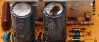
What does the blue stripe on the electrical wire mean? L and N in electrics - color coding of wires
Example: computer power supply or car wiring.
Expert opinion
Viktor Pavlovich Strebizh, lighting and electrical expert
Any questions ask me, I will help!
The marking is preserved along the entire length; sometimes cambrics or electrical tape are used at the connection points to better fix the element. If there is something you don’t understand, write to me!