Correct identification of conductors is needed to solve various practical problems. If you correctly determine the “red black plus minus” correspondence, the normal functioning of the audio speakers will be ensured. Errors in power networks when determining “phase” and “zero” are accompanied by significant damage and emergency situations. The information presented below will help eliminate incorrect actions during installation work.
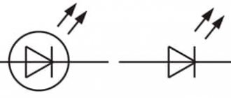
Color coding helps determine polarity when connecting test probes
Yellow-green grounding
The grounding conductor, or earth, serves for safety. The name comes from the fact that through this connection a dangerous charge (for example, formed on the body of a faulty device) instantly flows into the ground. Thus, grounding protects a person from electric shock.
There may not be a grounding wire in single-phase networks of old buildings, but this is becoming less and less common - during repairs, electricians recommend and install a network with ground.
Most often, the insulation of the ground wire is yellow-green. Sometimes the wire is only yellow or white with a green stripe. Grounding is marked with the letters “PE” - from the English “protective earthing” (protective grounding). But on diagrams, housings and terminal blocks it may be indicated not by letters, but by special symbols (see table).
ADVICE:
There is no complete guarantee that the wires in your home are connected in accordance with the colors - the human factor occurs in any area. In addition, the insulation of the wires may be the same color. In this case, you can also handle it yourself - an indicator screwdriver will help. This is a very simple tool that can be purchased at almost any hardware store.
The transparent handle of this screwdriver has a neon light or LED. At the end of the handle there is a contact plate on which you need to keep your finger during testing. If you touch the exposed wire of a live phase with a metal tip (probe) of a screwdriver, the light bulb will light up, but if there is no zero wire, it will not.
How to correctly determine the polarity on wires in a car
If the voltage on the car is checked, the course is set to search for a constant one. 20W is the correct setting if you are testing the battery. Therefore, you need to adjust the dial to the desired range/setting and connect the probes to whatever component you want to get a reading for.
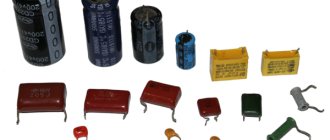
You may be interested in: Features of capacitor calculation
How to check a headlight with a multimeter
Multimeter
To check the headlight wiring, you need to find the ground wire. There are 2-4 wires coming from the connector that connects to the light bulb. Where there are two or three wires, only one of them is ground, while four-wire connectors will have two grounds.
To test the wires on the headlight, you need to set the multimeter to resistance. You can place one of the probes on the ground and the other on the negative pole of the car battery.
Note! If continuity is not read, then there is a problem with the ground wire, meaning it needs to be replaced.
How to Test a Car's Ground Wire Using a Multimeter
To test ground wires, start by measuring resistance. Test along the wiring to check the reading is 5 ohms or less. If it exceeds, you will need to check the wire further. You need to switch the multimeter to constant voltage and turn on any electrical part that is having problems. It's worth double-checking the wire to make sure the reading doesn't exceed 0.05V. If it does, you'll need to use a different ground location or use a tie strap.
How to Check if a Fuse Has Blown Using a Multimeter
Troubleshooting a fuse using a multimeter is extremely easy. You need to set the multimeter to the lowest ohm setting and place the probes on both sides of the fuse covers. Fuses do not have polarity, so the contacts used will not show values.
Circuit breakers
Note! If the resistance value is very low, then the fuse is working perfectly. If the resistance value does not change after connecting the contacts, the fuse has blown.
You can also test the fuse using a test light. You need to turn on the key and touch both sides of the fuse with the tip of the test light. If it lights up, the fuse is good. If it does not light up, the fuse needs to be replaced.
How to use a multimeter from a car battery
If you're having trouble starting your car, one of the most common reasons is a weak battery. This is something that can be easily checked using a multimeter, which will also give an accurate idea of how much charge the battery actually has left. Testing your car battery first is a great way to rule out a likely cult for many electrical problems.
When testing a car battery, you need to check the voltage by setting the multimeter to 20 V DC. It is necessary to connect contacts to both terminals of the battery that match the color. It is better to turn on the headlights to get accurate information regarding the charge.
Important! The headlights must be turned on when the engine is stalled.
In most cases the reading will be somewhere between 11.8 V and 12.6 V. The higher the voltage reading, the more charge there is in the battery. A reading of 12.5V means the battery is almost fully charged, while a reading of 11.9V means the battery should be replaced soon.
You may be interested in this: Learning to read electrical diagrams
Checking the charger
Electronic devices use adapters to convert alternating current supplied from wall outlets to direct current. Once converted to direct current, current flows in one direction, hence the term direct current.
What color is the positive wire on the charger?
Note! One wire is positive, which conducts current to the device, and the other is negative, which completes the circuit. The direction of flow is called polarity and is marked on chargers using a diagram. If there is no diagram on the charger, it is worth checking the polarity.
The color polarity of the charger wires does not matter.
To determine if the charger is fit for use, do the following:
- Connect the charger to a power outlet.
- Turn on the multimeter and set the settings to DC voltage. Most multimeters indicate this setting as VDC.
- Insert the red positive contact into the hole in the charger tip.
- Touch the black negative terminal and the outer metal part of the charger tip.
- Monitor the multimeter readings. You may see a positive or negative number indicating the DC output voltage of the charger. If the number is positive, then the polarity on the inside of the charger tip is positive. If the number is negative, then the polarity inside is negative.
Description of poles
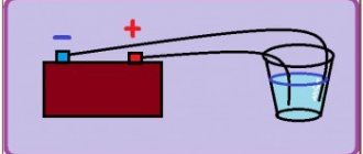
In the case of an electric current passing between two points, or poles, one of the poles will have more electrons than the other. The pole with more electrons is said to have a negative charge. The pole with fewer electrons has a positive charge. When two poles are connected by a wire, electrons move from the negative pole to the positive pole. This flow is called electric current.
Polarity can be of different types
For your information! In a DC circuit, one pole is always negative and the other positive with electrons flowing in only one direction. In an alternating current (AC) circuit, the two poles alternate between negative and positive poles with the electrons flowing in the opposite direction.
Pinout diagrams for charging tablets
Almost any tablet computer requires a large current to charge - 2 times more than a smartphone, and charging through the mini/micro-USB socket in many tablets is simply not provided by the manufacturer. After all, even USB 3.0 will not provide more than 0.9 amperes. Therefore, a separate nest (often round type) is placed. But it can also be adapted to a powerful USB power source if you solder an adapter like this.
Useful: Pinout of HDMI cable and connector, pinout diagram
Colors for 220V and 380V networks
Installation of single- and three-phase electrical networks is facilitated if the wiring is made with multi-color wire. Previously, a flat two-core white wire was used for single-phase residential wiring. During installation and repair, to eliminate errors, it was necessary to ring each core individually.
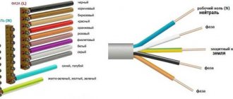
The production of cable products with colored cores in different colors reduces the labor intensity of the work. To indicate phase and zero in single-phase wiring, it is customary to use the following colors:
- red, brown or black – phase wire;
- other colors (preferably blue) – neutral wire.
The phase markings in a three-phase network are slightly different:
- red (brown) – 1 phase;
- black – 2 phase;
- gray (white) – 3 phase;
- blue (cyan) – working zero (neutral)
- yellow-green – grounding.
Domestic cable products comply with the standard for core coloring, so a multiphase cable contains differently colored cores, where the phase is white, red and black, the neutral is blue, and the ground is yellow-green conductors.
When servicing networks installed according to modern standards, it is possible to accurately determine the purpose of the wires in the junction boxes. If there is a bundle of multi-colored wires, the brown one will definitely be phase. The neutral wire in distribution boxes has no branches or breaks. The exception is branches to multi-pole switching devices with complete circuit breaking.
Marking of wires for alternating three-phase current
The special color designation of the shell helps to determine the purpose of individual lines even without studying the accompanying design documentation:
- gray, purple, orange or red wire – phase;
- yellow and green stripes – grounding;
- blue or a combination of white and blue stripes is neutral.
Such designations simplify installation operations when laying power lines, during the assembly of electrical panels
It is especially important to eliminate errors when hidden installation of communications inside building structures is used. In this case, correcting incorrect actions will be accompanied by increased costs
What color are the poles in the wires?
The protective neutral cable connects the protective ground and N-neutral cables. These types require double grounding along the line. The marking of electrical wires is the same as for the protective conductor, yellow-green. Blue color was also used in older installations, but nowadays such markings are rare. It is much more common to see installations marked with alternative yellow and green stripes.
Note! The very tip of the protective neutral cable is usually marked blue.
The neutral cable is found in very old electrical installations. It was used in cases where circuits did not yet have neutral and protective cables. The installation only had phase and ground neutral wires, which could be identified by their blue color. Today, the neutral conductor is no longer used in electrical installations.
Green cable with positive potential
Green color is for electrical cables with positive potential.
In electronic devices, positive charge flows in the red wires, negative charge in the black wires.
Micro USB connector pinout
To begin with, we present the wiring for this specification.
Micro USB v 2.0 connector wiring
As can be seen from the figure, this is a 5 pin connection; both the plug (A) and socket (B) have four contacts. Their purpose and digital and color designation correspond to the accepted standard, which was given above.
Description of the micro USB connector for version 3.0.
For this connection, a characteristically shaped 10 pin connector is used. In fact, it consists of two parts of 5 pin each, and one of them fully corresponds to the previous version of the interface. This implementation is somewhat confusing, especially considering the incompatibility of these types. Probably, the developers planned to make it possible to work with connectors of earlier modifications, but subsequently abandoned this idea or have not yet implemented it.
MicroUSB connector layout for version 3.0
The figure shows the pinout of the plug (A) and the appearance of the micro USB socket (B).
Contacts 1 to 5 fully correspond to the second generation micro connector, the purpose of the other contacts is as follows:
- 6 and 7 – data transmission via high-speed protocol (SS_TX- and SS_TX+, respectively).
- 8 – mass for high-speed information channels.
- 9 and 10 – data reception via high-speed protocol (SS_RX- and SS_RX+, respectively).