An overhead power line (OHL) with a voltage of up to 1000 V is the most common and most vulnerable element of the energy distribution system, especially in rural areas, as well as among small towns and suburban areas of megalopolises. If you carefully study the statistics of accidents in power systems, you will notice the fact that the cause of 75-80% of emergency power line outages in spring and summer are thunderstorms.
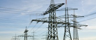
Figure 1. Power lines (PTL)
Basic concepts and definitions
Based on the “Rules for the Construction of Electrical Installations” (PUE, edition 6), the term “overhead line” refers to an overhead line made using bare wires. Based on what is written in the PUE (edition 7), power lines can be made using both insulated (VLI) and non-insulated wires.
In the seventh edition of the PUE, the term “VLI” is explained in this way - these are lines using self-supporting insulated wires (SIP). Let's consider how to organize lightning protection of overhead lines in practice. In this case, it is necessary to answer a fairly simple question: what exactly is the object of external protection of overhead lines from lightning?
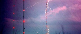
Figure 2. Lightning discharges over power lines
Ultimately, the object of external lightning protection of overhead lines made with bare wires is the electrical installations of the electricity consumer. Bare wires are not subject to protection at all; on overhead lines up to 1000 V, means of protecting wires from direct lightning strikes are usually not used. To significantly reduce the statistics of short circuits that occur between wires, VLI and SIP are used.
When using insulated wires when constructing power lines, the risks associated with short circuits due to overlapping and electrical contact of wires with trees are completely eliminated; the risk of ground faults due to falling wires is reduced. The use of VLI significantly reduces the contour area for the overvoltage induced by an electromagnetic lightning pulse, which brings the safety of such lines closer to the safety of an underground cable. It is also necessary to note electrical safety when carrying out work on the line, since the likelihood of electric shock is significantly reduced. In addition, the use of insulated wires significantly reduces the impact of discharges and reduces the likelihood of arc faults.
What processes occur in power lines with bare wires if they are hit by a direct lightning strike? First, you can see phase-to-ground discharges that occur between the wire itself and the support traverse, then, under the influence of the electromagnetic forces of the arc itself, these discharges move along the lines themselves. Burnout of bare wires does not occur due to the displacement of the ends of the arc along the lines.
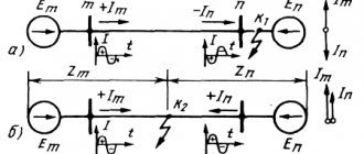
Figure 3. Processes on power lines with bare wires caused by a direct lightning strike
When such a physical phenomenon as a short circuit on an overhead line occurs, the processes accompanying it occur according to a completely different algorithm: the ignition of an arc is observed only between each individual conductor and the structure holding the wires on the support. The insulation layer is a natural obstacle to the freely moving arc, and the arc therefore burns only at a specific point, as a result of which the wire is burned out.
Figure 4. Short circuit to VLI
Short circuits on the overhead line trigger the automation and lead to the line being disconnected. There are other threats - these are overvoltage spreading along the line. To protect against them, surge suppressors (SPDs) and surge protection devices (SPDs) are used.
Modern aspects of increasing the lightning resistance of power lines
Introduction
Lightning overvoltages on high-voltage lines (OHL) arise as a result of a direct lightning strike in an overhead line (to a support, a lightning protection cable, a phase wire) and as a result of the action of induced voltage during a lightning strike on objects near the overhead line (trees, buildings). At the same time, overvoltages occur on the linear insulation, leading to the so-called airborne insulation flashover (insulation flashover). Overlapping insulation can lead to the occurrence of a stable power arc - a stable short circuit (short circuit) of the phase to ground. A number of methods establish the probability of establishing a power arc (stable short circuit) to be slightly less than 1 during a pulsed overlapping of the insulation of a 110 kV overhead line in networks with a grounded neutral [2, p. 70]. As a result, relay protection and substation automation (RP&A substation) are triggered, disconnecting the short circuit on the overhead line. The line becomes de-energized, and consumers do not receive enough electricity.
Operating experience shows that lightning outages of overhead lines on average account for 10 ÷ 20% of the total number of automatic shutdowns for all reasons. As the rated voltage class increases, the number of lightning outages decreases, but their share (relative to outages for all reasons) increases against the backdrop of an increase in the overall reliability of overhead lines. [1, p.154]
It is important to ensure a constant supply of electricity to the consumer, to increase the lightning resistance of overhead lines, that is, to increase the resistance of overhead lines to the effects of lightning overvoltages.
In a number of projects recently, the use of surge arresters (OSL) with the simultaneous refusal to install lightning protection cables is considered as an alternative method for increasing the lightning resistance of overhead lines.
This article analyzes the main means of ensuring lightning resistance of overhead lines and proposes an integrated approach based on modern achievements and developments.
Methods for increasing lightning resistance of overhead lines
A general idea of the proportion of lightning strikes at points ① ② ③ (see Figure 1) is shown in Table 1. [2, p.15]
Picture 1
Table 1. Proportions of lightning discharges into various elements of overhead lines
| Dot | Lightning strike location | There is no lightning protection cable | There is a lightning protection cable |
| ① | Phase Wire | 0,5 | 0,005 |
| ② | Support or lightning protection wire close to the support | 0,5 | ≈0,5 |
| ③ | Lightning protection cable in the middle part of the span | 0 | ≈0,5 |
| Total: | 1,0 | 1,0 | |
The most dangerous is a direct lightning strike to a phase wire. The overvoltage wave goes towards the substation, some of it is lost to losses in the corona when traveling along the phase wire, the insulation of the phase wire overlaps, which in turn leads to the occurrence of a stable short circuit and shutdown of the overhead line relay protection and automation of the substation, with a certain degree of probability of each subsequent event occurring .
It follows from the table that a lightning protection cable installed on an overhead line reduces the probability of a lightning strike to phase wires hundreds of times, thereby leading in some cases to a significant increase in the lightning resistance of overhead lines 35 ÷ 750 kV.
When lightning strikes a support or lightning protection cable (grounded parts of an overhead line), insulation overlap may occur due to an increase in the impulse potential on the crossarm at the point where the insulating suspension of the phase wire is attached to the support. This insulation overlap is called “reverse overlap” - overlap from the grounded part of the electrical installation to the current-carrying one.
The critical values of lightning current leading to overlapping of linear insulation during lightning breakthroughs on wires are small. The insulation of overhead lines 110 ÷ 330 kV is blocked at a lightning current amplitude from 3 to 10 kA and above. For insulation of overhead lines 500 ÷ 1150 kV, lightning current from (15 – 35) kA is dangerous. Almost every lightning strike on a 110 kV overhead line causes an insulation flashover. When lightning breaks through the wires of a 1150 kV overhead line, 30 ÷ 40% of lightning discharges are dangerous. Thus, the high impulse strength of linear insulation of overhead lines 500 ÷ 1150 kV does not ensure their lightning resistance in case of lightning breakthroughs on the wires. [1, p.145]
Reverse flashovers occur at a significantly higher amplitude of the lightning current. For example, the insulation of a 110 kV overhead line is blocked when lightning strikes a support with a current reaching several tens of kiloamperes. When the lightning strike point moves away from the support to the middle of the span, the probability of reverse insulation flashover decreases due to the distribution of the lightning current between the two supports, a decrease in the current slope due to losses due to the impulse corona when traveling along the cable and the distance of the lightning channel. [1, p.146]
The main means of lightning protection for overhead lines are:
- suspension of grounded cables
- reduction of grounding resistance of supports
- increasing the impulse strength of linear insulation
- protection of individual supports and areas with weakened insulation
- Non-linear surge suppressors (OSN)
A backup means of increasing the reliability and uninterrupted operation of overhead lines is automatic reclosure (AR), especially high-speed (BARES) and single-phase (SARES). The success rate of automatic reclosure during lightning outages, according to operating experience, for overhead lines 110 ÷ 500 kV averages 0.6 ÷ 0.8, and for overhead lines 750 and 1150 kV – 0.8 ÷ 0.9. Automatic reclosure allows you to partially compensate for the low lightning resistance of overhead lines when it is difficult to install good grounding, etc. However, the use of automatic reclosure should not exclude the use of basic lightning protection means, since short circuits reduce the service life of substation equipment . [1, p.148]
Suspension of grounded cables is the most effective and widespread way to increase lightning resistance. The location of the cables relative to the wires should ensure the greatest effectiveness of cable protection for the prevailing type of lightning outages for a given overhead line (breakouts or reverse flashovers). In the first case, reducing the probability of a breakthrough is achieved by reducing the protection angle of the cable(s), including suspending the cables with a negative protection angle, and increasing the vertical distance between the cable and the wire. In the second case, the probability of reverse overlap decreases with an increase in the number of cables, their separation over a greater distance, including when part of the cables are suspended under the wires. The listed measures help reduce the pulse current through the support and enhance the electrostatic shielding of the wires with cables. [1, p.148]
Reducing the grounding resistance of overhead line supports with a cable is one of the main means of reducing the likelihood of a pulsed insulation flashover when a lightning strikes a cable or support. The exception is overhead lines or areas on very high supports (river crossings, etc.), the lightning resistance of which is largely determined by the inductance of the supports. [1, p.149]
In situations with high grounding resistance of supports, an important advantage is the use of lightning protection cables based on steel wires clad with aluminum (Fig. 2) of the GTK brand, instead of galvanized lightning protection cables of the MZ brand.
Rice. 2. Sketch of lightning protection cable brand ГТК
This is due to the fact that the resistance of the GTK is significantly lower than the resistance of galvanized cables, which will contribute to the spread of lightning current (or short circuit) over adjacent supports and will reduce the likelihood of insulation overlap, and therefore an emergency shutdown.
The need for non-traditional additional means of increasing the lightning resistance of overhead lines arises when the effect of increasing the lightning resistance of overhead lines using basic means (cables, grounding of supports, increasing the insulation strength) is insufficient or their implementation is not economically feasible.
An additional means of increasing the lightning resistance of overhead lines can be surge arresters installed directly on overhead line supports. The use of surge arresters in addition to lightning protection cables on overhead lines is most effective in the following cases:
- on one of the circuits of a double-circuit overhead line, which almost completely prevents lightning outages of two circuits at the same time (it is often practiced to supply a responsible consumer via a double-circuit overhead line);
- with high grounding resistance of supports (permafrost soils, rocks, dry sand);
- on high supports (crossing water barriers). [1, p.150]
Economic calculations show that protecting the entire overhead line route using surge arresters without using a lightning protection cable will cost more than installing (replacing with a new one) a traditional lightning protection cable. With such a lightning protection scheme (no cable - there is an arrester), the current and energy passing through the arrester during a lightning strike in an overhead line are high, increasing the risk of damage to the installed arresters. In this case, it is necessary to use so-called “heavy” surge arresters, with high current throughput values (> 1000 A), which in turn entails a significant increase in the cost of the project.
During the construction and reconstruction of 110 ÷ 750 kV overhead lines, the mass installation of surge arresters on supports should be considered as an additional means of increasing lightning resistance, the need for which must be technically and economically justified. [2, p.38]
A counterargument for installing a lightning protection cable, as a rule, is the opinion that when severe climatic conditions occur (a thick layer of ice on the wires, galloping, etc.), the lightning protection cable may approach an unacceptably short distance to the phase wires or a break may occur when the load increases. However, with a competent approach to design and installation, this scenario seems unlikely, since at the design stage appropriate calculations must be carried out in order to exclude the occurrence of such events: selection of an appropriate lightning protection cable design, taking into account climatic conditions and the distance between supports, as well as mechanical calculations (tension, sag, assembly tables); calculations to ensure compliance with the minimum permissible insulation distances between the lightning protection cable and phase wires when exposed to various climatic conditions and the occurrence of dancing; calculation of loads on supports; calculation of vibration damping circuit. Installation of the lightning protection cable must be carried out in full accordance with the design.
From the materials of the VI All-Russian Conference on Lightning Protection (St. Petersburg, April 17-19, 2022), the following conclusions can be drawn about the results of using surge arresters without lightning protection cables: – economic inefficiency of using surge arresters and worsening statistics on lightning outages over time; – failure of the surge arrester due to a lightning strike in the immediate vicinity of the installation site, a large number of shutdowns due to damage to the arrester of the first generations; – the occurrence of emergency situations on overhead lines due to defective materials and installation errors when installing surge arresters.
Thus, the widespread installation of relatively cheap, but low-power surge arresters does not lead to a reduction in the accident rate on overhead lines due to lightning overvoltages, and the installation of powerful, but expensive surge arresters on each support and all phase wires is economically ineffective. Only comprehensive protection of overhead lines using lightning protection cables and spot installation of surge arresters in the most critical spans leads to the lowest possible indicators for lightning outages with acceptable economic efficiency.
Lightning strike to lightning protection cable and phase wire
In STO 56947007-29.060.50.015-2008 “Lightning protection cables for overhead power lines 35-750 kV. Technical requirements" Section 5.3 provides requirements for the electrical parameters of lightning protection cables. Thus, clause 5.3.4 states that the lightning protection cable must be resistant to the effects of a lightning current pulse with a constant component carrying a charge, the value of which is determined in coulombs for each lightning resistance class GT when a tensile load is applied to the lightning protection cable equal to [SEL + 5% MPR] , where SEN is the average operating load, MPR is the maximum tensile strength. [4, p.9]
Thus, lightning protection cables are divided into 5 classes according to lightning resistance (“class 0” – 50 kL… “class 4” – 150 kL) and there are certain methods for identifying this parameter in a lightning protection cable.
In other words, when a lightning strike of a certain force strikes a lightning protection cable, the latter must withstand and not break under a certain applied load.
For wires used as power phase conductors (AC, etc.), there is no such requirement and, accordingly, there is no methodology for identifying lightning resistance. It is believed that the main purpose of a phase wire is the transmission of electricity, and the main purpose of a lightning protection cable is to protect overhead lines from a direct lightning strike.
As practice shows, when lightning strikes an AC phase wire, the wires of the top layer are destroyed and unraveled, and the more powerful the lightning impact, the more wires are destroyed. This leads to a number of negative consequences:
- A significant increase in the resistance of the damaged section of the phase wire, as a result, the wire can heat up above the permissible norm.
- The mechanical strength of the wire decreases.
- Unraveled wires can approach an unacceptable distance to other elements of the overhead line, thereby significantly increasing the likelihood of a short circuit and emergency shutdown of the overhead line.
It should be noted that when a lightning strike strikes a suspended lightning protection cable, in rare cases it may be destroyed, but this situation has less negative consequences than a lightning strike on a phase wire that is weaker in terms of lightning resistance and is more likely to be damaged. The operation of a phase wire in a span during severe climatic conditions (ice, wind, dancing, galloping, etc.) may be aggravated due to a decrease in its mechanical strength and an increase in resistance (heating the wire above normal leads to destruction of the wire), which can lead to a further accident on Overhead lines and expensive repairs.
Requirements for “electrical installation rules”
PUE-7, paragraph 2.5.116 states that “Overhead lines 110 ÷ 750 kV with metal and reinforced concrete supports must be protected from direct lightning strikes by cables along the entire length.
The construction of 110-500 kV overhead lines or sections thereof without cables is permitted:
1) in areas with less than 20 thunderstorm hours per year and in mountainous areas with a ground discharge density of less than 1.5 per 1 km2 per year;
2) in areas of overhead lines in areas with poorly conductive soils (r > 103 Ohm m);
3) on sections of the route with an estimated ice wall thickness of more than 25 mm;
4) for overhead lines with reinforced insulation of the wire relative to the grounded parts of the support, while ensuring the estimated number of lightning outages of the line corresponding to the estimated number of lightning outages of an overhead line of the same voltage with cable protection.
The number of lightning line outages for the cases given in paragraphs 1-3, determined by calculation taking into account operating experience, should not exceed three per year for 110 ÷ 330 kV overhead lines and one per year for 500 kV overhead lines without strengthening the insulation.
Overhead lines 110 ÷ 220 kV, intended for power supply to oil and gas production and transportation facilities, must be protected from direct lightning strikes by cables along the entire length (regardless of the intensity of lightning activity and equivalent resistivity of the earth).” [3]
Thus, the requirements of regulatory documentation directly establish the need to install lightning protection cables along the entire length of the route, except in special cases. It is not allowed to refuse to install a lightning protection cable in favor of an arrester as the main means of lightning protection.
FOCL to overhead line
Overhead power lines have long been popular for carrying communication lines. Aerial laying of communication cables (suspension) is one of the most economical ways to organize communication, since you can use existing supports without building a separate infrastructure. But old supports may not be able to withstand the additional load from hanging a separate communication cable. Moreover, an additional cable means additional costs for materials, installation and maintenance.
On the other hand, the previous sections concluded that a lightning protection cable on overhead lines is necessary. Lightning protection cable is a metal cable suspended at the highest point of the power line above the phase wires to protect against lightning strikes, a natural element of power lines. At the same time, most of the time it is without voltage, with the exception of moments when it is affected by a lightning strike or a short circuit with a phase wire occurs. Since optical fiber is not subject to electromagnetic influence, the idea arose to connect a lightning protection cable with an optical cable, solving two problems simultaneously - increasing the lightning resistance of overhead lines and data transmission. On overhead lines around the world, OPGW has become widespread - an optical cable built into a lightning protection cable, designed to protect overhead lines from direct lightning strikes, and also performs the function of a communication cable.
The introduction of optical fibers into the design of a lightning protection cable allows you to quickly and efficiently create high-speed modern information transmission lines on the power transmission line infrastructure. The use of ready-made infrastructure provides additional security for the communication line, reducing the accident rate - the ground wire hangs at the highest point of support above the live phase wires, which significantly limits unauthorized access to the line.
Today, OPGT is recommended by Rosseti PJSC as the main method of organizing communications on lines of 110 kV and above.
STO 56947007-33.180.10.172-2014 “Technological communications. Rules for the design, construction and operation of fiber-optic communication lines on overhead power lines with a voltage of 35 kV and above" clause 4.2.3: "To create fiber-optic communication lines on newly built or reconstructed and operating overhead lines, the most reliable and economically feasible is to hang the OPGW on the mounting points provided in the design of the supports . At the same time, the OPGT performs the function of a GT, protecting overhead lines from direct lightning strikes into phase wires, and, along with other measures, ensures lightning resistance of overhead lines, and also allows information to be transmitted via the built-in OC.” [5, p.19]
Thus, when using an optical cable built into a lightning protection cable, network energy companies not only receive protection from lightning strikes, but can also act as communication operators: optical fibers and channels can be rented, sold or operated independently.
Moreover, if melting of ice is organized on the overhead line, then the optical fibers built into the lightning protection cable can act as distributed sensors of the temperature measurement system along the OPGW. The temperature measurement system along the OPGW aims to prevent abnormal heating of the OPGW in the melting mode.
When fibers for monitoring deformation (laid without excess length) are used as part of OPGT, it is also possible to determine the onset of ice formation (or other various non-standard influences) on individual sections of the route with an accuracy of several meters. This system allows you to timely and effectively prevent emergency situations that may arise due to severe climatic conditions.
Conclusion
Lightning protection cable is a natural and integral element of overhead lines, providing protection of phase conductors from destruction due to direct lightning strikes. Surge arresters cannot be a replacement for lightning protection cable as the main means of ensuring lightning resistance. However, it is recommended to use surge arresters as an additional means of lightning protection in certain critical sections of the route.
The use of an optical cable built into a lightning protection cable allows you to increase the economic efficiency of using cable protection by creating a communication channel based on optical fibers. This does not require the use of separate communication cables, which increase the load on the supports and require additional costs for their installation and operation. Innovative methods for monitoring the state of OPGW based on optical fiber acting as a distributed sensor make it possible to timely determine the onset of ice formation and use the ice melting mode with temperature control along the route.
Literature:
- RD 153-34.3-35.125-99. “Guide to the protection of electrical networks 6 ÷ 1150 kV from lightning and internal overvoltages.”
- “Application of surge arresters to protect the insulation of overhead lines 6 ÷ 750 kV.” Dmitriev M.V.
- "Rules for electrical installations." 7th edition.
- STO 56947007-29.060.50.015-2008. “Lightning protection cables for overhead power lines 35-750 kV. Technical requirements".
- STO 56947007-33.180.10.172-2014. “Technological communication. Rules for the design, construction and operation of fiber-optic communication lines on overhead power lines with a voltage of 35 kV and higher."
Measures for the use of external lightning protection for overhead lines
The following can be considered as objects of protection of overhead lines (voltage up to 1000 V):
- equipment mounted on power transmission line supports, even if it has, for example, equipment for communication or alarm systems;
- branches from highways to building entrances;
- branches from highways to building entrances;
- insulation of power line wires.
In order to reduce the magnitude of carried lightning overvoltages and protect the branches from the main line to the inputs to the structures, it is necessary to install an SPD. In this case, the following happens: lightning currents are discharged, as a rule, through a grounded drain, which is mounted on a power line support in the charger. A PEN conductor is connected to the grounding device, as well as hooks of phase wires and other wires that can be suspended on power line supports and reinforcement of reinforced concrete supports of overhead lines.
Grounding requirements must also be observed. No more than 30 Ohms - this should be the resistance of the grounding device, according to the instructions of regulatory documents.
In order to calculate the correct distance between power poles, you need to know the average statistics on thunderstorm activity in a particular region. If for the whole year the average duration of thunderstorms was up to 40 hours inclusive (region 1), then the value of 200 m is taken. But if the average duration of thunderstorms is more than 40 hours per year (region 2), the value of 100 m is used. Additional equipment for charger used for the following objects: – on power transmission line supports with branches into buildings in which large crowds of people may gather (hospitals, cultural and sports facilities, educational institutions, etc.) or for objects with great material value. Additional charger equipment is used on the end supports of power lines with branches. Here the distance to the nearest charger is taken into account. For region 1 this figure is no more than 100 m, and for region 2 it should not be more than 50 m. Low-voltage valve gaps or spark gaps are also used as additional protective measures at the entrances to buildings or at the end supports of power lines.
Figure 5. Valve arrester
Measures for internal lightning protection of overhead lines
Let's consider in practice how internal lightning protection of power lines is designed. SPDs, potential equalization systems or potential equalization (if necessary) and grounding devices are used as such equipment.
Figure 6. Internal lightning protection (overvoltage protection) on power lines
There is a classification of SPDs into categories, depending on the test method and installation:
SPD type No. 1 is installed at the air entry into the building. If an external lightning protection system for power lines is installed, then surge protection devices in this embodiment can be used to remove a significant part of the direct lightning current.
Induced current pulses also have a negative impact on the system; to prevent them, a second type of surge protection device is used. These devices are installed after the first type of SPD or at the entrance to the structure.
The purpose of the third type of SPD is to protect important electrical equipment, such as medical devices, data processing systems, etc. The third type of surge protection devices is located, as a rule, no more than 5 m along the cable from the devices that are to be protected. The third type of SPD is in practice mounted as a hidden installation, for example, the devices can be located directly behind the socket or in the device housing. The purpose of the delay line is to optimally distribute the pulse power between all levels of the protective system. In practice, a choke (15 µH inductance) is used. If there is no inductor, you can take a piece of cable (15 m or more in length) with the same inductance.
Initially, a first-class SPD is triggered; most of the pulse energy is spent on it. Then the SPD (class 2) reduces the voltage to a value that is recognized as safe.
Physics of lightning discharge
Lightning is a type of gas discharge with a very long spark length. The total length of the lightning channel reaches several kilometers, and a significant part of this channel is located inside a thundercloud.
For a thunderstorm to occur, it is necessary, firstly, strong rising air currents and, secondly, the required air humidity within the thunderstorm zone.
Rising air currents arise due to the heating of layers of air adjacent to the earth's surface and the thermally determined heat exchange of these layers with cooled air at high altitudes.
Several clusters of charges are formed in the cloud, isolated from each other (in the lower part of the cloud, mainly charges of negative polarity accumulate), lightning is usually multiple, i.e. consists of several unit discharges developing along the same path.
The exact mechanism of charge separation in a thundercloud is still largely unclear. However, observations show that charge separation coincides with the freezing of water droplets in the cloud.
Normative base
When designing, installing, operating and repairing overhead lines with voltages up to 1000 V, you should be guided by the following documents:
- Electrical Installation Rules (ELI), edition 6 and 7.
- GOST R 51992–2011. Low-voltage surge protection devices. Part 1. (IEC 61643 – 1:2005).
- STO 56947007–29.240.02.001–2008. Guidelines for the protection of electrical distribution networks with a voltage of 0.4–10 kV from lightning overvoltages. Standard of JSC FGC UES.
- Technical circular of the association "Roselektromontazh" No. 30/2012 "On the implementation of lightning protection and grounding of overhead lines and overhead lines up to 1 kV."
When choosing regulatory documents, priority should be given to GOSTs of the Russian Federation (or international standards, if they are in the rank of direct application), followed by Guiding Materials (RD), departmental instructions and manuals, which, as a rule, are of a reference or advisory nature, expanding and supplementing the standards in relation to specific industry conditions.
The design, installation, operation and repair of overhead lines should be entrusted only to specialized organizations that have the appropriate licenses (special permits) or to individual individuals (individual entrepreneurs) who have the appropriate certificates (diplomas) with the right of admission to work with the relevant electrical installations.
Do you need advice on organizing grounding and lightning protection for your facility? Contact the ZANDZ.ru Technical Center!
