Residual energy: what is it?
All electrical machines are represented by reactive and active elements. They are the ones who consume electrical energy. These include reactive cable connections, capacitor and transformer windings.
During the flow of alternating current, reactive electromotive forces are indexed on these resistances, which create a reactive current.
Installations and devices that produce alternating current use reactive energy in the electrical network, which creates a magnetic field of an electric field.
Design and principle of operation of an electric meter
In this article we will tell you the structure and operating principle of an electric meter, to make it easier for you to perceive all the information, we have prepared basic diagrams and images for you. With their help you can find out what an electric meter consists of and how it works.
- Induction.
- Electronic.
Induction counter device
An induction meter consists of two main electromagnets, they are located at an acute angle of 90 degrees opposite each other. There is an aluminum disk in a magnetic field, and it is this that shows us the energy consumption.
To include the meter in the circuit, it is necessary to connect its current winding to all electrical receivers in series. The voltage winding is connected in parallel.
During the passage of electric current through the windings of an induction meter, alternating magnetic fluxes arise in the cores, they penetrate the aluminum disk and induce so-called eddy currents in it.
It will be interesting to know which meter is better to install in the house.
Eddy currents interact with magnetic fluxes and create forces, with the help of which the disk begins to spin. The disk is directly connected to a standard counting mechanism. Depending on the disk rotation speed, the consumed electrical energy is taken into account.
The following is the diagram of an electric meter.
Let's do a little decoding:
- Current windings.
- Voltage windings.
- Worm mechanism.
- Counting mechanism.
- Aluminum disc.
- A magnet that slows down the disk.
We have already looked at the diagram above, now look at what an electric meter looks like in cross-section (live).
If the electricity consumed is large, then three-phase induction meters are used, their operating principle is similar to single-phase ones. Watch the video to see how an electric meter works.
The influence of inductive reactance on the creation of a magnetic field
All devices that are powered from the mains have inductive reactance. It is thanks to him that the signs of current and voltage are opposite. For example, voltage has a negative sign and current has a positive sign, or vice versa.
At this time, the electrical energy created in reserve in the inductive element oscillates through the network due to the load from the generator and back. This process is called reactive power, which creates a magnetic field of an electric field.
Physics of the process
When we are dealing with DC circuits, there is no need to talk about reactive power. In such circuits, the values of instantaneous and total power are the same. The exception is the moments of switching on and off capacitive and inductive loads.
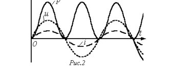
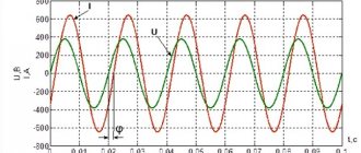
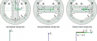
A similar situation occurs in the presence of purely active resistances in sinusoidal circuits. However, if devices with inductive or capacitive reactances are included in such an electrical circuit, a phase shift occurs in current and voltage (see Fig. 1).
In this case, a phase lag of the current is observed on inductances, and on capacitive elements the phase of the current shifts so that the current leads the voltage. Due to the violation of the current harmonics, the total power is decomposed into two components. Capacitive and inductive components are called reactive and useless. The second component consists of active capacities.
Rice. 1. Phase shift by inductive load
The phase shift angle is used when calculating the values of active and reactive capacitive or inductive powers. If the angle φ = 0, which occurs with resistive loads, then there is no reactive component.
Important to remember:
- the resistor consumes exclusively active power, which is released in the form of heat and light;
- inductors provoke the formation of a reactive component and return it in the form of magnetic fields;
- Capacitive elements (capacitors) cause the appearance of reactance.
Problems in reactive power generation
If there is a large share of reactive power generation in the network, then it is necessary:
- increase the power of power devices that are designed to convert electrical energy of one voltage value into electrical energy of another voltage value;
- increase the cable cross-section;
- combat the increase in power loss in power devices and transmission lines;
- increase charges for electricity consumption;
- combat voltage loss in the network.
Payment for reactive power
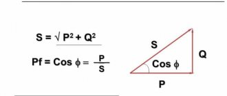
Legislation in the field of electric power industry provides for a rather impressive set of references to the need to pay the consumer to the network organization for reactive power, however, in fact, such payment is not currently being made. Let's figure out why this happens. The power triangle, known to everyone since school, creatively reworked in the illustration for this article, suggests that total power consists of active power, that is, going to useful work, as well as reactive power, which, accordingly, does not go to useful work . Essentially, reactive power is loss. The greater the reactive power, the more energy the network organization must transfer in order for the consumer's electrical installations to perform useful work. Logically, the consumer must either compensate the network organization for the costs of transmitting “extra” power, or install reactive power compensators, which are not cheap at all. At first glance, the legislation is on the side of the network organization. The rules for the provision of services for the transmission of electrical energy indicate that:
- If necessary, the consumer is obliged to install equipment that provides reactive power regulation.
- The consumer is obliged to maintain the values of electric energy quality indicators at the balance sheet boundary, including observing the values of the ratio of active and reactive power consumption determined for individual power receiving devices (groups of power receiving devices).
- The network organization is obliged to determine the ratio of active and reactive power consumption for individual power receiving devices. The determination rules are established by the corresponding order of the Ministry of Energy of the Russian Federation.
- If the network organization detects a violation by the consumer of the ratio of active and reactive power, then: An act is drawn up.
- The consumer notifies the period during which he will install reactive power compensators.
- If there is no notification from the consumer, or compensators are not installed within the established time frame (no more than 6 months), an increasing factor is applied to the consumer in the tariff for electricity transmission services.
The size of the increasing coefficient is established in accordance with methodological guidelines approved by the federal executive body in the field of state regulation of tariffs.
When making technological connections, in the technical specifications for applicants, the network organization specifies the requirements for devices for monitoring and metering power quality, including the ratio of active and reactive power. The rules for retail electricity markets state that:
- The consumer's responsibility to ensure the functioning of reactive power compensation is an essential condition of the energy supply contract.
- The consumer is obliged to maintain, at the balance sheet boundary, the values of electric energy quality indicators, to comply with the values of the ratio of active and reactive power consumption for individual energy receiving devices.
Why, with such a detailed study of the issue of the consumer’s responsibilities to maintain the ratio of active and reactive power and pay the network organization for transmission services with an increasing factor in case of violation of this ratio, at present consumers actually do not pay extra for reactive power? It's simple.
Currently, increasing coefficients are established only for consumers connected to the networks of the unified national (all-Russian) electric grid.
That is, for consumers who do not have an agreement for the provision of electricity transmission services with PJSC FGC UES, a violation of the ratio of active and reactive power can be recorded, but it cannot be punished for this. As a result, in distribution networks, reactive power control is carried out only at the technological connection stage, where the network organization can include the installation of reactive power compensators in the technical conditions.
What is the difference between active and reactive energy?
People are used to paying for the electricity they consume. They pay for the energy used to heat the room, cook food, heat water in the bathroom (for those who use individual water heaters) and other useful electrical energy. This is what is called active.
Active and reactive energy are different in that the latter represents the remaining portion of the energy that is not used in useful work. In other words, they both form full power. Accordingly, it is not profitable for consumers to pay for reactive energy in the power grid in addition to active energy, and it is beneficial for suppliers to pay for full power. Is it possible to somehow resolve this issue? Let's look at this.
Reactive energy meter
Many people have heard about reactive electrical energy. Given the complexity of understanding this term, it is first necessary to examine in detail the differences between active and reactive energies. It is necessary to begin with the awareness of the fact that reactive energy manifests itself only in alternating current networks. In circuits where direct current flows, reactive energy does not exist. This is due to the very nature of its appearance.
Alternating current is supplied to the consumer from generating facilities through a series of step-down transformers, the design of which provides for the separation of high and low voltage windings. That is, in a transformer there is no direct physical contact between the windings, but current nevertheless flows. The explanation for this is quite simple. Electrical energy is transmitted through air, which is a good dielectric, using an electromagnetic field. Its component - an alternating magnetic field that appears in one of the windings of the transformer, constantly crosses another winding, which does not have direct electrical contact from the first, inducing an electromotive force in its turns.
The efficiency of modern transformers is very high, so electricity losses are insignificant and all the alternating current power flowing in the primary winding goes into the secondary winding circuit. The same picture is repeated in the capacitor. Only due to the electric field. Both inductance and capacitance generate reactive energy, periodically returning some energy to the AC source. The storage and return of energy (its reactive part) interferes with the flow of active energy, which does all the useful work in networks - it is converted into mechanical, thermal and other types of work.
To compensate for the counteraction of reactive energy, consumers who have a lot of inductive load use specially installed capacitors (capacitors). This allows us to minimize the negative impact of emerging reactive energy. As already noted, reactive power has a significant impact on the amount of electrical energy losses in the network. In addition, large amounts of reactive energy can reduce the level of electromagnetic compatibility of equipment. Because of this, the amount of this negative energy must be constantly monitored and the best way for this is to organize its accounting.
Industrial enterprises (where they are mainly concerned with the problem of reactive energy) often install separate meters for reactive and active energy. Reactive energy meters record it in three-phase networks using two components (inductive and capacitive) in volt-amperes of reactive clocks. As a rule, a reactive energy meter is an analog-to-digital device that converts power into an analog signal, which is then converted into a repetition rate of electrical pulses, the addition of which allows one to judge the amount of energy consumed. The design of the meter includes a plastic case in which three current transformers and a printed circuit board with a metering unit are installed. On the outside of the device there are LEDs and (or) a liquid crystal screen.
Given growing competition, industrial enterprises are increasingly installing universal electrical energy meters capable of measuring the amount of active and reactive energy. In addition to the fact that the devices combine the functions of two or more devices, the consumer reduces the cost of maintaining the metering system (there is one instead of two meters) and can save on the purchase price. These microprocessor-based devices are capable of measuring instantaneous voltages and currents and calculating reactive and active power. The device records the level of energy consumption and displays the information on the display in three alternating frames (the amount of active energy, the inductive component of reactive energy and its capacitive component). New models can take into account energy in two directions, transmit the received data via an infrared digital channel, and are better protected from the effects of magnetic fields and from energy theft. High measurement accuracy and low power consumption also distinguish them from their predecessors.
How is energy consumption measured?
To measure the energy consumed, an active and reactive energy meter is used. All of them are divided into meters with one phase and three phases. What is their difference?
Single-phase meters are used to account for electrical energy from consumers who use it for domestic needs. Power is supplied by single-phase current.
Three-phase meters are used to account for total energy. They are classified based on the power supply circuit into three- and four-wire.
Purpose, device, principle of operation
Electric energy meters are used to account for electrical energy generated at stations and transferred to consumers. They are installed on generator voltage buses, on outgoing lines and on the LV side of consumer step-down substations. To account for active energy, single-phase types SO, SOU or three-phase induction systems of types SAZ (SAZU) are used, and for reactive energy - meters of types SR4 (SR4U). In the meter designations, letters and numbers mean: C - meter, O - single-phase, A - active energy, R - reactive energy, U - universal, 3 and 4 - for three- and four-wire networks. The meter windings are designed to be connected directly to the network and through current and voltage measuring transformers. Meters for direct connection are manufactured for 5, 10, 20, 30 and 50 A, and through current transformers - up to 2000 A, the secondary rated current of the meter in all cases will be 5 A. Rated voltages of meters for direct connection windings: 127, 220 and 380 V, and through voltage transformers - 100 V. If transformers are available, meters can be connected to station buses with operating voltages of 500, 600 V or 3, 6, 10 and 35 kV. At single-phase transformer substations with a power of 4 - 10 kVA, a voltage of 6-10/0.23 kV, an active energy meter CO2M is installed. It is connected to a current transformer installed behind the single-phase transformer, so it accounts for all the electricity passing through the transformer. The meter is heated - thermal resistance PE-75. At single-transformer substations of consumers with a voltage of 6-10/0.4 kV, a power of 100-250 kVA-A, three-phase induction active energy meters of types SA4U or SA4I are installed. Electricity meters are designed for a four-wire circuit and have seven terminals: two for connection to each of the three current transformers and one for connection to the neutral wire. Such meters are installed from the low voltage side of the power transformer to the busbars to which the outgoing low voltage lines are connected, so they take into account all the electricity passed through the transformer. Structurally, the meter mechanism is mounted on a cast stand located in a rectangular steel or plastic base and closed with a plastic cover. Universal meters have a removable shield on the front side of the cover and a device for sealing it. The meters are produced with an accuracy class of 2.0, with the exception of direct-connection reactive energy meters, which have an accuracy class of 3.0. Let's consider the device and principle of their operation using the example of a single-phase meter of type S0-2M (Figure 1). The plastic case contains a steel core 1 equipped with a voltage winding. It is made of a large number of turns of small diameter wire and is connected in parallel to the circuit. The current winding 4 is wound on the core 5 and consists of a small number of turns of large diameter wire. This winding is connected in series to the circuit and is designed for a rated current of 5 A. There is an air gap between the cores in which an aluminum disk 3 mounted on an axis 2 can rotate freely. To adjust the meter, a permanent magnet 7 mounted on a steel bracket is used. The terminals of the windings are connected to four terminals b of the meter, which are closed with a lid and sealed.
Figure 1 – Electric meter
When the meter is turned on, currents flow through its windings, creating a magnetic flux in the air gap. This flow crosses the aluminum disk and induces eddy currents in it. The interaction of currents in the disk with the magnetic flux in the windings causes the appearance of a mechanical force that causes the disk to rotate. The disk is connected by a gear transmission to the meter's counting mechanism, which gives readings in kWh. In the circuit for connecting a single-phase meter (Figure 2, a), the phase wire is connected to the first terminal G (generator terminal), and the neutral wire is connected to the third terminal G. Outgoing wires to electrical receivers, connect to the second and fourth terminals, designated by the letter H (load). To measure electricity consumption in three-phase electrical installations, you can use three single-phase meters connected to each phase according to the diagram shown in Figure 2, b. In this case, energy consumption is determined as the sum of the readings of three meters. It is much more convenient, however, to use three-phase meters, which are three single-phase meters assembled in one housing and having a common counting mechanism.
Figure 2 – Schemes for connecting meters: a - single-phase, b - three single-phase in a three-phase network, c - three-phase
In the circuit for connecting a three-phase three-element meter of type CA4 (Figure 2, c), three phases are supplied to terminals G, a three-phase load is connected to terminals H, and a neutral wire is supplied to terminals O. Switching diagrams are always provided on the back of any type of meter cover that covers the contacts. The current winding of the meter for installation in an apartment is designed for a rated current of 5 A, but in modern residential buildings there are large multi-room apartments that consume significantly more current. In general, the current load throughout the house can reach several hundred amperes. It is clear that meters cannot be directly connected to a circuit with such currents. To reduce alternating electric currents of high strength to a value convenient for measurement with standard measuring instruments, a current transformer, or measuring transformer, is used. The current transformer type TK-20 (Figure 3) has a steel core 2 with windings. Primary winding 3 with terminals L1 and L2 is made of large cross-section wire, designed for the current required for normal operation of the electrical installation. Secondary winding 4 and terminals I1 and I2 of the secondary winding are connected to terminal block 1. It has such a number of turns that at the rated current of the primary winding a current of 5 A is induced in it.
Figure 3 – Current transformer TK-20
Current transformers are produced with different transformation ratios: 10/5, 15/5, 20/5 A and are used depending on the value of the consumer’s operating current. Currently, it is planned to introduce automatic energy consumption metering systems. The creation of such systems became possible thanks to the development of electronic meters. For example, electronic active energy meters of direct connection type “Energy - 9” are designed to account for electrical active energy in single-phase alternating current circuits with a frequency of 50 Hz, depending on the design at one or more time-differentiated tariffs. Meters, depending on the design, also provide: - formation of a database containing measurement information; — transfer by interface channels of measuring information stored in the database to higher-level electrical energy metering devices. The scope of application of meters is the accounting of electrical energy in industrial (small-motor) enterprises and in the public utility sector under the conditions of applying time-differentiated tariffs for electrical energy. Meters with a serial interface and a telemetric pulse output can be used in automated systems for accounting and control of electrical energy.
Connection schemes
In the circuit for connecting a single-phase meter together with a current transformer (Figure 4, a), the primary winding of the transformer L1 - L2 is connected in series to a linear wire with a high current, and the current winding of the meter is connected to the secondary winding of the current transformer (terminals I1 - I2). As in a conventional circuit, the voltage winding must be connected to the phase and neutral wires. For this purpose, a jumper is made in the diagram between terminals L1 and I1, and the third terminal of the meter is connected to the neutral wire. Connection diagrams for three single-phase meters, as well as one three-phase meter together with current transformers, are shown in Figure 4, 6, c. If the meter operates with a current transformer, to determine the actual electricity consumption, it is necessary to multiply the consumption shown by the meter by the transformation ratio of the measuring transformer.
Figure 4 – Schemes for connecting meters with current transformers: a - single-phase, b-three-phase, c - three single-phase in a three-phase network
Theoretically, to account for electricity in three-phase three-wire and four-wire systems, one or more single-phase meters can be used, connected according to a specific circuit. However, such circuits require strict adherence to symmetrical load and voltage, which is not always possible to ensure.
In addition, metering in one or two phases leads to significant errors, so currently three-phase three-element meters are most widely used. The article presents the SA4U-I672M circuit as an example of such a metering device.
The electric meter has three rotating elements acting on one moving part. The moving part most often has two disks. The rotating elements have the same design and device as single-phase ones.
This applies to all three-phase metering devices, except for reactive energy meters based on rotating elements with an internal shift other than 90°, namely 60° and 180°.
In reactive energy meters, the design of the rotating element, similar to a single-phase one, is also taken as a basis, and measures are taken to obtain the necessary internal phase shift (short-circuited turns, shunt resistances).
A three-phase induction meter can be considered as a system consisting of three single-phase; The same physical processes occur in each element of such a system. With a purely active load, the phase shift angle between the working flows for each element is 90°.
The total torque is three times that of a single element. The load curve, as well as all other characteristics of a three-element device will be the same as that of a single-phase meter with the same rated rotation speed.
Let us recall that the load curve is the sum of the curves of the component errors from friction, self-braking and displacement of the rotating element, the error from the nonlinear dependence of the working flow and the current of the series circuit.
The presence of a voltage phase shift in a three-phase system introduces certain errors when creating torque in the moving part. For the first rotating element we conditionally assume φ1=0°. Then the shift of the next two phases will be respectively equal to φ2=60°, φ3=120°.
This means that the phase shift angle between the working flows for the first magnetizing element is ψ1=0°-φ, for the second ψ2=60°-φ, for the third ψ3=120°-φ. With active load (cosφ=1) and symmetrical load in phases, these shifts are equal to ψ1= 0°, ψ2= 60°, ψ3= 120°.
Therefore, the total torque of the elements Mvr is not equal to the triple value of the moment M1 of one of the rotating elements, when the voltage and current of this element are in phase, but is equal to:
Mvr= М1sin0°+ М2sin60°+ М3sin120°=√3 М1;
In addition, if it has the same rated speed as a single-phase one, then their load curves in the high load area will be different. This is due to the fact that the total torque of its own braking of a three-phase meter is equal to triple the torque of its own braking of one element, and the total torque of its own braking is √3 times greater than the torque of one element.
The error of a three-phase meter due to its own braking will be 2/√3, which is 1.16 times greater than that of a single-phase meter with the same rotating element and the rated rotation speed of the moving part.
In order for a three-element three-phase meter to have the same load curve as a single-phase one, it is necessary that its rated speed be 1.16 times less than that of a single-phase one. As with single-phase meters, the rotation speed of the disk can be adjusted by moving a permanent magnet along the radius of the disk; The design provides two permanent magnets for this purpose.
Reactive energy metering is carried out according to the same schemes as active energy metering, but at the same time, the measuring mechanisms must have an internal phase shift angle between the working flows of series and parallel circuits not 90°, as is the case when active energy is metered, but 0° (180 °).
To obtain such a shift, an additional active resistance is connected in series with the winding of the parallel circuit of the induction rotating element and, in addition, the winding of the series circuit is shunted with an active resistance.
Such reactive energy meters are called meters with a 180° shift. Their distinctive feature is the absence of a “circuit” error for any asymmetry of the circuit.
Below are several of the most common reactive energy metering circuits: a three-element meter circuit for three-wire and four-wire circuits (a), a two-element meter circuit with separated series windings (Bergtold circuit) for metering in three-wire circuits (b), and a 60° offset meter circuit for metering in three-wire circuits (c).
To obtain a rotating element with a 60° shift, an additional active resistance is connected in series with the parallel circuit winding of the element with a 90° shift. In the path of non-working flows, the parallel circuit includes short-circuited turns, which leads to a decrease in the internal shift between the working flows.
Many people know the term electrical reactive energy. For the average person, this is a rather complex concept. Therefore, first of all, it is necessary to find out all the distinctive features of reactive and active energies. The most important difference between reactive energy is that its occurrence is possible only in networks characterized by alternating current. This energy cannot exist in connection with direct current. This happens due to its natural features.
Basically, a reactive energy meter is some kind of digital device, the work of which is that it converts power into an analog signal, which is subsequently converted into electrical impulses. Their sum means the amount of electricity consumed. This device consists of a housing made of plastic. It contains three transformers and a board with a built-in metering unit. LED lights are attached to the outside of this device, as well as a screen with a liquid crystal structure.
Electricity of an alternating nature goes to consumers from generating capacities through several step-down transformers, the design of which is made in such a way that windings of high and low voltage are distributed in it. To be more precise, there is no direct physiological contact between these windings, but despite this, electricity passes along a given path.
There is a very simple explanation for this phenomenon. Electricity is transmitted through airspace using its electromagnetic field. And, as you know, air is an excellent dielectric. This electromagnetic field is variable, and therefore appears alternately in each of the existing windings of the transformer and always crosses the opposite winding, without having direct contact with it, creating an electric motor force in its networks.
The efficiency of today's transformers is quite high, and thanks to this, the loss of electrical energy is very small and all the available intermittent current flows from the first winding to the second. The same work happens in a capacitor. Only here the electric field plays the main role.
Quantities such as inductance and capacitance create reactive energy, which in each period of time gives some part of the energy to the source of intermittent current. The accumulation and release of this energy does not allow the quiet flow of active energy, so it performs the entire amount of necessary work in networks, while transforming into mechanical or thermal work.
Consumers who create a large amount of inductive load use special devices called capacitors. This is done in order to compensate and minimize the counteraction of reactive energy. This energy significantly affects the amount of all electricity losses. It is worth noting that it can also negatively affect the compatibility of the electromagnetic nature of all existing devices. Therefore, there is a need to control its quantity.
Most often this problem occurs in industrial enterprises. In order to improve the operation of electrical networks, sensors are installed that separately count active and reactive energy: an active energy meter and a reactive energy meter. The reactive energy meter in three-phase electrical networks provides data in two quantities: volts and amperes.
Distinguishing meters by payment method
According to the method of charging for electricity, it is customary to divide meters into the following groups:
- Meters based on the use of two tariffs - their effect is that the tariff for consumed energy changes throughout the day. That is, in the morning and during the day it is less than in the evening.
- Pre-payment meters - their operation is based on the fact that the consumer pays for electricity in advance, since he is located in remote areas of residence.
- Meters indicating the maximum load - the consumer pays separately for the energy consumed and for the maximum load.
Accounting for reactive power in standard electricity supply contracts
Since the influence of reactive power on losses in the system and on the throughput of lines and transformers is significant, it is necessary to determine the price of reactive power by installing measuring instruments. There are different tariff methods based on the amount of reactive energy, on the amount of apparent energy and on different values for day and night tariffs.
An average power factor cosφ less than one causes additional costs for electricity suppliers, which are reimbursed by consumers in accordance with the terms of special contracts. This applies to large consumers such as commercial, retail or industrial establishments with a low average power factor during the month or billing period. In this case, reactive energy must be measured using a separate kvar∙h meter.
To minimize the cost of reactive energy, it is necessary to pay attention to the provisions of the individual agreement between the company supplying electricity and the consumer. The contract is the basis of the economic framework and contains all the technical, economic and legal conditions that the consumer must follow, including the contract prices per kWh and kvar∙h.
New entrants into the electricity supply market, particularly in European Union (EU) member states, have led to changes in the sales conditions of many suppliers. There may be differences in company contracts around the world. This is because it is necessary to take into account the relevant electricity regulations in each country. In many cases, standard supply contracts can be drawn up taking into account the provisions below.
Accounting for reactive energy in standard supply contracts
A clear differentiation between general customers (e.g. households or small retailers) and customers with special contracts is not possible due to the numerous technical and economic factors that must be taken into account: declared power, electricity consumption, period of use, type of load.
Companies supplying or distributing electricity usually include provisions related to metering and payment for reactive energy in special contracts. This means that the supplier charges the specific customer for the reactive energy at the negotiated price. There is an additional component to electricity distribution company pricing that relates to customer usage of the network. The amount of the fee for using the power system depends on the expected maximum load, the so-called required electrical power, which must be declared by the consumer. These data form the basis for the calculation of prices by the network distribution company. Another component related to power quality may be added to the price of reactive energy by the supplier.
Any reactive energy supplied to the consumer causes an increase in cost. The measured reactive energy will be taken into account in contracts with suppliers. The fee will be charged to consumers with high power (for example, with P> 30 kW, when installing a kvar meter). Since contracts are not all the same, it is recommended that you obtain all the necessary information from your local utility or distribution company. Energy supply companies offer two types of tariffs related to reactive energy:
- tariffing depending on the consumed reactive energy;
- tariffing depending on the apparent energy consumed.
To take into account the economic aspect of operating consumer installations, it is necessary to obtain information from the supplier about the advantages of the type of tariff and the terms of the contract. Next, we will consider accounting for increased reactive energy in various types of special supply contracts.
Tariffing depending on the consumed reactive energy (kvar∙h)
Most suppliers put forward the condition of maintaining the average power factor cosφ during the month or billing period above 0.9. If reactive energy consumption becomes more than 50% of active energy consumption, then the additional reactive energy will be charged. As mentioned above, reactive energy will be measured by a separate kvarh meter. Typically, the additional reactive energy (kvarh) is estimated to be between 10 and 15% of the cost of active energy (kWh). Reactive energy ratings may also be subject to negotiations with the local supplier. You also need to pay attention to whether the utility company estimates the additional reactive energy on a high-tariff period (daytime) or on a low-tariff period (nighttime).
In the case of a distributed generation system that can feed active energy back into the grid, special technical considerations must be taken into account as power factor cosφ values may end up in all four quadrants for over- and under-excited generation and for leading and lagging loads. power factors).
The figure shows graphically a method for determining additional reactive energy consumption at a power factor set by the power supply company, for example, at cosφ ≈ 0.9. Sometimes the supplier may specify different power factors during the day and night because at night a lower value may be satisfactory to avoid leading (capacitive) power factor in the electrical system. Such conditions can be offered especially in urban areas with large cable networks during periods of low load. Some power factor relay manufacturers offer as a feature the ability to automatically switch between two cosφ power factor setpoints.
How to determine the average monthly power factor?
Let's take an example: the monthly consumption of an industrial installation is 40,000 kWh of active energy and 50,000 kWh of reactive energy.
The average monthly power factor is determined as follows:
tgφ = reactive energy/active energy = 50,000 kvar h/40,000 kW = 1.25.
Therefore, cosφ = 0.624.
The utility company contractually estimates the additional reactive energy consumed due to an average power factor below 0.9 at 15% of the average active energy cost of 12 cents per kWh, i.e. 1.8 cents per kvar h.
Since the non-tariffed part of reactive energy is 50% of the active energy consumed, 50% of 40,000 kWh = 20,000 kvarh are not paid.
Out of a total of 50,000 kvarh of reactive energy consumed per month, 30,000 kvarh will be charged at 1.8 cents per kvarh, for a total monthly cost of €540.
The annual cost could be €6,480 if the consumer does not improve the average power factor by reactive power compensation. There are also additional costs (not explicitly reflected in the bill) due to increased losses (I2R) in the transmission and distribution system (lines and transformers), estimated at 12 cents per kWh all the time when the power factor cosφ is less than one. This fact is very rarely taken into account.
Tariffing depending on the apparent energy consumed (kvar∙h)
This method considers the maximum active power that can occur during the design period. The data of consumed active and reactive energy determines the average cosφm. From these data, the maximum apparent power can be calculated. The cosφ value greatly affects accruals when it is less than one. Assuming that the active power is constant, the measured billable apparent energy is determined by the billable reactive energy according to the following formula:
S = Pmax/cosφm, where
- S – apparent power (kVA),
- Pmax – maximum active power (kW),
- сosφm – power factor.
This evaluation method encourages the user to bring the power factor cosφm as close to unity as possible. This means that reactive power compensation must be used. In this case, an additional advantage will be the reduction of losses discussed above (in lines and transformers). As a result, the high investment required to compensate for reactive power is quickly amortized.
Total power metering
Useful energy accounting is aimed at determining:
- Electrical energy produced by voltage generating machines in a power plant.
- The amount of energy that is spent on the own needs of the substation and power plant.
- Electricity directed to its consumption by consumers.
- Energy transferred to other energy systems.
- Electrical energy that is sent through the buses of power plants to consumers.
It is necessary to take into account reactive electrical energy when transferred to consumers from a power plant only if this data is calculated and the operating mode of devices that compensate for this energy is controlled.
Where is the remaining energy monitored?
The reactive energy meter is installed:
- In the same place as the useful energy meters. They are installed for consumers who pay for the full power they use.
- At sources of reactive power connection for consumers. This is done if you have to control the work process.
If the consumer is allowed to put the remaining energy into the network, then they install 2 meters in the elements of the system, where the useful energy is recorded. In other cases, a separate meter is installed to account for reactive energy.
Rational use of electricity
For rational use of electricity, reactive energy compensation is used. For this purpose, capacitor units, electric motors and compensators are used.
They help reduce active energy losses that are caused by reactive power flows. This significantly affects the level of transport technological losses of electrical distribution networks.
What are the benefits of power compensation?
The use of power compensation units can bring great benefits in economic terms.
According to statistics, their use brings up to 50% cost savings for the use of electrical energy in all corners of the Russian Federation.
The monetary investment spent on their installation pays off within the first year of their use.
In addition, where these installations are designed, the cable is purchased with a smaller cross-section, which is also very profitable.
Advantages of capacitor units
The use of capacitor units has the following positive aspects:
- Slight loss of active energy.
- There are no rotating parts in capacitor units.
- They are easy to use and operate.
- Investment costs are not high.
- They work silently.
- They can be installed anywhere in the electrical network.
- You can select any required power.
The difference between capacitor units and compensators and synchronous motors is that filter-compensating units synchronously compensate for power and partially restrain the harmonics present in the compensated network. The cost of electricity will depend on how much power is compensated, and, accordingly, on the current tariff.
Group power
The name speaks for itself. This power is used to compensate the power of several inductive loads that are simultaneously connected to one switchgear with a common capacitor installation.
In the process of simultaneously turning on the load, the coefficient increases, which leads to a decrease in power. This contributes to better operation of the capacitor unit. Residual energy is suppressed more effectively than with individual power.
The negative side of this process is the partial unloading of reactive energy in the power grid.
Centralized power
Unlike individual and group power, this power is adjustable. It is applicable to a wide range of variations in residual energy consumption.
The reactive load current function plays a major role in regulating the power of a capacitor installation. In this case, the installation must be equipped with an automatic regulator, and its total compensation power is divided into separately switched stages.
Operation of the ECC5 generator
Operation of the ECC5 generator
When the ECC5 generator is brought into rotation at the rated frequency in the absence of load at the terminals (idle code), the residual magnetic flux of the rotor induces a small electromotive force (EMF) in the main (OO) and additional (AD) stator windings (Appendix 3).
In this case, the value of the EMF of the additional winding is 7-15 times less than the EMF of the main winding and is insufficient to open the rectifiers and self-excite the generator. Two methods of initial excitation of generators are described below.
First method (for generators size 8 and 9)
The first method (for generators of sizes 8 and 9—Appendix 1, Fig. 2).
In order for the generator to be excited, it is necessary to supply the residual EMF of the main winding to the rectifier block (VI-V6) through a special initial excitation transformer (TV).
The connection is made so that the residual EMF of the main winding adds up in a certain way with the EMF of the additional winding, and the three-phase excitation circuit from the compounding transformers and resistances (BCTS) to the setpoint rheostat (R) is open. This is carried out by a switch S with one normally open and two normally closed contacts,
Switch S is self-resetting.
When the residual EMF of the main winding is supplied through S, TV and the additional winding to the rectifier block, the generator is excited to 20% of the rated voltage. The EMF of the additional winding becomes sufficient to open the rectifiers. TV is designed for short-term operation, therefore, as soon as the voltage is established, it is necessary to release the S handle, while the “BKTS-P” circuit closes and the primary winding of TV opens.
With this switching S, the generator voltage rises and becomes close to the rated value.
The setpoint rheostat in the circuit, designed to set the desired value of the generator voltage within 0.95UH - I. OUH, must first be completely removed.
First method (for size 6 generators)
The first method (for size 6 generators - Appendix 1, Fig. 4).
In order for the generator to be excited, it is necessary to apply the residual EMF of the main winding to the rectifier block through a special initial excitation transformer TV. The connection is made so that the residual EMF of the main winding adds up in a certain way with the EMF of the additional winding, and the three-phase excitation circuit from the additional winding to the compounding inductor is open in two phases.
This is accomplished by a switch S with one normally open and two normally closed contacts. Switch S is self-resetting.
When the residual EMF of the main winding is supplied through S, TV and the additional winding to the rectifier block, the generator is excited to 40% of the rated voltage. The EMF of the additional winding becomes sufficient to open the rectifiers. TV is designed for short-term operation, therefore, as soon as the voltage is established, it is necessary to release handle S, this closes the “additional winding-compounding inductor” circuit and opens the primary winding of TV.
With this switching S, the generator voltage rises and becomes close to the nominal value. The R setting rheostat present in the circuit is designed to set the desired generator voltage value within 0.95UH—I. OUH, must first be completely withdrawn.
The second method (for generators of all sizes—Appendix 1, Fig. 1 and Fig. 3).
The second method is simpler, but requires a 12-24 V DC source (battery). G
the generator is excited by a short-term (0.5÷1.5 s) voltage supply from a direct current source to the rotor winding through slip rings, observing the polarities of the source and the rectifier block.
In the “DC source-rotor” circuit there must be a button with normally open contacts and a limiting resistance, the value of which will be determined by the source voltage.
Load operation
When a load is connected to the terminals of the machine, a current flows through the main stator winding, which creates a stator magnetizing force in the ECC5 generator, directed against the magnetizing force generated by the rotor winding.
In order to compensate for the demagnetizing effect of the stator magnetic flux and maintain the generator voltage at the rated value, the rotor winding current under load must be increased. In this case, the greater the load, the greater the value of the rotor winding current should be.
In addition, at the same load current, but at different power factors (cosφ), in order to maintain the rated voltage, the rotor winding current at low cosφ must be higher than at high cosφ (meaning inductive-active load).
In ECC5 generators of 8 and 9 dimensions, the change in the rotor winding current when the load changes, both in magnitude and in cosφ, is carried out automatically, through a stabilizing device, i.e. the generator voltage is automatically maintained (with an accuracy of ±5%) and no manual control is required voltage regulation.
The stabilizing device contains compounding transformers and resistances.
When the load current passes through the primary winding of the transformer, a corresponding current flows in its secondary winding, closing through the compounding resistance. As a result, a voltage drop occurs across the compounding resistance, proportional in magnitude to the load current.
The reciprocal of the voltage drop is the emf.
The indicated compounding EMF is geometrically summed up with the EMF of the auxiliary winding, that is, in the circuit connected in series with the rotor winding, there is a total EMF depending on the magnitude and phase of the load current.
The diagram for connecting the phases of the windings of compounding transformers to the circuit of the additional winding, as well as the marking of the windings (beginnings and ends) are adopted in such a way as to ensure the required nature of the change in the rotor winding current in order to maintain a constant voltage when the load changes both in magnitude and in nature (cosφ) .
In ECC5 6-gauge generators, changes in the rotor winding current when the load changes, both in magnitude and in cosφ, are carried out automatically, using a compounding three-phase inductor with an air gap, which makes it possible to automatically maintain the generator voltage (with an accuracy of ±5%) without manual voltage regulation.
The main winding is connected in a star through a compounding inductor by connecting the ends of the main winding C4, C5, Sat to it.
The ends of the additional winding are also connected to the same ends of the inductor so that the excitation current of the generator at idle is determined by the electromotive force (EMF) of the additional winding and the resistance of the entire excitation circuit.
When the generator operates under load, the load current will pass through the inductor, creating a voltage drop in it, the reciprocal of which will represent the compounding EMF.
It geometrically sums up with the EMF of the auxiliary winding, increasing the excitation current of the generator depending on the magnitude and phase of the load tone. In ECC5 6-gauge generators, interference suppression capacitors C1-SZ are installed to suppress radio interference.
The connection diagram of the phases of the windings, as well as the marking of the windings (beginnings and ends) are adopted in such a way as to ensure the required nature of the change in the rotor winding current in order to maintain a constant voltage when the load changes, both in magnitude and in the nature of cosφ. If during operation of the generator the accuracy of maintaining and the limits of the voltage settings are not ensured, additional adjustment of the BCTS is necessary.
If, as the generator load increases from idle to rated, its voltage decreases, it is necessary to move the clamps on the three compound resistances evenly in the direction of increasing resistance, and if, as the generator load increases, its voltage increases, it is necessary to move the clamps of the compound resistances evenly in the direction of decreasing resistance and then again tighten the clamps.
Annex 1
Rice. 1. Generators of sizes 8 and 9 with initial excitation from a direct current source
Rice. 2. Generators of sizes 8 and 9 with initial excitation from an initial excitation transformer
Rice. 3. Generators of size 6 with initial excitation from a direct current source
Rice. 4. Generators of size 6 with initial excitation from an initial excitation transformer.
Get text
What problems do capacitor units solve?
Of course, they are primarily aimed at suppressing reactive power, but in production they help solve the following problems:
- In the process of suppressing reactive power, the total power is correspondingly reduced, which leads to a decrease in the load of power transformers.
- The load is powered via a cable with a smaller cross-section, without overheating the insulation.
- It is possible to connect additional active power.
- Allows you to avoid deep voltage sag on power supply lines to remote consumers.
- The power of autonomous diesel generators is used to the maximum (ship electrical installations, power supply for geological parties, construction sites, exploration drilling installations, etc.).
- Individual compensation makes it possible to simplify the operation of asynchronous motors.
- In the event of an emergency, the capacitor unit is immediately switched off.
- The heating or ventilation of the unit is automatically turned on.
There are two options for capacitor units. These are modular, used in large enterprises, and monoblock - for small enterprises.
Let's sum it up
Reactive energy in the power grid negatively affects the operation of the entire electrical system. This leads to consequences such as loss of network voltage and increased fuel costs.
In this regard, compensators of this power are actively used. Their benefit consists not only of good money savings, but also of the following:
- The service life of power devices increases.
- The quality of electrical energy improves.
- Money is saved on the purchase of small cross-section cables.
- Electrical energy consumption is reduced.
The meter calculates active or reactive energy
Please don’t kick me too hard and don’t accuse me of technical illiteracy, but it looks like I’m stuck