Our state is not yet involved in protecting dachas, garages and country houses from lightning strikes. The owner takes care of the means of preventing the fire of private property from lightning. He independently chooses the type of protective system, most often constructing it with his own hands.
In arranging flat roofs, this is not a very tricky matter, although it requires detailed information about the basic technological principles. A home craftsman should thoroughly know how the lightning protection mesh on a flat roof is structured and what rules must be followed for the result to work flawlessly.
Damaging factors of lightning
In order to fully understand the danger of lightning strikes, it is necessary to become more familiar with its damaging factors. They must be taken into account when designing lightning protection devices for buildings and structures. At the moment of discharge, the overwhelming majority of thunderclouds have a negative polarity, while positive charges are inducted on the ground.
On average, each cloud before the start of the discharge has the following characteristics:
- Near the surface of the earth, the cloud has an electric field strength in the range of 5-300 kV/m.
- The potential ranges from 100 million to 1 billion volts.
- A single discharge of a cloud occurs in the interval from 15x10-6 to 10-3 seconds; a complete discharge requires 1.13 seconds.
- Directly in the lightning channel, a temperature of 20 thousand degrees or more is formed.
- The amplitude current value is 50 kA, in some cases up to 250 kA.
The effect of electrical discharges can be primary or secondary, depending on the damaging factors. They are taken into account when creating a lightning protection system for buildings. The primary damaging factor is a direct lightning strike to a specific object. The main consequences are fires and mechanical damage to buildings and structures.
Secondary damaging factors, of which there are several types, are manifested in the following:
- Electrostatic induction. Induced electrical potentials arise on metal structures isolated from the ground. Their appearance is associated with a high-tension static field between thunderclouds and the ground. As a result, sparking occurs between equipment parts and metal structures.
- Electromagnetic induction. On metal pipes, air ducts and other long elements with open circuits, an emf is induced at the moment of discharge. This phenomenon occurs under the influence of a powerful magnetic field that changes over time. As a consequence, sparking also occurs here in places where metal structures are located as closely as possible.
- High potentials that can enter the building through communications and metal structures located outside the facility. All this must be taken into account during construction at the design stage.
All types of damaging factors cause certain negative consequences. First of all, this is electric shock, fires, explosions, and destruction due to mechanical damage. All this leads to significant material damage and irreparable losses.
Regulations and standards in the field of lightning protection
The need to equip high-quality lightning protection systems for residential and industrial buildings arose especially acutely at the beginning of the last century during the time of general industrialization and electrification, and it is still relevant today. Today, about 44-45 thousand thunderstorms are observed on planet Earth every day, which can lead to failure of electrical appliances, damage to the integrity of buildings and structures, fires and loss of life.
Features of protecting urban facilities
The lightning protection system for any city structures (including residential apartment buildings) can have a variety of designs. The choice of one or another protective design option is usually determined by the following factors:
- design features of the protected structure itself;
- the presence of electrical equipment located in open and closed spaces of the building, as well as its vulnerability from the point of view of lightning strikes;
- quality of grounding used in the protection system;
- an indicator of thunderstorm activity characteristic of a given area.
In addition, the requirements for lightning protection of such buildings must satisfy current standards, which involve dividing them into different categories from the point of view of protection.
These categories take into account the presence in these buildings and the nature of the storage or processing of explosive and flammable substances. At the same time, category 1 is considered the most dangerous in terms of lightning damage, and category 3 is considered the safest.
An important factor that has a significant impact on the choice of lightning protection for an urban facility is its “surroundings,” which may include high-rise objects (boiler room pipes, local television towers, etc.).
Taking into account all the above factors, lightning protection is organized for typical urban facilities, including apartment buildings and industrial enterprises.
Grounding switches
1.7.109. The following can be used as natural grounding electrodes:
1) metal and reinforced concrete structures of buildings and structures that are in contact with the ground, including reinforced concrete foundations of buildings and structures that have protective waterproofing coatings in non-aggressive, slightly aggressive and moderately aggressive environments;
2) metal water pipes laid in the ground;
3) casing pipes of boreholes;
4) metal sheet piles of hydraulic structures, water conduits, embedded parts of valves, etc.;
5) rail tracks of main non-electrified roads and railways and access roads in the presence of a deliberate arrangement of jumpers between the rails;
6) other metal structures of structures located in the ground;
7) metal shells of armored cables laid in the ground. Cable sheaths can serve as the only grounding conductors when there are at least two cables. Aluminum cable sheaths are not allowed to be used as grounding conductors.
1.7.110. It is not allowed to use pipelines of flammable liquids, flammable or explosive gases and mixtures, and sewerage and central heating pipelines as grounding conductors. The specified restrictions do not exclude the need to connect such pipelines to a grounding device for the purpose of equalizing potentials in accordance with 1.7.82.
Reinforced concrete structures of buildings and structures with prestressed reinforcement should not be used as grounding conductors, however, this restriction does not apply to overhead line supports and outdoor switchgear support structures.
The possibility of using natural grounding conductors based on the density of currents flowing through them, the need for welding reinforcing bars of reinforced concrete foundations and structures, welding anchor bolts of steel columns to reinforcing bars of reinforced concrete foundations, as well as the possibility of using foundations in highly aggressive environments must be determined by calculation.
1.7.111. Artificial grounding conductors can be made of black or galvanized steel or copper.
Artificial grounding conductors should not be painted.
The material and smallest dimensions of grounding conductors must correspond to those given in Table 1.7.4.
1.7.112. The cross-section of horizontal grounding conductors for electrical installations with voltages above 1 kV should be selected according to the condition of thermal resistance at a permissible heating temperature of 400 °C (short-term heating corresponding to the duration of the protection and tripping of the circuit breaker).
If there is a risk of corrosion of grounding devices, one of the following measures should be taken:
increase the cross-sections of grounding conductors and grounding conductors, taking into account their estimated service life;
use galvanized or copper grounding conductors and grounding conductors.
In this case, one should take into account the possible increase in the resistance of grounding devices due to corrosion.
Trenches for horizontal grounding conductors must be filled with homogeneous soil that does not contain crushed stone and construction waste.
Grounding electrodes should not be located (used) in places where the ground is dried out by the heat of pipelines, etc.
Lightning protection category I
2.1. Protection against direct lightning strikes of buildings and structures classified as Category I according to lightning protection design must be carried out with free-standing rod (Fig. 1) or cable (Fig. 2) lightning rods.
Rice. 1. Free-standing lightning rod: 1 - protected object; 2 - metal communications
Rice. 2. Free-standing cable lightning rod. The designations are the same as in Fig. 1
The specified lightning rods must provide a protection zone of type A in accordance with the requirements of Appendix 3. At the same time, the removal of lightning rod elements from the protected object and underground metal communications is ensured in accordance with paragraphs. 2.3, 2.4, 2.5.
2.2. The choice of ground electrode for protection against direct lightning strikes (natural or artificial) is determined by the requirements of clause 1.8.
At the same time, the following designs of grounding conductors are acceptable for free-standing lightning rods (Table 2):
a) one (or more) reinforced concrete footboard with a length of at least 2 m or one (or more) reinforced concrete pile with a length of at least 5 m;
b) one (or more) reinforced concrete support pillar with a diameter of at least 0.25 m buried in the ground at least 5 m;
c) reinforced concrete foundation of any shape with a surface area of contact with the ground of at least 10 m2;
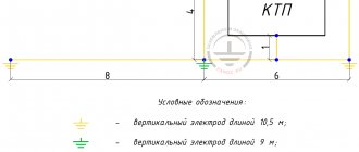
d) an artificial grounding system, consisting of three or more vertical electrodes with a length of at least 3 m, united by a horizontal electrode, with a distance between the vertical electrodes of at least 5 m. The minimum cross-sections (diameters) of the electrodes are determined according to table. 3.
Table 2.
| Ground electrode | Sketch | Dimensions, m |
| Reinforced concrete footrest | a≥1.8 b≥0.4 l≥2.2 | |
| Reinforced concrete pile | d = 0.25-0.4 l≥5 | |
| Steel two-rod: – strip measuring 40x4 mm – rods with a diameter of d=10-20 mm | t≥0.5 l = 3-5 c = 3-5 | |
| Steel three-rod: – strip measuring 40x4 mm – rods with a diameter d = 10-20 mm | t≥0.5 l = 3-5 c = 5-6 |
Table 3.
| Shape of down conductor and grounding conductor | Cross-section (diameter) of the down conductor and grounding conductor laid | |
| outside the building in the air | in the ground | |
| Round down conductors and jumpers with diameter, mm | 6 | – |
| Round vertical electrodes with diameter, mm | – | 10 |
| Round horizontal* electrodes with diameter, mm | – | 10 |
| Rectangular electrodes: | ||
| – cross-section, mm | 48 | 160 |
| – thickness, mm | 4 | 4 |
| * Only for equalizing potentials inside buildings and for laying external contours at the bottom of the pit around the perimeter of the building. | ||
2.3. The smallest permissible air distance Sb from the protected object to the support (down conductor) of a rod or cable lightning rod (see Fig. 1 and 2) is determined depending on the height of the building, the design of the ground electrode and the equivalent electrical resistivity of the soil r, Ohm•m.
For buildings and structures with a height of no more than 30 m, the smallest permissible distance Sв, m, is equal to:
- at ρ < 100 Ohm•m for a ground electrode of any design given in clause 2.2, Sв = 3 m;
- at 100 < ρ ≤1000 Ohm•m: for grounding conductors consisting of one reinforced concrete pile, one reinforced concrete footing or a recessed reinforced concrete support post, the length of which is specified in clause 2.2a, b, Sв = 3+ l0-2 (ρ-100 );
- for ground electrodes consisting of four reinforced concrete piles or footings located in the corners of a rectangle at a distance of 3-8 m from one another, or a reinforced concrete foundation of any shape with a surface area of contact with the ground of at least 70 m2 or artificial earth electrodes specified in clause 2.2 g, Sв= 4 m.
For buildings and structures of greater height, the value of Sb defined above must be increased by 1 m for every 10 m of object height above 30 m.
2.4. The smallest permissible distance Sв from the protected object to the cable in the middle of the span (Fig. 2) is determined depending on the design of the ground electrode, the equivalent soil resistivity ρ, Ohm•m, and the total length l of lightning rods and down conductors.
With a length l < 200 m, the smallest permissible distance Sв1, m, is equal to:
- at ρ < 100 Ohm•m for a ground electrode of any design given in clause 2.2, Sв1=3.5 m;
- at 100 < ρ ≤ 1000 Ohm•m: for grounding conductors consisting of one reinforced concrete pile, one reinforced concrete footing or a recessed reinforced concrete support post, the length of which is specified in clause 2.2a, b, Sв = 3.5+3×10⁻³ (ρ-100);
- for grounding conductors consisting of four reinforced concrete piles or footings located at a distance of 3-8 m from one another, or artificial grounding conductors specified in clause 2.2d, Sв1 = 4 m.
With the total length of lightning rods and down conductors l = 200-300 m, the smallest permissible distance Sв1 should be increased by 2 m compared to the values defined above.
2.5. To prevent the introduction of high potential into the protected building or structure through underground metal communications (including through electrical cables for any purpose), grounding conductors for protection against direct lightning strikes should be, if possible, removed from these communications at the maximum distances allowed by technological requirements. The smallest permissible distances Sз, (see Fig. 1 and 2) in the ground between ground electrodes for protection against direct lightning strikes and communications introduced into buildings and structures of category 1 should be Sз = Sв + 2 (m), with Sв according to paragraph. 2.3.
2.6. If there are direct gas and breathing pipes on buildings and structures for the free removal of gases, vapors and suspensions of explosive concentrations into the atmosphere, the protection zone of lightning rods should include the space above the edge of the pipes, limited by a hemisphere with a radius of 5 m.
For gas outlet and breathing pipes equipped with caps or “goosenecks”, the lightning rod protection zone should include the space above the edge of the pipes, limited by a cylinder of height H and radius R:
- for gases heavier than air at an excess pressure inside the installation of less than 5.05 kPa (0.05 at) H = 1 m, R = 2 m; 5.05-25.25 kPa (0.05-0.25 at) H = 2.5 m, R = 5 m,
- for gases lighter than air at excess pressure inside the installation: up to 25.25 kPa H = 2.5 m, R = 5 m;
- over 25.25 kPa H= 5 m, R = 5 m.
It is not necessary to include the space above the edge of pipes in the lightning rod protection zone: when gases of non-explosive concentration are released; presence of nitrogen respiration; with constantly burning torches and torches ignited at the moment of gas release; for exhaust ventilation shafts, safety and emergency valves, the release of gases of explosive concentrations from which is carried out only in emergency cases.
2.7. To protect against secondary manifestations of lightning, the following measures must be taken:
a) metal structures and housings of all equipment and apparatus located in the protected building must be connected to the grounding device of electrical installations specified in clause 1.7, or to the reinforced concrete foundation of the building (taking into account the requirements of clause 1.8). The minimum permissible distances in the ground between this grounding conductor and the grounding conductors for protection against direct lightning strikes must be in accordance with clause 2.5;
b) inside buildings and structures between pipelines and other extended metal structures in places where they come closer to each other at a distance of less than 10 cm, every 20 m jumpers made of steel wire with a diameter of at least 5 mm or steel tape with a cross-section of at least 24 mm2 should be welded or soldered, for cables with metal sheaths or armor, jumpers must be made of flexible copper conductor in accordance with the instructions of SNiP 3.05.06-85;
c) in connections of pipeline elements or other extended metal objects, transition resistances of no more than 0.03 Ohm per contact must be provided. If it is impossible to ensure contact with the specified transition resistance using bolted connections, it is necessary to install steel jumpers, the dimensions of which are indicated in subparagraph “b”.
2.8. Protection against the introduction of high potential through underground metal communications (pipelines, cables in outer metal sheaths or pipes) should be carried out by connecting them at the entrance to the building or structure to the reinforcement of its reinforced concrete foundation, and if it is impossible to use the latter as a grounding conductor, to an artificial grounding conductor, specified in clause 2.2.
2.9. Protection against the introduction of high potential through external ground (aboveground) metal communications must be carried out by grounding them at the entrance to the building or structure and at the two communications supports closest to this entry. Reinforced concrete foundations of the building or structure and each of the supports should be used as grounding conductors, and if such use is not possible (see clause 1.8), artificial grounding conductors should be used, in accordance with clause 2.2d.
2.10. The building's entry into overhead power lines with voltages up to 1 kV, telephone, radio, and alarm networks must be carried out only with cables of at least 50 m in length with metal armor or sheath or cables laid in metal pipes.
At the entrance to the building, metal pipes, armor and cable sheaths, including those with an insulating coating of the metal shell (for example, ААШв, ААШп), must be connected to the reinforced concrete foundation of the building or (see clause 1.8) to an artificial ground electrode specified in paragraph .2.2g.
At the point where the overhead power line transitions into the cable, the metal armor and sheath of the cable, as well as the pins or hooks of the overhead line insulators must be connected to the ground electrode specified in clause 2.2d. The pins or hooks of insulators on the support of the overhead power line closest to the point of transition into the cable must be connected to the same grounding conductor.
In addition, at the point where the overhead power line passes into the cable, closed air spark gaps 2-3 mm long must be provided between each core of the cable and grounded elements, or a low-voltage valve-type arrester, for example RVN-0.5, must be installed.
Protection against the introduction of high potentials through overhead power lines with voltages above 1 kV introduced into substations located in the protected building (in-house or attached) must be carried out in accordance with the PUE.
Rules for grounding pipelines
Grounding of pipelines is a mandatory measure, enshrined in the PUE. This is how you can increase the safety of their operation, because static electricity accumulates in pipe systems, plus there is always the possibility of lightning striking the pipes. The requirements of the rules for the construction of electrical installations are to provide grounding not only for external pipelines, but also for internal ones (technological and communication).
The PUE clearly regulates how pipelines should be grounded.
- Firstly, the pipe system must be a single continuous network connected into a single circuit.
- Secondly, pipelines must be connected to the grounding system at at least two points.
As for the first position, this does not mean that the pipeline system itself must be continuous. Here it will be enough to ensure the connection of sections or individual pipelines into one single network, for which so-called wafer jumpers are most often used. In fact, this is an ordinary copper wire of the brand either PVZ or PuGV. Fastening of jumpers to the pipeline is ensured by welding, bolting, or a grounding clamp for pipes is installed.
As for the second position, experts recommend not to scatter along the entire line of the technological chain, just to make a connection at the beginning and end of the circuit.
Active and passive lightning protection
Different types of external lightning protection are a system consisting of conductive structures, some of which are installed in the upper part of objects. They intercept a lightning bolt and then release its high energy into the ground. The effect of such protection depends on the number of components and the coverage density of the hazardous area, and on the architectural features of a particular building. All processes here occur naturally, therefore such standard systems represent passive lightning protection.
Typically, it includes the following components:
- Lightning rod. Attracts to itself and receives electrostatic atmospheric discharge. Structurally, the design options come in the form of metal rods, cables stretched between supports or a receiving mesh with a set cell pitch. The latter option is used mainly on flat roofs with large areas.
- Down conductors. They seem to play a secondary role, but without them it is completely impossible to remove high currents that enter the lightning rod. They are made of thick steel wire with a diameter of 8 mm or more. This cross-section ensures the safe passage of large potentials within a short period of time.
- Grounding and lightning protection. They are used together and consist of individual grounding electrodes or an entire system that combines several electrodes into a single grounding loop. Down conductors can be connected to an existing grounding, but for this you will need to connect special arresters to the circuit.
Active protection is determined by GOST and differs significantly from passive protection, primarily by the presence of an active lightning rod, which is not a rod, but a special electronic device with the ability to be self-activated immediately before the onset of a thunderstorm. Static electricity fields generated during thunderstorms affect the receiver head and cause high voltage surges. Under their influence, reverse ionization is created in the surrounding airspace, causing the effect of attracting electrical discharges.
The active component is mounted on a metal rod that is at least 1 meter higher than the highest point of the building. All other components are installed and work almost identically, as with passive protection.
Lightning protection mesh - types, components, installation stages, some nuances
Not a single building, even a one-story building located in a densely built-up area, is insured against lightning strikes.
A lightning protection mesh installed on the roof will help protect a private home from a terrible natural phenomenon. Installation of the protective device can be done independently.
But to do this you will need to familiarize yourself with some technical nuances.
What types of lightning protection meshes are there?
The protective system is assembled from hot-dip galvanized steel rods with a diameter of at least 6 mm (optimally 8 mm).
It has the shape of a grid with square cells with a maximum side size of 5 to 20 m.
The specific indicator is determined according to regulatory documentation, depending on the category and class of lightning protection.
The grids are located:
- on top of the roof deck - a more rational option in terms of fire safety, ease of installation and replacement of rods;
- under the roofing pie - it is allowed to be performed only on flat roofs, provided that non-flammable thermal insulation and waterproofing materials are used.
The lightning protection mesh is laid in such a way that its rods in no case extend beyond the roof deck.
There is no need to fear that the appearance of the roof will suffer from the presence of such a structure.
A huge selection of components in sizes, shapes and colors will allow lightning protection to harmoniously fit into the exterior of the house.
The system consists of several elements:
- steel rods for mesh;
- holders - plastic or metal;
- down conductors;
- cross-shaped bolt clamps.
You can purchase all components in construction supermarkets, markets or online stores.
Stages of installing lightning protection
The lightning protection mesh can be installed independently, without the participation of professional roofers. The installation process includes six main steps:
- studying the grid layout;
- selection of diameter and length of steel rods;
- determining the location of down conductors and lightning rods (if necessary);
- selection of holders and clamps according to shape, material and quantity;
- installation of the mesh in place;
- performing grounding.
On pitched roofs, metal rods are placed around the perimeter of the roof, as well as along the ridge. Large areas are divided into identical rectangular cells according to standard sizes.
The holders are installed in increments of one meter. Their function is to raise the mesh above the level of the roof deck by approximately 100mm.
Standard and ridge holders are available for sale.
Their use ensures the convenience and speed of installation of the lightning protection mesh, and also allows you to eliminate the associated welding work.
A huge range of holders includes products designed for different types of roofing materials.
Types of material (profiles)
According to the requirements of the PUE, which contain instructions on what the resistance of current flow in the ground should be, in most cases this indicator is set at a level of no more than 4 ohms. To obtain this value, you usually have to make a lot of effort to adhere to the same technology requirements.
First of all, this concerns the materials used in assembling the grounding loop, selected based on the following conditions:
- When choosing pins, preference should be given to ferrous metal blanks;
- The most commonly used rod is a standard size of 16-20 mm or a corner with parameters 50x50x5 mm and a metal thickness of about 5 mm;
- It is not allowed to use reinforcement as circuit elements, since it has a hardened surface that affects the normal flow of current;
- For these purposes, it is pure rod that is suitable, and not its reinforcement substitute.
Note! For areas with dry summers, thick-walled metal pipes are best suited, the lower end of which is flattened into a cone, and then several holes are drilled in this part of the pipe. According to the provisions of the PUE, before placing them in the ground, holes of the required length are first drilled, since driving them manually is quite problematic
In the case of a particularly dry summer and a sharp deterioration in the parameters of the ground electrode, a concentrated saline solution is poured into the hollow parts of the pipes, which makes it possible to obtain the resistance that should be in accordance with the requirements of the PUE. The length of pipe blanks is selected within 2.5-3 meters, which is quite enough for most Russian regions
According to the provisions of the PUE, before placing them in the ground, holes of the required length are first drilled, since driving them in manually is quite problematic. In the case of a particularly dry summer and a sharp deterioration in the parameters of the ground electrode, a concentrated saline solution is poured into the hollow parts of the pipes, which makes it possible to obtain the resistance that should be in accordance with the requirements of the PUE. The length of pipe blanks is selected within 2.5-3 meters, which is quite enough for most Russian regions.
This type of profile blanks has special requirements regarding the order of their placement in the soil and consists of the following:
- Firstly, the pipe elements of the protective circuit must be placed at a depth exceeding the soil freezing level by at least 80-100 cm;
- Secondly, in particularly dry areas, approximately a third of the length of the ground electrode should reach wet soil layers;
- Thirdly, when fulfilling the second condition, one should focus on the peculiarities of the location of the so-called “groundwater” in a given region. If they are located at a significant depth, according to the rule formulated in the provisions of the PUE, it will be necessary to prepare longer pipe sections.
The type and profile of the pin blanks used in the construction of the grounding switch can be found in the figure below.
In practice, in most regions of Russia, a steel corner and a strip of the same metal are usually used. In order to obtain more accurate parameters of the grounding elements used, geological survey data will be required. If this information is available, it will be possible to involve specialists in calculating the parameters of the ground electrode.
What is metal bonding made of?
The elements connecting the pins (metal bond) are usually made of the following electrical materials:
- A typical copper busbar with a cross-section of less than 10 mm2;
- Aluminum strip with a cross section of about 16 mm2;
- Steel strip 100 mm2 (standard size – 25x5 mm).
Classic metal ties are usually made in the form of steel strips cut to size and welded to the corners or heads of the rod.
Important! The quality of the welding joint determines whether this grounding device or circuit can pass verification tests for compliance of the contact resistance with the standardized value (4 Ohms)
When using more expensive aluminum (copper) strips, a bolt of a suitable size is attached to them for welding, on which the supply busbars are subsequently fixed
The main thing you need to pay attention to when arranging any connections is the reliability of the resulting contact
To do this, before preparing the bolted joint, it is necessary to thoroughly clean both parts to be connected until the shine of clean metal appears. Additionally, it is advisable to sand these places, and after tightening the bolt, tighten it well, which will ensure more reliable contact.
Grounding and lightning protection
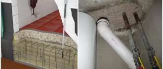
On the left is a polymer support for an air-termination mesh made of flammable material , on the right is a concrete support for fastening an air-termination mesh made of non-flammable material with a clamp for the down conductor of the lightning-prevention mesh made of hot-dip galvanized steel ( conductor fastening block BKP-4B manufactured by Elmashprom LLC). Some manufacturers of polymer conductor holders for attaching lightning protection mesh on roofs have begun to refer to the new GOST R IEC 62561.4-2014 COMPONENTS OF LIGHTNING PROTECTION SYSTEMS. PART 4. REQUIREMENTS FOR CONDUCTOR FASTENING DEVICES :
“Conductor fastening devices are classified as follows:
a) depending on the material:
— metal (for example, hot-dip galvanized steel, copper, aluminum, stainless steel).
— non-metallic (for example, PVC plastic),
— composite (a combination of metal and plastic); .."
These manufacturers sell polymer products without evidence with a letter of refusal (It simply states that these products are not subject to mandatory certification in the Russian Federation. That’s all).
The designer seems to be obliged to blindly trust this manufacturer and include its polymer products (conductor holders) in the project for attaching the lightning protection mesh based on the refusal letter and the above paragraph of this GOST.
It should be noted that in addition to refusal letters in the Russian Federation and the specified GOST, there are regulatory documents that define the primary basic requirements for these products.
The specified polymer products with a set of certain characteristics must comply with them:
The designer, not the manufacturer, bears responsibility (including criminal liability) for the project and the consequences of using products that do not comply with the requirements of the regulatory document:
Clause 2.11 (RD 34.21.122-87) directly states that the lightning protection mesh must be made of steel wire with a diameter of at least 6 mm and laid on the roof on top or under fireproof or fire-resistant insulation or waterproofing , and in clause 6 - protection from the thermal effects of a direct lightning strike is carried out by properly selecting the cross-sections of lightning rods and down conductors.
Those. fulfillment of the requirements of this regulatory document is the direct responsibility of the designer (and not the “manufacturer”).
What does a designer need from a reputable manufacturer (to prove the compliance of the applied technical solution with the regulatory document):
Written evidence that polymer products are made of fireproof or difficult to burn materials, i.e. “manufacturers of polymer products for lightning protection” must clearly present a fire safety certificate for their products and a certification test report for it, and not hide behind refusal letters. And if this certificate specifies a polymer fireproof (!?) or hard-to-burn material, you can use a polymer holder, but if the polymer material is flammable, it’s definitely not possible .
In addition, from a reputable manufacturer, this technical solution should be accompanied by a calculation for the thermal stability of this product at different lightning currents (different current strengths, and, accordingly, different degrees of heating of the conductor)
Those. in other words, a decent manufacturer is obliged to prove the product’s compliance with this regulatory document, if possible, and not with GOST.
Yes, GOST allows the use of fasteners made of non-metallic materials.
But with all this, polymer products must have the necessary proven properties for their use as fasteners
During the testing process, products are examined for compliance with a number of requirements. The certification test report reflects the degree of compliance and other characteristics of the products, including
— Release of toxic substances per unit mass of product during combustion; — Flame propagation group; — Flammability group; — Flammability group — Linear speed of flame propagation — Oxygen consumption per unit mass of the product during combustion, etc.
Reasons for providing the manufacturer of polymer conductor holders with these documents to the designer:
1. Federal Law of the Russian Federation dated December 30, 2009 N 384-FZ “Technical Regulations on the Safety of Buildings and Structures” , which states that “... the relevant Russian national standards and codes of practice become mandatory, including requirements for engineering protection - a complex of structures aimed at protecting people, a building or structure, the territory on which the construction, reconstruction and operation of a building or structure will be carried out, from the effects of hazardous natural processes and phenomena and (or) man-made impacts, threats of a terrorist nature, as well as to prevent and (or) reducing the consequences of exposure to hazardous natural processes and phenomena and (or) man-made impacts, terrorist threats;"
2. RD 34.21.122-87, which states:
“..2.11. Protection against direct lightning strikes of buildings and structures of category II with a non-metallic roof must be carried out using rod or cable lightning rods that are free-standing or installed on the protected object, providing a protection zone in accordance with the requirements of Table. 1, clause 2.6 and appendices
2.11... The lightning protection mesh must be made of steel wire with a diameter of at least 6 mm and laid on the roof on top or under fireproof or non-combustible insulation or waterproofing..
…2.25. Protection against direct lightning strikes of buildings and structures classified as category III according to the lightning protection device must be carried out using one of the methods specified in clause 2.11, in compliance with the requirements of clause. 2.12 and 2.14.
6... Lightning protection grids are laid on the non-metallic roof of protected buildings and structures. However, laying nets is rational only on buildings with horizontal roofs, where any part of them is equally likely to be struck by lightning. With large roof slopes, lightning strikes are most likely near the ridge, and in these cases, laying mesh over the entire roof surface will lead to unjustified metal costs; It is more economical to install rod or cable lightning rods, the protection zone of which includes the entire facility. For this reason, in clause 2.11, laying lightning protection mesh is allowed on non-metallic roofs with a slope of no more than 1:8. Sometimes laying the mesh over the roof is inconvenient due to its structural elements (for example, the wavy surface of the covering). In these cases, it is allowed to lay the mesh under the insulation or waterproofing, provided that they are made of fireproof or fire-resistant materials and their breakdown during a lightning discharge will not lead to the roof catching fire (clause 2.11).
...Protection from the thermal effects of a direct lightning strike is carried out by properly selecting the cross-sections of lightning rods and down conductors (Table 3), the thickness of the casings of external installations (clause 2.15), melting and penetration of which cannot occur under the above parameters of lightning current, transferred charge and temperature in the channel.
MANUAL FOR “INSTRUCTIONS FOR LIGHTNING PROTECTION OF BUILDINGS AND STRUCTURES” (RD 34.21.122-87)
4. HAZARDOUS EFFECTS OF LIGHTNING
...thermal, associated with a sharp release of heat during direct contact of the lightning channel with the contents of the object and when lightning current flows through the object. The energy released in the lightning channel is determined by the transferred charge, the duration of the flash and the amplitude of the lightning current; and in 95% of cases of lightning discharges, this energy (calculated for a resistance of 1 Ohm) exceeds 5.5 J; it is two to three orders of magnitude higher than the minimum ignition energy of most gas, steam and dust-air mixtures used in industry. Consequently, in such environments, contact with the lightning channel always creates a danger of ignition (and in some cases, explosion), the same applies to cases of lightning channel penetration of the housings of explosive outdoor installations. When lightning current flows through thin conductors, there is a danger of them melting and breaking;
3. Federal Law of July 22, 2008 N 123-FZ “Technical Regulations on Fire Safety Requirements” (as amended and supplemented), which states:
Article 12. Classification of substances and materials (except for construction, textile and leather materials) according to fire hazard
1. Classification of substances and materials by fire hazard is based on their properties and ability to form dangerous fire or explosion factors.
2. Based on flammability, substances and materials are divided into the following groups:
1) non-flammable - substances and materials that are unable to burn in air. Non-flammable substances can be fire-explosive (for example, oxidizers or substances that release flammable products when interacting with water, air oxygen, or with each other);
2) low-flammability - substances and materials that can burn in air when exposed to an ignition source, but are unable to burn independently after it is removed;
3) flammable - substances and materials capable of spontaneous combustion, as well as ignite under the influence of an ignition source and burn independently after its removal.
3. Methods for testing the flammability of substances and materials are established by fire safety regulations.
4. From flammable liquids, there are groups of flammable and especially dangerous flammable liquids, the ignition of vapors of which occurs at low temperatures determined by fire safety regulations.
Share link:
Liked this:
Like
Installation of lightning protection down conductors
Any lightning protection will not work normally if there are no down conductors and their correct placement relative to each other. It is through them that the electric current leaves the receiver and, entering the ground electrode, spreads in the ground. There are regulatory documents that determine the number and material of down conductors, their optimal cross-section and distances between lines. All this data is used when drawing up lightning protection projects.
The installed down conductor must meet the following requirements:
- After a lightning strike, the current must flow to the ground in several parallel paths.
- The current flows along the shortest path. The down conductor is installed in a straight vertical position, excluding any loops and sharp turns.
- The distances from down conductors to windows and doors must ensure the required level of safety.
The number of current-carrying lines is determined primarily by the size of the building and the type of its roof. If the perimeter of the object is less than 20 meters, then one down conductor is sufficient. When using several elements, they are distributed evenly along the entire perimeter, starting from any corner.
The simplest lightning protection consists of two down conductors located in parallel and uniformly discharging large currents to the ground. They are laid in a straight line, without bends or sharp corners, to prevent sparks, which pose a serious danger. The total number of lines is calculated for each specific case, the minimum distance is 10 m. The distance from windows and doors must be at least 50 cm.
If the installation of lightning protection, in particular down conductors, is carried out directly on the walls, in this case it is necessary to follow the established rules and recommendations of specialists:
- The fire-resistant material of the walls allows conductors to be attached to their surfaces or laid from the inside.
- If the walls are not resistant to high temperatures, the down conductors are fixed to the surface in compliance with the established gaps and other safety measures.
- Laying on flammable wall materials is carried out at a distance of over 100 mm from the surface. Only contact of metal fasteners with the wall is allowed.
- Gutters cannot be used for laying down conductors.
- Directly in front of the ground, all lines are connected to each other horizontally using special belts. In height, such connections are made every 20 meters.
Lightning protection device
We found out that to protect buildings from lightning strikes, it is necessary to build a system. It is called a lightning rod and includes three parts of equal importance:
- An air terminal is a device that directly receives a lightning discharge.
- A down conductor is a system of metal linear parts that receive currents from the lightning rod and transfer them to grounding. The elements of the down conductor can be the already mentioned reinforcement bars, metal drain pipes, etc.
- Grounding electrode – a linear or closed metal circuit. It consists of vertical pins driven into the ground, connected by a rod or strip. The ground electrode is buried at least 0.5 m. The length of the pins and the distance between them are determined by calculation methods.
A lightning rod of any architectural type must include all three listed parts, otherwise there will be no point in designing the system. The differences lie in the type of components depending on the roof and building configuration.
For example, pitched roofs are protected from lightning by installing rod receivers. Lightning rods with cable receivers are installed above elongated houses. The use of these varieties somewhat spoils the architectural ensemble, but in the end it turns out to be the most economical.
Test and inspection
- Welding joints for strength. This is done visually or by tapping with a hammer.
- Bolted connections and ties. It is necessary to tighten all connections, especially those that will be in the ground or on the roof.
- Ground resistance. It is measured with a special device - an insulation resistance meter.
- The transition resistance of contacts and joints is measured with an insulation resistance meter or an ohmmeter.
- Measuring current flow resistance with an insulation resistance meter.
- Check for compliance with project documentation.
- Reliability of fastening the lightning rod and intermediate clamps.
It is recommended that before the spring-summer period, an annual visual check of the system for damage and breaks after winter icing and winds is carried out.
It is not worth saving money on protecting people from electric shock and the safety of housing and electrical appliances. The best option is a set of measures to prevent the consequences and destruction from lightning strikes.
RD 34.21.122-87 - instructions for the installation of lightning protection of buildings and structures
INSTRUCTIONS FOR LIGHTNING PROTECTION OF BUILDINGS AND STRUCTURES
RD 34.21.122-87
Moscow GNIEI im. Krzhizhanovsky, 1987
Moscow GOSENERGONADZOR 1995
See Explanation
Office for Supervision of the Electric Power Industry of Rostekhnadzor on the joint application of the “Instructions for lightning protection of buildings and structures” (RD 34.21.122-87) and “Instructions for lightning protection of buildings, structures and industrial communications” (SO 153-34.21.122-2003)
Developer State Research Energy Institute named after. G.M. Krzhizhanovsky
Instructions for the installation of lightning protection of buildings and structures. RD 34.21.122-87
The instruction establishes a set of measures and devices to ensure the safety of people (farm animals), to protect buildings, structures, equipment and materials from explosions, fires, and destruction due to lightning. The instruction is mandatory for all ministries and departments.
Intended for specialists designing buildings and structures.
PREFACE
The requirements of this Instruction are mandatory for all ministries and departments.
The instructions must be followed when developing projects for buildings and structures.
The instructions do not apply to the design and installation of lightning protection of power lines, electrical parts of power plants and substations, contact networks, radio and television antennas, telegraph, telephone and radio broadcast lines, as well as buildings and structures whose operation is associated with the use, production or storage of gunpowder and explosives.
This Instruction regulates lightning protection measures carried out during construction and does not exclude the use of additional lightning protection means inside a building or structure during reconstruction or installation of additional technological or electrical equipment.
When developing projects for buildings and structures, in addition to the requirements of the Instructions, the requirements for lightning protection of other applicable norms, rules, instructions, and state standards must be taken into account.
With the entry into force of this Instruction, the “Instructions for the design and installation of lightning protection of buildings and structures” SN 305-77 becomes invalid.
INSTRUCTIONS FOR LIGHTNING PROTECTION OF BUILDINGS AND STRUCTURES (RD 34.21.122-87)1
GENERAL PROVISIONS
1.1. In accordance with the purpose of buildings and structures, the need for lightning protection and its category, and when using rod and cable lightning rods, the type of protection zone are determined according to table. 1 depending on the average annual duration of thunderstorms at the location of the building or structure, as well as on the expected number of lightning strikes per year. A lightning protection device is mandatory if the conditions written in columns 3 and 4 of the table are simultaneously met. 1.
An assessment of the average annual duration of thunderstorms and the expected number of lightning damage to buildings or structures is carried out in accordance with Appendix 2; construction of protection zones of various types - according to Appendix 3.
___________
1 This Instruction was developed by the State Research Energy Institute named after. G.M. Krzhizhanovsky Ministry of Energy of the USSR, agreed with the State Construction Committee of the USSR (letter No. ACh-3945-8 dated July 30, 1987) and approved by the Main Technical Directorate of the Ministry of Energy of the USSR. With the entry into force of this Instruction, the “Instructions for the design and installation of lightning protection of buildings and structures” SN 305-77 becomes invalid.
Table I
| Item No. | Buildings and constructions | Location | Type of protection zone when using rod and cable lightning rods | Lightning protection category |
| 1 | 2 | 3 | 4 | 5 |
| 1 | Buildings and structures or parts thereof, the premises of which, according to the PUE, belong to zones of classes B-I and B-II | Throughout the USSR | A | I |
| 2 | The same classes B-Ia, B-Ib, B-IIa | In areas with an average duration of thunderstorms of 10 hours per year or more | With the expected number of lightning strikes per year of a building or structure N |
Features of lightning rods for flat roofs
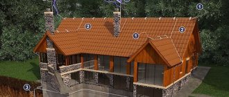
Lightning protection for houses and outbuildings with a flat roof is carried out according to a standard, practice-tested scheme:
- The lightning rod is made in the form of a mesh made of horizontally laid round steel Ø 6-8mm. Instead of wire rod, a steel strip with a cross section of 4×20mm can be used. Lightning rod as branches
- The current conductor consists of metal conductors made of round steel with a diameter of at least 6 mm connected to grounding. the underground part is made of rolled steel Ø 10mm. Pipes and fittings can serve as current drainage elements on flat roofs, if their use as a current drain was taken into account when designing the structure. The recommended distance between down conductors is 25 m.
- The grounding system is a closed loop covering the perimeter of the protected object. The distance between the ground loop and the wall of a house with a flat roof is no more than 1 m.
The lightning rod of a flat roof can be a metal roof connected to a metal sheathing or directly to down conductors using a metal connection. For such schemes, only metal roofs connected by seams are suitable. In such cases, there is no reason to install a protective mesh, but this is a completely different, “integumentary” story.
Profiled sheets with a protective coating and metal tiles are excluded from the list of possible options due to the lack of connections sufficient for the passage of currents, as well as due to the polymer shell affecting the properties of the material.
Details about mesh shock receivers
The installation of a mesh lightning rod can be carried out during the construction process or a protective system can be installed after laying the covering.
Option No. 1 is possible if non-flammable insulation, waterproofing and coating are used. The mesh is placed under the waterproof layer. The implementation scheme for a lightning rod of this type is developed at the design stage.
Option No. 2 is used without restrictions. Its design has virtually no effect on the appearance of the house. The mesh is laid on top of the coating and fixed in holders specially designed for it. In the case of constructing lightning protection for a soft roof, the holders provide a distance gap of 10-12 cm between the flammable material and the lightning rod conductor.
The first scheme predetermines the installation of a protective mesh over the floor slabs before laying the roof. To connect the branches of the mesh with the reinforcement of walls or columns, connecting devices are installed in the seams between the roof slabs, to which the mesh is welded on one side and the reinforcement on the other. In the construction of a lightning rod system of this type, only welding is used.
The second scheme involves installing receiver elements on top of the roof. She also needs a basic design to provide for the possibility of cleaning winter precipitation and the unimpeded flow of rainwater. Metal elements of the system must be protected from corrosion.
It is recommended to install lightning rods with mesh receivers on roofs with a slope of 4º to the internal or external drainage. Often, mesh systems are combined with rod counterparts, which are mounted in the corners of the building and at the intersection of conductors.
Rules for the construction of lightning protection mesh
We admit that most home craftsmen will probably have problems implementing the first option. After all, reliable welded joints must flawlessly connect the mesh with the reinforcement of the walls and foundation.
Quite high demands are placed on their quality and timeliness. Let's look at the rules for constructing the second option of lightning protection on a flat roof, which we can handle with our own hands.
General rules for installing lightning protection mesh:
- The lightning rod branches are laid perpendicularly, forming cells with equal sides.
- In accordance with the IEC (International Electrotechnical Commission) regulations, the spacing between mesh branches above residential buildings should not exceed 12 m, above garages with fuel storage up to 5 m. Domestic requirements are somewhat softer: 15m and 7m. However, it is advisable to adhere to international standards.
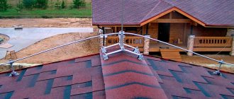
- All devices that rise above the level must be equipped with additional rod receivers. These are pipes and antenna masts that should be connected to the general network.
- Welded connections are given priority, but bolted analogues are also allowed. Especially if universal die clamps are used for their installation, which significantly facilitate installation procedures.
- It is recommended to connect the branches of the mesh receiver to the down conductor on each side.
More stringent IEC regulations dictate that each grid cross connection be equipped with rod receivers. The height of the rod requires 25 cm. Down conductors are required to be grounded with two grounding rods and detachable ram contacts are installed on them for testing operations. There is no doubt that it is time to get used to international norms, but our financial capabilities often come into conflict with them.
Domestic standards numbered RD34.21.122-87 do not make such draconian claims, and systems built in accordance with them have not yet failed. It is possible that our lightning rod, which is not too sophisticated, works well for us due to the moderate lightning load. It is still better for residents of the southern regions of the country to focus on international standards.
Let us remember that in the range of coverings for a flat roof there are flammable and non-flammable materials. Let's classify them according to combustible characteristics and analyze the most common schemes.
Lightning protection mesh on a fireproof base
The category of fireproof bases includes concrete screed, galvanized roofing sheeting, sandwich panels and gravel backfill used as ballast in inversion roofing systems.
Depending on the type of fireproof base, the installation scheme for the lightning protection mesh is selected:
- For profiled sheets that do not have a polymer coating, laying is done across the direction of the corrugation. The metal rod is laid with a planned step and welded to the surface of the corrugated sheeting wave every meter. An excellent alternative to welding are metal bolt holders, which allow installation of a mesh receiver of any degree of complexity.
- On concrete roofs, according to the design data, plastic holders with concrete filling - weighting material - are installed. Filling weight from 12 to 17 kg depending on the brand of product. The impressive weight of the products guarantees the stability of the system and resistance to gusty winds. There are holders on sale without weight filling, for installation of which a load of frost-resistant concrete is poured independently on site. For low-rise buildings in regions with low wind activity, holders are produced with fastening with self-tapping screws or gluing to bitumen mastic.
- Holders with and without concrete ballast are installed along the gravel backfill If you want to fix the holders to the base, they are mounted before adding ballast. In such cases, it is recommended to use spacer models glued to the base using mastic.
The maximum installation step of holders should not exceed 1 m for all listed schemes.
It is not recommended to install a lightning rod with a mesh conductor on metal roofs made of material thinner than 4 mm. A direct blow to the coating can easily burn through it.
Therefore, it is customary to equip roofs made of thin corrugated sheets with mesh on remote holders, the protection zone of which is still larger than that of devices in contact with the roof.
Mesh receiver on a combustible base
These include roofing coverings of the low-flammability category and materials that support combustion, because materials that are unquestionably flammable are not used in construction. The list of flat roof coatings that are hazardous according to combustion criteria includes bitumen and bitumen-polymer waterproofing materials and polymer membranes - i.e. soft roofs.
In order to prevent direct contact of the lightning discharge receiver with the bitumen and polymer coating, so-called distance holders are used. The essence of the design of simple devices is that an air gap is created between the roof surface and the mesh branch, sufficient to attenuate a possible spark.
According to the requirements of SO 153 3.2.2.4. this distance should be at least 10cm. IEC requirements indicate the need to use insulation coefficients of materials indicated by the letters km in calculations.
Insulation gaps are created using vertical rods included in the spacer holder kit. They are fixed in a plastic stand on which a concrete weighting agent is placed. The task of fastening the wire is solved by the bushing that completes the fastening device.
Algorithm for installing a lightning protection mesh with remote holders on a soft roof:
- We mark out the work site according to the developed project. The holders are installed every 1 m along the lines corresponding to the grid cells. The maximum distance between devices is 1.2 m, the possibility of increasing is specified in the manufacturer’s instructions. The design development must take into account that the areas for connecting branches to down conductors and down conductors to grounding should be minimal. Do not forget that the function of a branch can be performed by a metal parapet shield and similar long metal parts.
- Rods made of fiberglass are cut or chopped to a pre-calculated amount required to form an air insulating gap.
- According to the markings, we install plastic stands, the center of which must coincide with the marked point. In the case of a polymer membrane roof, we place a rubber gasket under each stand so that heavy parts do not damage the coating.
- We place concrete weights on the supports.
- We freely place the cut rods in the channels located in the center of the stands.
- The tops of the rods are equipped with fastening devices with bushings designed to fix wires up to Ø 8 mm.
- We lay the branches of the lightning protection mesh, simply snapping them into the bushings of the holders.
Pipes and antenna masts protruding above the surface must have an electrical connection with the lightning rod. They are equipped with rod receivers or metal aprons and connected to down conductors with die clamps. Similarly, the edges of the branches are joined to the down conductors, which is much more convenient than welding. In addition, an inexperienced performer will be able to create high-quality units with their help at a high pace.
Connection of down conductors with grid branches
Assembling a mesh discharge receiver is only the first stage of a lightning protection device and a full-fledged grounding system. It must be properly connected to the grounding circuit so that the received currents flow into the ground without obstacles.
Rules for laying and connecting down conductors:
- Down conductor routes must be designed taking into account the shortest distance between the connection points to the lightning rod and grounding.
- Down conductors are attached to flammable walls using spacer brackets. The distance between the wall and the conductor is at least 10cm. Contact between the metal bracket and the wall material is allowed.
- Down conductors can be fixed to drain pipes with metal clamps.
- It is allowed to lay down conductors made of galvanized round steel directly on a brick or concrete wall.
- The distance between the fastening points for horizontal sections is 1 m, for vertical sections is 2 m.
- Laying to form loops is not allowed.
- When choosing a location for laying a down conductor, it is recommended to select areas of the building with the least likelihood of people being present.
It is customary to lay down conductor routes in the corners of houses being developed. The maximum distance between them is 25m. The lower edge of each down conductor is lowered into the ground, where it is attached to the grounding system using a bolt device. It is recommended to wrap the areas where the conductor enters the soil with anti-corrosion tape.
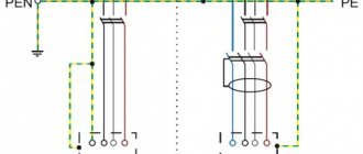
1.1.29
For color and digital designation of individual insulated or non-insulated conductors, colors and numbers must be used in accordance with GOST R 50462 “Identification of conductors by colors or digital designations”.
Protective grounding conductors in all electrical installations, as well as neutral protective conductors in electrical installations with voltages up to 1 kV with a solidly grounded neutral, incl. tires must have the letter designation PE and color designation with alternating longitudinal or transverse stripes of the same width (for tires from 15 to 100 mm) of yellow and green colors.
Zero working (neutral) conductors are designated by the letter N and the color blue. Combined neutral protective and neutral working conductors must have the letter designation PEN and a color designation: blue along the entire length and yellow-green stripes at the ends.
Lightning protection grounding device
Grounding loops are located at a distance of at least 1 meter from the object itself, paths and other places where people frequently appear. This requirement allows us to avoid the step voltage that arises during the process of spreading the charge over the ground.
If the facility has a massive reinforced concrete foundation, the grounding should be located even further, and lightning arresters should be installed inside the building to protect electronic equipment. This requirement is mandatory, since part of the lightning charge falls on the foundation and other elements in contact with it - utility networks, equipment housings.
The main indicator of grounding is its resistance. If two separate circuits are used, they are connected to each other by steel conductors by welding. The circuit resistance should be minimal so that the current can easily flow to the ground. If the soil resistivity is 500 Ohms, then the standard resistance of the ground electrode will be 10 Ohms. At higher soil resistances, the following formula is used for calculations: Rз = 10 + 0.0022 (ρ – 500) Ohm, where Rз is the resistance of the ground electrode, ρ is the soil resistivity indicator.
Standard values can be obtained by replacing the soil. The old soil is removed, and soil with other parameters and characteristics is placed in a hole or trench. After this, grounding is installed in the renewed soil. In another case, chemical reagents are added to the soil that can change its performance in the desired direction.
Once the grounding is established, regular measurements of its resistance are subsequently carried out. If its performance is outside the standard range, you should install an additional pin or replace the inappropriate element
Particular attention is paid to the connections between all components of the grounding device
Application of the TN-C system
This grounding system was and remains the most widespread in the country. With such a system, the transformer neutral is grounded at the substation. The neutral conductor is connected to the grounded neutral at the substation. In this case, the neutral conductor performs the functions of working and protective conductors and is called a PEN conductor.
Electrical installations are powered by two wires for single-phase power or four wires for three-phase power. When using the TN-C system, there is no grounding contact in electrical sockets, and the housings of all industrial electrical appliances and electrical installations in production are grounded.
The disadvantage of the system is the threat of electric shock if the neutral conductor breaks. The advantage is inexpensive electrical installation. According to the rules for electrical installations, the TN-C system was replaced by other, safer systems - TN-S and TN-CS.
What is lightning protection of buildings and structures
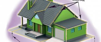
Briefly, this is a set of actions and measures, as well as various protective devices to prevent accidents and fires in buildings and structures for residential and industrial purposes when they are struck by lightning.
Lightning protection measures are divided into external and internal. External protection consists of devices that intercept the electric charge from lightning and direct it to the ground through special down conductor channels. Such structures, mounted in accordance with the mandatory technical rules for lightning protection, reliably protect buildings and people inside them from damage.
External lightning protection measures for buildings and structures are divided into active and passive.
Passive protection is presented in the following options
lightning protection mesh made of steel rods or wire rods, its use is permitted by all lightning protection standards, although at small excesses the mesh is not able to protect the roof surface reliably;
Spatial grid on the roof of a building
- metal rods (from one to several pieces) for receiving lightning discharges, a special cable connects them and grounding circuits - lightning rods;
- lightning-receiving metal cables.
All external lightning protection devices have the same standard and consist of three main parts: an electrical discharge interceptor from a thundercloud - a lightning rod; a structural part that conducts electricity to the grounding conductors, and a grounding element that discharges the lightning charge into the soil.
The internal set of lightning protection measures is aimed at preventing damage that may occur to electrical equipment from a sudden surge in voltage in the network as a result of a lightning strike. The design of internal lightning protection is presented in two types: 1 – resistance to a direct lightning strike, 2 – resistance to an indirect strike passing near buildings/structures.
The secondary impact of a lightning discharge in the form of high potentials inside buildings is combated with the help of proper grounding. Electromagnetic induction in long iron structures is removed by installing metal jumpers. The introduction of high electrical potentials through communication inputs is prevented by valve-type arresters and special spark breakers, which are triggered by a sudden voltage surge.
Valve arrester RVN 0.5
The problem is also solved by prohibiting the entry of overhead lines for certain categories of structures and replacing them with underground cable entries.
Prerequisites for the construction of lightning protection
We rarely hear about real facts of destruction of residential buildings and commercial buildings as a result of lightning strikes. True, this is not a reason to relax and neglect measures to protect against natural negativity.
Each impact poses a serious threat to homestead owners and their pets, even if specific impacts are not initially detected.
The following may be damaged by lightning strikes:
- People and animals. A discharge penetrating into a building through air communication wires can affect a living organism. It causes sparking at the connection points and connection points of devices powered by electricity. If the home does not have a grounding system or grounded metal piping, currents can pass through the body. The consequences are extremely dangerous.
- Residential and commercial buildings. Especially buildings whose walls are made of flammable material - wood. For concrete and brick houses, lightning current discharges are also very undesirable. From the point of impact to the grounded object or ground, high pressure is generated along with temperature. This area is susceptible to internal damage. There are cases where brick and wooden walls, which previously withstood several thunderstorms, split when struck by lightning.
- Private garages and small fuel depots. A lightning discharge is accompanied by a sharp increase in the temperature of a kind of branched or linear channel through which currents flow. Contact of the channel with flammable products will definitely lead to ignition and fire.
Lightning currents do not threaten metal conductors with a cross-section of 35 mm² or more. They are not dangerous for metal structures, the parts of which are reliably connected to each other by a metal bond and the lower elements are grounded.
For example, a metal sheathing is connected by welding to the reinforcement of reinforced concrete walls, and it, in turn, is connected to the foundation reinforcement. The roof elements receive the discharge, distribute it and forward it to the reinforcing bars of the walls. The currents are then transferred to the foundation reinforcement, which releases them into the ground with relief.
In addition to foundation reinforcement, lightning discharges can be transmitted to the ground by metal pipelines and cables in metal sleeves laid in the ground.
By what criteria are lightning protection levels divided?
Lightning poses a great danger to any object. Its impact can cause significant damage to both property and people staying in the structure. That is why ensuring the safety of the building becomes an important condition.
Depending on the purpose of the object and its characteristics, the levels of lightning protection are determined.
Currently there are three categories. In accordance with the Rules for the Construction of Electrical Installations (PUE), the fire resistance factor of the structure and the class of zones of indoor and outdoor buildings become an important condition. Also, one of the categories is applied depending on the likelihood of being struck by a thunderstorm.
Lightning protection 1, 2, 3 categories
Thus, category 1 lightning protection is used in the case of industrial structures with explosive zones (premises) belonging to classes B-I and B-II. In this case, the location of the object and the intensity of the impact of the thunderstorm do not matter. A type of building protection zone is provided by intercepting a direct lightning strike on its way to the structure.
In this case, the lightning protection device involves the installation of separate rod or cable outlets. The characteristic features are as follows:
- impulse resistance should not exceed 10 Ohms;
- protection against electrostatic induction is provided by installing a ground electrode;
- additionally, metal jumpers are installed by welding or soldering;
- the grounding resistance should also not exceed 10 Ohms;
- underground laying of communications and their grounding eliminates the introduction of high potentials.
Lightning protection category 2 is used for production facilities. These include classes B-Ia, B-I6 and B-IIa. Such a system is installed in areas where lightning has an average duration of 10 hours per year or more. The communication device is carried out in two ways - with separate lightning rods or by applying a special mesh to the roof, which should not be made of metal. At the same time, lightning protection of a cottage, house or any other object involves:
- resistance no more than 10 ohms;
- combining grounding elements for protection against atmospheric electricity with electrical installation devices;
- use of metal structures.
Lightning protection category 3 is to ensure the safety of objects of classes P-I, P-II, P-IIa, which are located in areas where the average duration of exposure to thunderstorms is 20 hours per year or more. In this case, the device is performed, as in the situation with the 2nd category. The only difference is that the pulse resistance should not exceed 20 Ohms. In the case of towers, pipes and derricks made of metal - 50 Ohms.
All categories of lightning protection of buildings and structures require compliance with established norms and standards. This is a guarantee not only of uninterrupted operation, but also of maximum safety.
Why should you turn to professionals?
Installation of such a system requires a careful and responsible approach. Any inaccuracies or errors can lead to disastrous consequences. Lightning protection of categories 1, 2, 3, performed by qualified specialists, is a guarantee:
- long and uninterrupted operation;
- maximum level of security;
- reliability;
- affordable cost;
- completing the task in a short time;
- professional determination of the level of lightning protection;
- prompt and competent installation of the system.
Finding an alternative solution and maximum quality are the main advantages of turning to specialists.
Lightning protection category II
2.11. Protection against direct lightning strikes of buildings and structures of category II with a non-metallic roof must be carried out by free-standing or installed on the protected object by rod or cable lightning rods, providing a protection zone in accordance with the requirements of Table. 1, clause 2.6 and appendix 3. When installing lightning rods at a facility, at least two down conductors must be provided from each rod lightning rod or each rack of a cable lightning rod. If the roof slope is no more than 1:8, a lightning protection mesh can also be used, subject to the mandatory compliance with the requirements of clause 2.6.
The lightning protection mesh must be made of steel wire with a diameter of at least 6 mm and laid on the roof on top or under fireproof or fire-resistant insulation or waterproofing. The pitch of the mesh cells should be no more than 6x6 m. The mesh nodes should be connected by welding. Metal elements protruding above the roof (pipes, shafts, ventilation devices) must be connected to the lightning protection mesh, and protruding non-metallic elements must be equipped with additional lightning rods, also connected to the lightning protection mesh.
The installation of lightning rods or the application of lightning protection mesh is not required for buildings and structures with metal trusses, provided that their roofs use fireproof or fire-resistant insulation and waterproofing.
On buildings and structures with a metal roof, the roof itself should be used as a lightning rod. In this case, all protruding non-metallic elements must be equipped with lightning rods connected to the metal of the roof, c. the requirements of clause 2.6 are also met.
Down conductors from a metal roof or lightning protection mesh must be laid to grounding conductors at least every 25 m around the perimeter of the building.
2.12. When laying lightning protection mesh and installing lightning rods on the protected object, wherever possible, metal structures of buildings and structures (columns, trusses, frames, fire escapes, etc., as well as reinforcement of reinforced concrete structures) should be used as down conductors, provided that continuous electrical connection in connections of structures and fittings with lightning rods and grounding conductors, usually performed by welding.
Down conductors laid on the outer walls of buildings should be located no closer than 3 m from the entrances or in places inaccessible to people.
2.13. In all possible cases (see clause 1.8), reinforced concrete foundations of buildings and structures should be used as grounding conductors for protection against direct lightning strikes.
If it is impossible to use foundations, artificial grounding systems are provided:
- in the presence of rod and cable lightning rods, each down conductor is connected to a grounding conductor that meets the requirements of clause 2.2d;
- if there is a lightning protection mesh or metal roof, an external contour of the following design is laid around the perimeter of the building or structure: in soils with an equivalent resistivity ρ ≤ 500 Ohm•m and a building area of more than 250 m2, a contour of horizontal electrodes is laid in the ground at a depth of at least 0 .5 m, and if the building area is less than 250 m2, one vertical or horizontal beam electrode 2-3 m long is welded to this circuit at the points where down conductors are connected;
- in soils with a resistivity of 500 < ρ ≤ 1000 Ohm•m, with a building area of more than 900 m2, it is sufficient to make a circuit of only horizontal electrodes, and with a building area of less than 900 m2, at least two vertical or horizontal beam electrodes are welded to this circuit at the points where the down conductors are connected 2-3 m long at a distance of 3-5 m from one another.
The minimum permissible cross-sections (diameters) of artificial grounding electrodes are determined according to table. 3.
In large buildings, an external ground loop can also be used to equalize the potential inside the building in accordance with the requirements of clause 1.9.
In all possible cases, the ground electrode for protection against direct lightning strikes must be combined with the ground electrode of electrical installations in accordance with the instructions in clause 1.7.
2.14. When installing free-standing lightning rods, the distance from them in the air and in the ground to the protected object and the underground utilities introduced into it is not standardized.
2.15. Outdoor installations containing flammable and liquefied gases and flammable liquids should be protected from direct lightning strikes as follows:
a) buildings of installations made of reinforced concrete, metal cases of installations and individual tanks with a roof metal thickness of less than 4 mm must be equipped with lightning rods installed on the protected object or free-standing;
b) metal casings of installations and individual tanks with a roof metal thickness of 4 mm or more, as well as individual tanks with a capacity of less than 200 m3, regardless of the thickness of the roof metal, as well as metal casings of thermally insulated installations, are sufficient to be connected to a grounding electrode.
2.16. For tank farms containing liquefied gases with a total capacity of more than 8,000 m3, as well as for tank farms with metal and reinforced concrete buildings containing flammable gases and flammable liquids, with a total capacity of a group of tanks of more than 100 thousand m3, protection against direct lightning strikes should be provided, As a rule, it is carried out with separate lightning rods.
2.17. Treatment facilities are subject to protection from direct lightning strikes if the flash point of the product contained in the wastewater exceeds its operating temperature by less than 10 °C. The protection zone of lightning rods should include a space whose base extends beyond the treatment plant by 5 m in each direction from its walls, and the height is equal to the height of the structure plus 3 m.
2.18. If there are gas outlet or breathing pipes in outdoor installations or in tanks (above or underground) containing flammable gases or flammable liquids, then they and the space above them (see clause 2.6) must be protected from direct lightning strikes. The same space is protected above the cut of the neck of the tanks into which the product is openly poured on the unloading rack. Breathing valves and the space above them, limited by a cylinder 2.5 m high with a radius of 5 m, are also subject to protection from direct lightning strikes.
For tanks with floating roofs or pontoons and the lightning rod protection zone should include a space limited by a surface, any point of which is 5 m away from the flammable liquid in the annular gap.
2.19. For outdoor installations listed in paragraphs. 2.15-2.18, in the weaving of grounding conductors for protection against direct lightning strikes, whenever possible, you should use reinforced concrete foundations of these installations or (supports of free-standing lightning rods, or make artificial grounding conductors consisting of one vertical or horizontal electrode with a length of at least 5 m.
These grounding conductors, located at least 50 m apart along the perimeter of the installation base, must be connected to the housings of external installations or down conductors of lightning rods installed on them, the number of connections is at least two.
2.20. To protect buildings and structures from secondary manifestations of lightning, the following measures must be taken:
a) metal casings of all equipment and devices installed in the protected building (structure) must be connected to the grounding device of electrical installations that complies with the instructions of clause 1.7, or to the reinforced concrete foundation of the building (taking into account the requirements of clause 1.8);
b) inside the building between pipelines and other extended metal structures in places where they come together at a distance of less than 10 cm, jumpers must be made every 30 m in accordance with the instructions of clause 2.76;
c) in flanged connections of pipelines inside the building, normal tightening of at least four bolts per flange should be ensured.
2.21. To protect outdoor installations from secondary manifestations of lightning, the metal casings of the devices installed on them must be connected to the grounding device of electrical equipment or to the grounding electrode for protection against direct lightning strikes.
On tanks with floating roofs or pontoons, it is necessary to install at least two flexible steel jumpers between the floating roofs or pontoons and the metal body of the tank or down conductors of lightning rods installed on the tank.
2.22. Protection against the introduction of high potential through underground communications is carried out by connecting them at the entrance to the building or structure to the grounding conductor of electrical installations or protection from direct lightning strikes.
2.23. Protection against the introduction of high potential through external ground (overground) communications is carried out by connecting them at the entrance to the building or structure to the ground electrode of electrical installations or protection from direct lightning strikes, and at the communication support closest to the entrance - to its reinforced concrete foundation. If it is impossible to use a foundation (see clause 1.8), an artificial grounding system must be installed, consisting of one vertical or horizontal electrode with a length of at least 5 m.
2.24. Protection against the introduction of high potential through overhead power lines, telephone, radio and alarm networks must be carried out in accordance with clause 2.10.
ELECTRIC CARS
7.4.15. In fire hazardous areas of any class, electrical machines with voltage classes up to 10 kV can be used, provided that their shells have a degree of protection in accordance with GOST 17494-72* that is not less than that indicated in table. 7.4.1.
In fire hazardous areas of any class, electric machines can be used, blown with clean air with ventilation in a closed or open cycle. When ventilation is in a closed cycle, the ventilation system must have a device to compensate for air losses and create excess pressure in machines and air ducts.
It is allowed to change the degree of protection of the shell against water penetration (2nd digit of the designation) depending on the environmental conditions in which the machines are installed.
Until the electrical industry masters large synchronous machines, direct current machines and static converter units in an enclosure with a degree of protection IP44, it is allowed to use machines and units with a degree of enclosure protection of at least IP20 in fire hazardous areas of class P-IIa.
7.4.16. Air for ventilation of electrical machines must not contain vapors and dust of flammable substances. The release of exhaust air with an open ventilation cycle into a fire hazardous area is not allowed.