What is a protective conductor (PE)?
A protective conductor (PE), according to GOST 30331.1-2013 [1], is a conductor intended for electrical safety purposes, for example, for protection against electric shock. It is not a conductive conductor and should never be energized under normal conditions. People use jargon - “grounding wire”, “zero protective conductor”, which is incorrect. In national regulatory and legal documentation covering low-voltage electrical installations, the term “PE conductor” is sometimes used instead of the term “protective conductor”.
Kharechko Yu.V. in his book [2] explains why the term “protective conductor” should be used and not the term “neutral protective conductor”:
“In the vast majority of cases, when implementing measures to protect against electric shock in electrical installations of buildings, special conductors are used, which in regulatory documentation are called protective conductors. The protective conductor connected to the grounded current-carrying part of the power source, for example to the grounded neutral of a transformer, is called the neutral protective conductor in national regulations. However, this name should be excluded from use, since neither the IEA nor the IEC standards and other documents contain such a term. »
[2]
Application
In my opinion, Yu.V. Kharechko wrote most succinctly about the use of protective conductors. in his book [2]:
“Protective conductors are used in low-voltage electrical systems of both alternating and direct current, as well as in electrical installations of buildings that are part of these systems. »
[2]
The following are specific examples of the use of protective conductors in various systems.
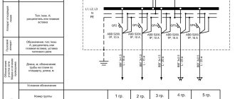
In TN-S AC and DC systems, as, for example, shown in Figures 1A and 1B, respectively, the protective conductors “start” from the grounded live parts of the power supplies.
Rice. 1A. TN-S three-phase four-wire system with separated neutral conductor and protective conductor throughout the entire system (based on Figure 31A1 from GOST 30331.1-2013)
Rice. 1B. TN-S DC three-wire system (based on Figure 31H from GOST 30331.1-2013)
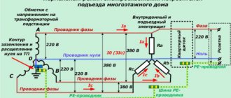
In TN-CS AC systems, as for example shown in Figure 2A, the protective conductors “start” from the points where the PEN conductors separate into protective and neutral conductors. In TN-CS AC systems, protective conductors can also “start” from the points of separation of PEL conductors into protective and phase conductors (see Figure 2B.
In TN-CS DC systems, as shown in Figure 2B, the protective conductors “start” at the points where the PEL conductor is divided into protective and pole conductors and the PEM conductor into protective and middle conductors.
Rice. 2A. TN-CS three-phase four-wire system, in which the PEN conductor is divided into a protective conductor PE and a neutral conductor N somewhere in the electrical installation (based on Figure 31B1 from GOST 30331.1-2013)
Rice. 2B. TN-CS single-phase two-wire system with separation of the PEL conductor into a grounded linear conductor and a protective conductor for part of the electrical installation (based on Figure 2 from the book [2] Kharechko Yu.V.)
Rice. 2B. TN-CS DC three-wire system (based on Figure 31K from GOST 30331.1-2013)
In TT (Figures 3A and 3B) and IT systems of alternating and direct current (Figure 4), the protective conductors “start” from the grounding devices of low-voltage electrical installations.
Rice. 3A. TT system three-phase four-wire with a grounded protective conductor and a neutral conductor throughout the system (based on Figure 31F1 from GOST 30331.1-2013)
Rice. 3B. Three-wire DC TT system (based on Figure 31L from GOST 30331.1-2013)
Rice. 4. Three-wire DC IT system (based on Figure 31M from GOST 30331.1-2013)
How to choose the correct cross-section of the grounding cable?
Before choosing the size of the wiring cross-section, you need to decide on the type of protective system.
Similar: Frequency of checking power tools
According to the PEU, the following options are accepted for use:
- the neutral cable is connected to the ground electrode when using alternating current;
- combining the neutral cable and ground together, neutral wiring is connected separately;
- connecting electrical equipment directly to the main ground bus;
- creating a ground connection on the body of an electrical device using a resistance or by insulating all cables.
When choosing a cable, you need to be guided by the marking, in which PE means “grounding”, and “ground” and “zero” are indicated by the PEN marking when connected in one wire.
When selecting the size of the wire cross-section, it is necessary to take into account the type of grounding itself, which can be portable or stationary. In everyday life, a stationary type of protective device is usually used. With this scheme, devices can be connected to the grounding conductor with multi-core and single-core cables. When choosing suitable conductive cores when creating protective systems, you need to use the recommended diameter sizes of the wiring used.
Examples of protective conductors and their purpose
Examples of protective conductors, according to GOST R 50571.5.54-2013 [3], include: a protective potential equalization conductor, used to perform protective potential equalization, a protective grounding conductor, which is used to perform protective grounding. Protective conductors are also PEN, PEM and PEL conductors, which, firstly, perform the functions of protective grounding conductors and, secondly, neutral, medium and linear conductors.
Let us turn to the book [2], the author of which is Yu.V. Kharechko describes in more detail the purpose of various protective conductors:
“By means of protective conductors, PEN-, PEM- and PEL-conductors in the TN-C, TN-S and TN-CS systems, the exposed conductive parts of class I electrical equipment used in electrical installations of buildings are connected to grounded current-carrying parts of power supplies. Since any of these conductors must be grounded at the entrance to the electrical installation of the building, with the help of protective conductors, PEN, PEM and PEL conductors, the exposed conductive parts of class I electrical equipment are connected to the grounding devices of electrical installations of buildings. By means of protective conductors in electrical installations of buildings corresponding to the grounding types of the TT and IT systems, exposed conductive parts of electrical equipment of class I are connected to the grounding devices of electrical installations of buildings. »
[2]
“By means of protective potential equalization conductors in buildings, third-party conductive parts are electrically connected to each other and connected to the grounding devices of electrical installations of buildings. When performing additional potential equalization, protective potential equalization conductors connect exposed conductive parts of class I electrical equipment with third-party conductive parts in building areas that are characterized by increased danger, for example, have conductive floors. »
[2]
Figure 5 shows a schematic illustration of the types of protective conductors used in the electrical installation of a building, and the main types of conductive parts to which the protective conductors are connected.
Rice. 5. Grounding and protective conductors (based on Figure 8 from the book [2] Kharechko Yu.V.)
In Figure 5 the following symbols:
- 1 – protective conductor;
- 2 – main conductor of potential equalization;
- 3 – grounding conductor;
- 4 – conductor of additional potential equalization;
- B – main grounding clamp;
- M – open conductive part;
- C – third-party conductive part;
- P – metal water pipe;
- T – ground electrode.
Figure 6 shows the arrangement of protective conductors in more detail (this diagram is taken from GOST R 50571.5.54-2013).
Rice. 6. Examples of a grounding device, foundation grounding electrodes, protective conductors and protective potential equalization conductors (based on Figure B.54.1 from [4])
In Figure 6 the following symbols:
- C – third-party conductive part;
- C1 – water pipe, metal on the outside;
- C2 – sewer pipe, metal on the outside;
- C3 – gas pipe with an insulating insert, metal on the outside;
- C4 – air conditioning;
- C5 – heating system;
- C6 – metal water pipe (for example, in a bathroom);
- C7 – metal sewer pipe (for example, in a bathroom);
- D – insulating insert;
- NRU – low-voltage switchgear;
- GZZ – main grounding clamp;
- SEBT – terminal for additional potential equalization;
- T1 – foundation grounding electrode embedded in concrete or soil;
- T2 – grounding electrode for the lightning protection system, if necessary;
- LPS – lightning protection system, if available;
- PE – protective terminal(s) in low voltage switchgear;
- PE/PEN – protective or PEN terminal(s) in the main low-voltage switchgear;
- M – open conductive part;
- 1 – protective grounding conductor (PE);
- 1a – protective conductor or PEN conductor from the supply network, if available;
- 2 – protective potential equalization conductor for connection to the main grounding terminal;
- 3 – protective conductor of additional potential equalization;
- 4 – lightning protection system (LPS) down conductor, if available;
- 5 – grounding conductor.
PEN conductor separation
Why split the PEN conductor? According to PUE-7
7.1.13. Electrical receivers must be powered from a 380/220 V network with a TN-S or TN-C-S grounding system. When reconstructing residential and public buildings with a network voltage of 220/127 V or 3 x 220 V, it is necessary to provide for transferring the network to a voltage of 380/220 V with a TN-S or TN-C-S grounding system.
We already know that in many houses the electrical wiring is made according to outdated standards with a TN-C grounding system, and in order to transfer the network to TN-S or TN-C-S it is necessary to divide the PEN into zero working and zero protective conductors.
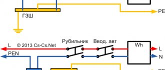
Rules for separating PEN conductor
1. The separation of the PEN conductor is carried out in the input distribution device.
Splitting a PEN wire in a floor panel is a gross violation of the existing house power supply design. You cannot interfere with the existing scheme!
2. From the point where PEN is divided into N and PE conductors, their further connection is prohibited.
3. After separation, the tires are considered different and are marked accordingly:
- N - blue.
- PE - yellow-green.
4. Between the PE and N busbars there must be a jumper with a cross-section no smaller than the busbars themselves.
Important! Grounding is always placed first and a jumper goes from it to the working zero.
5. The PE conductor bus must be grounded and in contact with the transformer body.
6. Bus N is installed on insulators - it should not be in contact with the housing.
Why do you need a jumper between PE and N buses?
The jumper is required for the input circuit breaker to operate. If there is no jumper and the phase hits the equipment body, the current will go to the ground and not to the transformer.
If we take the average value of the resistance of the grounding chain to be 20 ohms, the leakage current will not be enough to trip the circuit breaker. The circuit will continue to function until the damaged section burns out or a full short circuit occurs. This situation may result in electric shock, equipment damage and fire.
In this case, an RCD - a residual current device - will help, but you should not rely on it alone; two-factor protection will be required - without it, the connection will not be accepted by energy supervision. It is recommended to install an RCD in any case.
Requirements
Since protective conductors are used as part of protection measures against electric shock, regulatory and legal documents impose special requirements on their characteristics, design and technical condition.
Yu.V. Kharechko writes about the basic requirements for protective conductors. in his book [2]:
“One of the main requirements for protective conductors is to ensure the continuity of their electrical circuits. GOST R 50571.5.54-2013 (clause 543.3.3) prohibited the inclusion of switching devices in the electrical circuits of protective conductors. An exception is sockets and plugs, through which portable, mobile and other electrical equipment of class I with a detachable connection are connected to stationary electrical wiring. The electrical circuits of protective conductors in detachable connections are broken along with the electrical circuits of phase conductors and the neutral conductor, pole conductors and the middle conductor. »
[2]
However, the requirements of GOST R 50571.5.54-2013 [3] allow the presence of detachable connections in the circuits of protective conductors, which can be disassembled using a tool to carry out the necessary tests. Connections of protective conductors shall be accessible for inspection and testing, with the exception of connections filled with compound or sealed.
“Protective conductors must be adequately protected from mechanical, chemical and electrochemical damage, as well as from electrodynamic forces that occur when overcurrents flow in electrical circuits. »
[2]
Particular attention should be paid to the correct connection of plug sockets with a cable, since this may result in sequential inclusion of their protective contacts in the electrical circuit of the protective conductor.
Kharechko Yu.V. in his dictionary [2] explains this “case” in more detail:
“Modern two-pole plug sockets used in single-phase electrical circuits usually have two spring clamps designed to connect the phase, neutral and protective conductors. When the protective conductor of the electrical wiring is connected to the first terminal of the protective contact of the first socket, the conductor of the first terminal of the protective contact of the second socket is connected to the second terminal of the protective contact of the first, the first terminal of the protective contact of the third socket to the second terminal of the second protective contact, etc. will have place for sequential connection of the protective contacts of plug sockets into the protective conductor. In the case of connecting plug sockets with a cable, the connection of their protective contacts must be made to the branches from the protective conductor of the stationary electrical wiring, which are usually carried out in installation boxes. »
[2]
Important facts [2,3]:
- In electrical installations, it is prohibited to use a protective conductor for signal transmission (GOST R 58698—2019).
- It is not necessary to connect each individual protective conductor directly to the main earth terminal (bus) if they are electrically connected to it through other protective conductors.
- Exposed conductive parts of electrical equipment must be connected to a terminal designed for the protective conductor.
- If overcurrent protection devices are used to protect against electric shock as part of an automatic power shutdown, protective conductors made of single-core wires should be laid in a common sheath with linear conductors or in close proximity to them.
The following conductive parts can be used as protective conductors [2]:
- cores of multicore wires and cables;
- insulated or non-insulated single-core wires;
- metal cable sheaths;
- metal pipes, shells and electrical boxes in which conductors of some electrical wiring are located, if they have sufficient conductivity and the continuity of their electrical circuits is ensured;
- some third-party conductive parts, if they have sufficient conductivity, the continuity of their electrical circuits and protection from dismantling are ensured;
- shells and frames of class I low-voltage switchgear and busbar trunking, if they have sufficient conductivity, the continuity of their electrical circuits is ensured, as well as the possibility of connecting other protective conductors in any designated place.
Clause 543.2.3 of the current standard GOST R 50571.5.54-2013 [3] lists conductive parts that are prohibited from being used as protective conductors and protective potential equalization conductors:
– metal water pipes; – metal pipes containing potentially flammable substances such as gases, liquids, dust; – structures subject to mechanical loads during normal operation; – flexible or soft metal pipes, with the exception of those specifically intended for these purposes; – flexible metal parts; – support structures for wires, horizontal and vertical cable trays.
Kharechko Yu.V. in his book [2] he adds:
“As established by GOST R 50571.5.54-2013 [3], open conductive parts of one electrical equipment, with the exception of switchgears and busbars, are not allowed to be used as protective conductors for other electrical equipment. It is prohibited to sequentially connect open conductive parts of class I electrical equipment into the protective conductor. The connection of each open conductive part of class I electrical equipment should be made with a separate protective conductor, which is formed, for example, as a branch from the protective conductor of stationary electrical wiring in a pull-out, branch or installation box. »
[2]
Color and letter identification
Protective conductors must be identified by a two-color yellow-green combination, according to GOST 33542-2015 [5]. The alphanumeric identification of the protective conductor shall be "PE". This identification is also used for the protective earth conductor.
The combination of yellow and green colors is only intended to identify the protective conductor.
Rice. 7. Alphanumeric designation of conductors for three-phase electrical installations in buildings
According to clause 6.3.2 of GOST 33542-2015:
“The yellow-green color combination shall be such that for any 15 mm of conductor length where a color designation is used, one of these colors covers not less than 30% and not more than 70% of the surface of the conductor, and the other color covers the remainder of this surface.
If bare protective conductors are supplied painted, they shall be painted yellow-green either along the entire length of each conductor, or in each compartment or block, or in each accessible location. If adhesive tape is used for color identification, use only two-color yellow/green tape. »
[5]
“Where a protective conductor can be easily identified by its shape, design or position, for example a concentric conductor, it is permissible not to color-code its entire length, but the ends and accessible locations should be identified by a graphic designation (see figure
or yellow-green two-color combination, or alphanumeric designation “PE.”
[5]
“If third-party conductive parts are used as a protective conductor, it is permissible not to identify them by colors. »
[5]
Rice.
8. Identification of protective conductor Important to know! According to clause 6.1 of GOST 33542-2015, identification by colors or marks is not required for:
- metal sheaths or armor of cables when they are used as a protective conductor;
- third-party conductive parts used as a protective conductor; exposed conductive parts used as a protective conductor.
Connection
Before connecting, it is necessary to mark the main terminals of five or three-wire wires. If you are just doing installation work, you will be able to independently determine which wire to connect where, otherwise you will have to understand the existing wiring. In practice, to determine the location of all types of wires in the connection diagram, use their color designation:
- Phase conductors - have a wide variety of spectrum (brown, red, gray, purple, etc.);
- Grounding conductors are made in yellow-green color, some manufacturers use only bright green color;
- Neutral conductor – blue or cyan.
However, note that not all installers follow the standard marking procedure or the wire itself may not correspond to the power supply diagram, so before using a ground or phase wire, it is worth ringing them first.
The connection itself is made in such a way as to ensure the most reliable contact with zero or close to it transition resistance. Therefore, the most acceptable is soldering, crimping or tightening under a nut or tip.
It is strictly forbidden to make an electrical connection to the grounding wire by twisting or other non-standard methods. If a copper and aluminum conductor are connected, a brass gasket must be installed between them or they are crimped into a sleeve. Next, the grounding wire is connected from the circuit to the equipment body, metal elements to equalize the potential, or to the corresponding socket contact.
Section
The cross-section of the protective conductor is selected according to table 54.2 from GOST R 50571.5.54-2013 [3]:
Minimum cross-sectional area of protective conductors (when not calculated in accordance with 543.1.2 GOST R 50571.5.54-2013/IEC 60364-5-54: 2011)
| Section of copper linear conductors S, mm2 | Minimum cross-section of the corresponding protective conductor made, mm2 | ||
| made of copper | from other metals | ||
| S ≤ 16 | S | (k1/k2)*S | |
| 16 < S ≤ 35 | 161) | (k1/k2)*16 | |
| S>35 | S/21) | (k1/k2)*(S/2) | |
| k1 is the value of coefficient k for a linear conductor, calculated according to the formula of Appendix A.54.1 of GOST R 50571.5.54 or taken from table 43A of GOST R 50571.4.43-2012 in accordance with the material of the conductor and insulation. If the conductor material is copper, then k1 = 226, if aluminum, then k1 = 148, if steel, then k1 = 78. k2 - the value of the k coefficient for the protective conductor, selected from tables A.54.2-A.54.6 GOST R 50571.5.54 in accordance with the conditions of use. | |||
| 1) For a PEN conductor, reducing the cross-section is possible only if the restrictions on the selection of the cross-section of the neutral conductor are met (see GOST R 50571.5.52-2011/IEC 60364-5-52:2009) | |||
Or calculated in accordance with paragraph 543.1.2 of GOST R 50571.5.54-2013. The cross-section of protective conductors must be no less than [3,4]:
- cross-section selected in accordance with the instructions of IEC 60949;
- or cross-section calculated using the following formula, is used only when the overcurrent shutdown time is not more than 5 s.
Where
- S—section, mm2;
- I is the rms value of the expected earth fault current for a fault with negligible impedance that can flow through the protective device (see IEC 60909-0), A;
- t is the time the protective device switches off the ground fault current (fault current), s;
- k is a coefficient depending on the material of the protective conductor, insulation, adjacent parts, initial and final temperatures.
Coefficient k in this case should be selected according to tables A.54.2-A.54.6 [3], or calculated using the following formula:
- Qc is the volumetric heat capacity of the conductor material at 20 °C, J/°C mm3;
- β is the reciprocal of the temperature coefficient of conductor resistivity at 0 °C, °C;
- ρ20—electrical resistivity of the conductor material at 20 °C, Ohm mm;
- θf—final conductor temperature, °C;
- θi is the initial temperature of the conductor, °C.
| Conductor material | β, °C | Qc , J/°C mm3 | ρ20, Ohm mm |
| Copper | 234,5 | 3,45·10-3 | 17,241·10-6 |
| Aluminum | 228 | 2,5·10-3 | 28,264·10-6 |
| Steel | 202 | 3,8·10-3 | 138·10-6 |
Parameter values for various materials (from table A.54.1 GOST R 50571.5.54-2013)
If, as a result of calculations, a non-standard cross-section is obtained, a protective conductor with the nearest larger standard cross-section should be used.
Notes for this item:
1) Current limitation due to circuit impedance and I2t limitation by the protection device must be taken into account.
2) Guidance on temperature limits in explosive atmospheres is given in IEC 60079-0.
3) For mineral insulated cables (IEC 60702-1), in the case where the short-circuit current resistance of the metal sheath of the cable is greater than that of linear conductors, it is not necessary to calculate the cross-section of the metal sheath used as a protective conductor.
Important! In accordance with paragraph 543.1.3 of GOST R 50571.5.54-2013, the cross-section of any protective conductor that is not a cable core or is not laid in a common sheath with linear conductors must be no less than:
- 2.5 mm2 (copper) or 16 mm2 (aluminum) if there is mechanical protection;
- 4 mm2 (copper) or 16 mm2 (aluminium) if there is no mechanical protection.
That is, in other words:
“In all cases where protective conductors are not part of a multi-core cable, their minimum copper cross-section should be 2.5 mm2 if mechanical protection is present and 4.0 mm2 if it is not. The cross-section of separately laid protective conductors made of aluminum must be at least 16 mm2. »
[2,3]
At the same time, a protective conductor that is not part of the cable is considered mechanically protected if it is laid in a pipe, box or other similar method.
If the protective conductor is common to two or more circuits, then its cross-section is selected as follows [3]:
- calculated in accordance with 543.1.2 GOST R 50571.5.54-2013 , based on the maximum expected ground fault current and shutdown time in these circuits;
- or selected according to table 54.2 of GOST R 50571.5.54-2013 for the largest cross-section of the linear conductor included in these circuits.
Grounding devices for electrical installations with voltages up to 1 kV in networks with a solidly grounded neutral
1.7.100. In electrical installations with a solidly grounded neutral, the neutral of a three-phase alternating current generator or transformer, the midpoint of a direct current source, one of the terminals of a single-phase current source must be connected to the grounding conductor using a grounding conductor.
An artificial ground electrode designed to ground the neutral, as a rule, should be located near the generator or transformer. For intra-shop substations, it is allowed to place the ground electrode near the wall of the building.
If the foundation of the building in which the substation is located is used as natural grounding, the neutral of the transformer should be grounded by connecting to at least two metal columns or to embedded parts welded to the reinforcement of at least two reinforced concrete foundations.
When built-in substations are located on different floors of a multi-story building, the grounding of the neutral of the transformers of such substations must be carried out using a specially laid grounding conductor. In this case, the grounding conductor must be additionally connected to the building column closest to the transformer, and its resistance is taken into account when determining the spreading resistance of the grounding device to which the transformer neutral is connected.
In all cases, measures must be taken to ensure continuity of the grounding circuit and protect the grounding conductor from mechanical damage.
If a current transformer is installed in the PEN conductor connecting the neutral of a transformer or generator to the PEN bus of a switchgear with voltage up to 1 kV, then the grounding conductor should not be connected to the neutral of the transformer or generator directly, but to the PEN conductor, if possible immediately after the transformer current In this case, the division of the PEN conductor into PE and N conductors in the TN-S system must also be carried out behind the current transformer. The current transformer should be placed as close as possible to the neutral terminal of the generator or transformer.
1.7.101. The resistance of the grounding device to which the neutrals of a generator or transformer or the terminals of a single-phase current source are connected, at any time of the year should be no more than 2, 4 and 8 Ohms, respectively, at line voltages of 660, 380 and 220 V of a three-phase current source or 380, 220 and 127 In a single-phase current source. This resistance must be ensured taking into account the use of natural grounding conductors, as well as re-grounding conductors PEN or PE conductor of an overhead line with a voltage of up to 1 kV with a number of outgoing lines of at least two. The resistance of the ground electrode located in close proximity to the neutral of the generator or transformer or the output of a single-phase current source must be no more than 15, 30 and 60 Ohms, respectively, at line voltages of 660, 380 and 220 V of a three-phase current source or 380, 220 and 127 V of a single-phase source current
If the earth resistivity r >100 Ohm×m, it is allowed to increase the specified standards by 0.01r times, but not more than tenfold.
1.7.102. At the ends of overhead lines or branches from them with a length of more than 200 m, as well as at the inputs of overhead lines to electrical installations in which automatic power off is used as a protective measure in case of indirect contact, the PEN conductor must be re-grounded. In this case, first of all, natural grounding devices should be used, for example, underground parts of supports, as well as grounding devices intended for lightning overvoltages (see Chapter 2.4).
The specified repeated groundings are performed if more frequent groundings are not required under the conditions of protection against lightning surges.
Repeated grounding of the PEN conductor in DC networks must be performed using separate artificial grounding conductors, which should not have metal connections to underground pipelines.
Grounding conductors for repeated grounding of the PEN conductor must have dimensions no less than those given in table. 1.7.4.
Table 1.7.4
The smallest dimensions of grounding conductors and grounding conductors laid in the ground
| Material | Section profile | Diameter, mm | Cross-sectional area, mm | Wall thickness, mm |
| Black steel | Round: | |||
| for vertical grounding conductors | 16 | — | — | |
| for horizontal grounding conductors | 10 | — | — | |
| Rectangular | — | 100 | 4 | |
| Angular | — | 100 | 4 | |
| Pipe | 32 | — | 3,5 | |
| Galvanized steel | Round: | |||
| for vertical grounding conductors | 12 | — | — | |
| for horizontal grounding conductors | 10 | — | — | |
| Rectangular | — | 75 | 3 | |
| Pipe | 25 | — | 2 | |
| Copper | Round | 12 | — | — |
| Rectangular | — | 50 | 2 | |
| Pipe | 20 | — | 2 | |
| Multi-wire rope | 1,8* | 35 | — |
* Diameter of each wire.
1.7.103. The total resistance to spreading of grounding conductors (including natural ones) of all repeated groundings of the PEN conductor of each power line at any time of the year should be no more than 5, 10 and 20 Ohms, respectively, at line voltages of 660, 380 and 220 V of a three-phase current source or 380, 220 and 127 V single-phase current source. In this case, the spreading resistance of the grounding conductor of each of the repeated groundings should be no more than 15, 30 and 60 Ohms, respectively, at the same voltages.
If the specific resistance of the earth is r >100 Ohm×m, it is allowed to increase the specified standards by 0.01 r times, but not more than tenfold.
Grounding devices for electrical installations with voltages up to 1 kV in networks with an insulated neutral
1.7.104. The resistance of the earthing device used for protective earthing of exposed conductive parts in an IT system must satisfy the following condition:
R ≤ Upr/I,
where R is the resistance of the grounding device, Ohm;
Upr is the touch voltage, the value of which is assumed to be 50 V (see also 1.7.53 );
I is the total ground fault current, A.
As a rule, it is not necessary to accept a grounding device resistance value of less than 4 ohms. A grounding device resistance of up to 10 Ohms is allowed if the above condition is met, and the power of generators or transformers does not exceed 100 kVA, including the total power of generators or transformers operating in parallel.
Grounding devices in areas with high earth resistivity
1.7.105. Grounding devices of electrical installations with voltages above 1 kV with an effectively grounded neutral in areas with high earth resistivity, including in permafrost areas, are recommended to comply with the requirements for touch voltage (see 1.7.91).
In rocky structures, it is allowed to lay horizontal grounding conductors at a shallower depth than required by 1.7.91-1.7.93, but not less than 0.15 m. In addition, it is allowed not to install the vertical grounding conductors required by 1.7.90 at entrances and at entrances.
1.7.106. When constructing artificial grounding systems in areas with high earth resistivity, the following measures are recommended:
1) installation of vertical grounding conductors of increased length, if the resistivity of the earth decreases with depth, and there are no natural deep grounding conductors (for example, wells with metal casing pipes);
2) installation of remote grounding electrodes, if there are places with lower earth resistivity near (up to 2 km) from the electrical installation;
3) laying moist clay soil in trenches around horizontal grounding conductors in rocky structures, followed by compaction and backfilling with crushed stone to the top of the trench;
4) the use of artificial soil treatment in order to reduce its resistivity, if other methods cannot be used or do not give the required effect.
1.7.107. In permafrost areas, in addition to the recommendations given in 1.7.106, you should:
1) place grounding conductors in non-freezing reservoirs and thawed zones;
2) use well casing pipes;
3) in addition to deep grounding conductors, use extended grounding conductors at a depth of about 0.5 m, designed to operate in the summer when the surface layer of the earth thaws;
4) create artificial thawed zones.
1.7.108. In electrical installations with voltages above 1 kV, as well as up to 1 kV with an isolated neutral for earth with a resistivity of more than 500 Ohm×m, if the measures provided for in 1.7.105-1.7.107 do not allow obtaining earthing conductors acceptable for economic reasons, it is allowed to increase the required this chapter, the values of the resistance of grounding devices are 0.002r times, where r is the equivalent resistivity of the earth, Ohm×m. In this case, the increase in the resistance of grounding devices required by this chapter should be no more than tenfold.
Grounding switches
1.7.109. The following can be used as natural grounding electrodes:
1) metal and reinforced concrete structures of buildings and structures that are in contact with the ground, including reinforced concrete foundations of buildings and structures that have protective waterproofing coatings in non-aggressive, slightly aggressive and moderately aggressive environments;
2) metal water pipes laid in the ground;
3) casing pipes of boreholes;
4) metal sheet piles of hydraulic structures, water conduits, embedded parts of valves, etc.;
5) rail tracks of main non-electrified railways and access roads if there is a deliberate arrangement of jumpers between the rails;
6) other metal structures and structures located in the ground;
7) metal shells of armored cables laid in the ground. Cable sheaths can serve as the only grounding conductors when there are at least two cables. Aluminum cable sheaths are not allowed to be used as grounding conductors.
1.7.110. It is not allowed to use pipelines of flammable liquids, flammable or explosive gases and mixtures, and sewerage and central heating pipelines as grounding conductors. The specified restrictions do not exclude the need to connect such pipelines to a grounding device for the purpose of equalizing potentials in accordance with 1.7.82.
Reinforced concrete structures of buildings and structures with prestressed reinforcement should not be used as grounding conductors, however, this restriction does not apply to overhead line supports and outdoor switchgear support structures.
The possibility of using natural grounding conductors based on the density of currents flowing through them, the need to weld reinforcing bars of reinforced concrete foundations and structures, welding anchor bolts of steel columns to reinforcing bars of reinforced concrete foundations, as well as the possibility of using foundations in highly aggressive environments must be determined by calculation.
1.7.111. Artificial grounding conductors can be made of black or galvanized steel or copper.
Artificial grounding conductors should not be painted.
The material and smallest dimensions of grounding conductors must correspond to those given in table. 1.7.4.
1.7.112. The cross-section of horizontal grounding conductors for electrical installations with voltages above 1 kV should be selected according to the condition of thermal resistance at a permissible heating temperature of 400 °C (short-term heating corresponding to the duration of the protection and tripping of the circuit breaker).
If there is a risk of corrosion of grounding devices, one of the following measures should be taken:
increase the cross-sections of grounding conductors and grounding conductors, taking into account their estimated service life;
use galvanized or copper grounding conductors and grounding conductors.
In this case, one should take into account the possible increase in the resistance of grounding devices due to corrosion.
Trenches for horizontal grounding conductors must be filled with homogeneous soil that does not contain crushed stone and construction waste.
Grounding electrodes should not be located (used) in places where the ground is dried out by the heat of pipelines, etc.
Grounding conductors
1.7.113. The cross-sections of grounding conductors in electrical installations with voltages up to 1 kV must comply with the requirements of 1.7.126 for protective conductors.
The smallest cross-sections of grounding conductors laid in the ground must correspond to those given in table. 1.7.4.
Laying bare aluminum conductors in the ground is not permitted.
1.7.116. To carry out measurements of the resistance of the grounding device, it must be possible to disconnect the grounding conductor in a convenient place. In electrical installations with voltages up to 1 kV, such a place, as a rule, is the main grounding bus. Disconnection of the grounding conductor must be possible only with the help of a tool.
1.7.117. The grounding conductor connecting the working (functional) grounding conductor to the main grounding bus in electrical installations with voltages up to 1 kV must have a cross-section of at least: copper - 10 mm2, aluminum - 16 mm2, steel - 75 mm2.
1.7.118. An identification sign must be provided at the points where grounding conductors enter buildings
1.7.126. The smallest cross-sectional areas of protective conductors must comply with table. 1.7.5.
The cross-sectional areas are given for the case when the protective conductors are made of the same material as the phase conductors. The cross-sections of protective conductors made of other materials must be equivalent in conductivity to those given.
Table 1.7.5
Smallest cross-sections of protective conductors
| Section of phase conductors, mm2 | Minimum cross-section of protective conductors, mm |
| S ≤ 16 | S |
| 16 < S ≤ 35 | 16 |
| S>35 | S/2 |
Frequently asked typical questions from readers
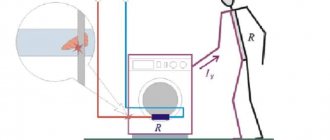
- The electrical plug on the old Soviet water pump has been cut off. All wires are the same color. How to determine where the protective conductor is?
In principle, there is nothing complicated here; to determine the protective conductor you will need the pump itself and a multimeter (tester); if you have neither a multimeter nor a tester, but have a megohmmeter, then you can use that.To check, follow these steps:
— Strip the ends of the three conductors that come out of the pump in such a way that you can clearly touch them with the probe in turn, excluding contact of the probe with adjacent conductors.
— Then set the tester to continuity testing mode, connect the probes to the corresponding terminals of the multimeter.
— Fix one dipstick on the pump body. It is important that the installation location makes good contact, so if there is paint, a thick layer of dirt and other obstacles to the flow of electric current into the housing, they need to be cleaned or a different location chosen.
— Using the second probe, as shown in the figure below, touch each of the cores of the pump power cord one by one.
— The core that shows the circuit with the body is the protective conductor. Accordingly, the other two are the phase conductor and the neutral conductor.
This method is relevant for checking a working pump; if the insulation of the windings of an electrical machine has a breakdown to the housing, then not only the PE conductor will contact the ground.
Why you can’t separate the PEN conductor in the floor panel
This option cannot be used for a number of reasons:
- If we take into account exclusively the provisions of the PUE, they state that the separation of wires should occur at the input circuit breaker of an apartment building or a private detached house.
- Even if the apartment panel is considered a water machine (which is quite problematic to do), such a connection will be incorrect according to another requirement, namely, the PE conductor must be re-grounded, which is impossible to achieve in the floor panel.
- Even if you get clever and connect the grounding to the floor panel, there is another obstacle that threatens with large fines. The fact is that the electrical circuit during the construction of a house is approved by several authorities and its unauthorized change is a gross violation of all existing rules - in fact, it is a change in the design according to which the house was connected to the network. Such matters should be handled exclusively by the organization serving this house or area.
Of course, if such an organization plans any work to separate the Pen conductor, then there is no point in messing around with each floor panel separately. The best option would be to separate it at the input machine, which is what will be done.
An additional argument in favor of separating the Pen conductor on one circuit breaker in a residential building is the requirement of the PUE (clause 7.1.87) to install a potential equalization system in this place.
It is prohibited to do it in any other place, which means that the separation of the PEN conductor in the floor panel will in any case be done without observing all the necessary rules and precautions.
As a result, the only correct method for grounding a house is a collective appeal to the organization serving the house or area.
References
- GOST 30331.1-2013
- Kharechko Yu.V. Brief terminological dictionary for low-voltage electrical installations. Part 1// Supplement to the journal “Library of a Labor Safety Engineer”. – 2011. – No. 3. – 160 p.
- GOST R 50571.5.54-2013
- Due to the fact that GOST R 50571.5.54-2013 contains many serious errors, the article was brought into line with the work of Yu.V. Kharechko journal "Energy efficiency, energy safety, energy supervision", 2015, No. 2 - "Analysis of errors in the new GOST R 50571.5.54-2013, which applies to grounding devices and protective conductors."
- GOST 33542-2015