Thermostats designed to control heating with electric heated floors have a special designation.
Do not confuse them with other popular models that are produced to work with gas boilers or water heating through a manifold.
On the back of the device between the two terminals, look for an image in the form of a snake (pins L1 and N1).
This is where the cable for a warm floor or electric mat is connected.
To the end of L1 is the central core of the cable, to N1 is the braid.
An external temperature sensor that prevents overheating of heated floors and controls heating is mounted on blocks with a sensor image (NTC).
The polarity of connecting the sensor wires is not important. Connect them in any order.
Temperature determination error
Please note that the temperature directly at the remote sensor will always be higher than the temperature in the room, which the regulator shows on its display.
This is due to the depth of the sensor in the screed.
Usually this delta, between t on the floor surface and t inside the screed, does not exceed 5-7 degrees.
On the displays of electronic devices you can see both parameters, but in mechanical devices with a wheel, degrees are often not even written around the circumference, but only the numbers 1-2-3, etc. are indicated.
With five digits, one division corresponds to approximately 8 degrees.
Degrees are not indicated for a specific purpose, so as not to confuse the user. You set the thermostat housing to +25C, but the room thermometer in the apartment will only show +20C.
Most people will immediately ask the question: why does the regulator operate with such an error? Is it broken?
No, he's fine. In this case, the sensor in the floor warms up to +25C, not the air in the room. That is why manufacturers simply indicate numbers in mechanics, so that you, focusing only on your feelings, can choose the most comfortable mode for yourself.
If degrees are indicated on your mechanical thermostat, this means that it mainly works and is guided by its own air temperature sensor built into the housing.
The one that is connected to it from the outside and hidden in the tie only plays the role of protecting the cable from overheating.
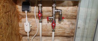
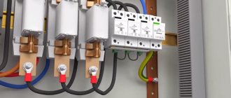
Supply 220V power to terminals L and N through an RCD with a leakage current of no more than 30mA.
The diagram for connecting a heated floor directly through a thermostat from different manufacturers is the same and looks like this.
Types of temperature sensors
The classification of thermostats according to their operating principle was considered when reviewing their advantages and disadvantages. But it’s worth learning more about how they work.
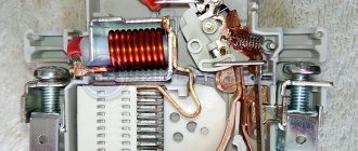
Electromechanical
The simplest and most inexpensive type of regulator. Its main working part is a special metal plate that reacts to an increase or decrease in temperature. The system is turned on and off by changing the curvature of the plate during heating and cooling. It will not be possible to set the exact temperature value on such a regulator.
Electronic
The device contains a special element that produces a special signal. Power depends directly on the ambient temperature values. On such devices, you can set precise heating temperature indicators down to a fraction of a degree. The system is controlled via buttons and a small screen.
Programmable
The most expensive of thermoelements. You can set certain values on it, upon reaching which the entire system is turned on or off by the regulator. Thanks to the device, a microclimate is created in the room that suits a specific person. It is possible to configure the thermostat so that the system turns on at a certain time. That is, the floors are heated before the owner comes home, and electricity is not consumed when the owner is away.
Many models have a bright and stylish design, and are also equipped with LCD screens that display information and facilitate precise settings.
Connection diagram for high power heated floors
When connecting, be sure to check the power that the thermostat can pass through. Usually it is designed for a load of no more than 16A (3.7 kW at a voltage of 230V).
This is exactly the maximum value. It is recommended to use the device under a constant load of no more than 70% of this power.
In this case, the device will last a long time and function properly. The switch that switches the contact quickly fails when overheated. And along with it you will have to change the entire device.
For loads greater than 3.7 kW, a modular contactor will be required.
The connection diagram in this case will change to the following.
Here, instead of the load, the wires from the regulator go to the contacts of the switching coil (A1-A2), and the heating cable itself is connected to the power terminals of the starter (1-2 or 3-4).
Phasing on the thermostat
A common question is: is there a difference where to connect the phase on the thermostat and where to connect the zero?
Yes, I have. This does not affect the operating logic of the device, but it does not affect the safety.
If you confuse the phase and zero, then when the thermostat is turned off, it will not be the phase conductor that will break, but the neutral one. Thus, the phase will be constantly present on the underfloor heating cable, which is naturally not safe.
In those devices that have a separate switch on the case, when it is pressed, two conductors are broken at once, both phase and zero. But this is in manual shutdown mode, and not in all models.
Often the zero is fed directly through its track. I went into the terminal and immediately went to the heated floor.
In this case, the switch itself is only responsible for interrupting the power supply to the control board. When automatically triggered by a sensor, only one wire is always broken.
Criterias of choice
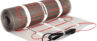
The models of manufactured warm infrared film floors have distinctive technical characteristics. When choosing a system, there are some factors to consider:
- Film quality and size. The characteristics of the product indicate the characteristics and material of the heated floor. The denser and more layers the film coating has, the higher the resistance to mechanical damage. The width of the roll is selected depending on the design features of the room and its area.
- Power. The value of this parameter is influenced by the size of the heated room and the purpose of the heated floor system itself. For equipment that is installed as the main heating, a fairly high power rating is required.
- Integrity and completeness of the system. When purchasing a heated film floor, you must visually inspect the product to ensure there is no damage. The presence of all elements included in the heating device will also be checked.
It is recommended to purchase a high-quality infrared heating system in specialized stores, where a quality certificate for the product and a guarantee of its use are provided.
Do you need land?
Also note that the protective grounding is directly to the thermostat itself at class=”aligncenter” width=”700″ height=”434″[/img]
This can be a separate, separate terminal through which the heating cable shield is connected to the protective conductor.
The thermostats themselves even have a “square within a square” icon, which means a device with double insulation.
These marks are typically found on portable tools that do not require a grounding pin on the power cord plug.
The difference between expensive electronic thermostats and mechanical ones
What super-tasks are solved by smart thermostats filled with electronics and a display? It would seem, why buy an expensive product if you can buy a regulator with a mechanical wheel and set the desired temperature for yourself in the same way?
And the point here is one of the fundamental problems of comfortable operation of heating systems - inertia.
The fact is that having set an acceptable temperature on warm floors in the region of 23-25C, after reaching it, even with the heating device turned off, the system will still continue to gain degrees by inertia up to a certain point.
The same applies to the minimum parameter. In fact, such fluctuations in a room can reach from 19 to 27C.
There is no question of maintaining comfortable conditions with such variations. In smart electronic thermostats, all this is solved by PWM regulation.
This term comes from radio electronics. There PWM is pulse width modulation. In heating, this principle consists of changing the switching time and operation of the heating elements.
While the temperature in the room is far from the desired parameters (set at +25C, in the room +18C), the heated floors are turned on all the time (heating, heating and heating).
However, as the set point is reached (+25C), heat begins to be supplied as if in small, short pulses (on-off). Due to this, the temperature is accurately maintained in a comfortable area.
In this case, you can forget about inertial processes associated with overheating or, conversely, excessive cooling. You won't get anything like this from a thermostat with a wheel.
Possible installation errors
For the proper functioning of the film heating system, perfect accuracy of installation and connection of the entire device is required. In the process of performing independent installation work, mistakes are often made. Therefore, you should know what not to do when installing such equipment:
- lay the film overlapping;
- install one thermostat on two separate circuits;
- attach the film to the base using nails or other sharp fasteners;
- install equipment near other heating devices;
- connect the device without isolating the contacts to the electrical network;
- use a material containing foil as a substrate;
- cover the system with cement mortar;
- install large pieces of furniture in places where the film passes;
- bend the material with the carbon mixture at a right angle.
To avoid damage to the film during renovation work indoors, it is recommended to maintain precise laying diagrams.
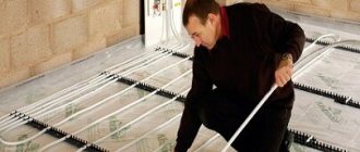
Compared to many other floor heating systems, installation of film heating equipment is much simpler. Following the diagrams and instructions provided by the manufacturer, you can install the device yourself. But connecting the system to the network requires certain professional skills. Therefore, the process of connecting all devices must be carried out by a qualified electrician.
Thermostat is not working - how to check?
At the same time, do not expect any major changes when replacing a thermostat from one model to another. There is an opinion that if the warm floor does not heat up, then it is worth changing the thermostat to a more expensive one, everything will change by itself.
The air temperature in the room will immediately rise, and where it was previously cold, it will become hot. Roughly speaking, the thermostat is like the speedometer in your car.
You can draw 300-350 km/h on the speedometer, but if the engine is not capable of producing such power, then you will not see this speed. If something is to blame for the poor performance of heated floors, then first of all look at the temperature sensor.
Checking the functionality of the thermostat is very simple. Supply it with 220V power and connect the remote sensor.
Next, instead of a warm floor, connect a regular incandescent light bulb to the thermostat. You begin to unscrew the knob, changing the temperature.
At a certain moment the light should light up.
Next, hold the temperature sensor in your hand and wait. When heat comes from your body, a working thermostat will turn on and the light bulb will go out.
If the sensor is hidden deep in the screed, you can warm up the area with a hairdryer and wait for the same effect. When the lamp does not react at all, this indicates a malfunction of the device.
The fastest way to repair in this case is to transfer the work from the floor sensor to the air sensor built into the housing.
The ends of the cable on the device from the floor temperature source will have to be unscrewed, and the settings of the device itself will have to be reset.
All this will work correctly provided that the thermostat is installed directly in the heated room.
If you have an electronic thermostat with PWM control, then using the above test method, it is not recommended to heat the sensor too quickly with an extraneous heat source. What does this mean?
Firstly, the thermostat will immediately detect an abnormal increase in heat and work ahead of time. Secondly, the “smart brains” of the device will forcibly turn off the heating for the next 20 minutes.
In this case, after just 5 minutes the temperature on the device’s display will be sufficient to turn on, and startup and contact closure will not occur. As a result, you will have doubts about the correct operation of the thermostat.
Therefore, the fast heat test is ideal for mechanical devices, but be careful with electronic ones.
Scope of application
Film equipment is widely used for heating various types of premises. The system can act as:
- additional heating device;
- main source of heat.
Also, heated floors can be installed to maintain the temperature of individual areas of the room. Film flooring is most often used for heating;
- living rooms;
- bathrooms;
- utility rooms;
- loggias;
- bathrooms;
- winter gardens;
- public buildings;
- gyms.
Often, film heating systems are used in kindergartens or playrooms. The device has gained such popularity due to numerous positive characteristics, which include safety of use.
Connecting a temperature sensor
Another error occurs when replacing or connecting sensors from different manufacturers to the same regulator. The fact is that they all have a certain resistance corresponding to a particular temperature.
And if you change the temperature sensor to another without changing the settings, this may lead to incorrect heating operation. The difference in temperature between the detected and actual temperature can reach 10 degrees!
Due to a different resistance, less than the factory one, the regulator will understand this as an excessive temperature and give a command to turn off early, although the heated floors will not yet be warm enough.
For heated floors, so-called NTC sensors are used - negative temperature coefficient sensors. This term means that as the ambient temperature increases, their resistance decreases.
There is also PTC - positive t coefficient. resistance. The reverse process occurs with them.
Advanced devices (Devireg Touch) initially have several types of sensors included in the settings program. At the installation stage, simply select the required one.
If you don't know the brand, you will have to manually measure the resistance with a multimeter.
The received data is compared and checked whether they correspond to the factory settings or not.
The most correct heating system is considered to be one that has its own control zone in each room. What does this mean?
If there is only one thermostat in the house, the temperature spread in different parts of the building will reach 5-6 degrees.
Therefore, you will have to buy and install not one, but several thermostats.
You can set separate controllers for two zones simultaneously, while changing the temperature priority. That is, install it in a thermostat in one room, and run a remote sensor from it into the next room.
In this case, in the settings you will need to select which element the thermostat should respond to - one built into the housing or an external one. You will not be able to achieve the same temperature from one device.
It is prohibited to place thermostats in wet areas. They must have an appropriate IP level of moisture protection and be installed in zone 3.
What kind of zone this is, read in a separate article.
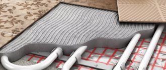
Laying infrared film and connecting heating elements
The film is carefully cut along the lines intended for this purpose to obtain pieces of the desired size. Place the thermal film towards the thermostat. You need to make sure that the copper strip is at the bottom. The film is fixed together with construction tape.
To connect the heating elements together, proceed as follows:
- the stripped tip of the wire is installed inside the contact clamps;
- a clamp with wires is attached to the heating element of the film (one end is located on the copper busbar, the other - inside the structure);
- fix with pliers;
- insulate the places where the tires are cut and where the electrical cable is connected with bitumen tape.
Advice. You need to plan the sections of infrared film so that there are a minimum of connections. The length of one strip should not be longer than 8 meters.
To prevent the joints of the heating elements from sticking out, recesses are cut out for them in the heat-insulating layer.