To connect a single-phase electricity meter, it is not necessary to call a qualified technician. If you have a connection diagram and some wiring skills, you can do this work yourself. After which you need to call a representative of the electricity supply organization to accept, seal and register the electricity meter.
Electricity meter device
Electricity meters are used to record consumed electrical energy. Electricity meters are induction and electronic.
The measuring mechanism of an induction single-phase electric energy meter (an electrical measuring device of an induction system) consists of two electromagnets located at an angle of 90° to each other, in the magnetic field of which there is a light aluminum disk. The electrical energy meter device diagram is shown in the figure.
To connect the meter to the circuit, its current winding is connected to electrical receivers in series, and the voltage winding is connected in parallel. When an alternating current induction meter passes through the windings, alternating magnetic fluxes arise in the winding cores, which, penetrating the aluminum disk, induce eddy currents in it.
The interaction of eddy currents with the magnetic fluxes of electromagnets creates a force under the influence of which the disk rotates. The latter is connected to a counting mechanism that takes into account the rotation frequency of the disk, i.e. electrical energy consumption.
- Electric energy meter device diagram:
- 1 - current winding;
- 2 - voltage winding;
- 3 - worm mechanism;
- 4 — counting mechanism;
- 5 — aluminum disk;
- b - magnet for braking the disk.
To account for consumed electricity in three-phase alternating current networks, three-phase induction electricity meters are used, the operating principle of which is similar to single-phase ones.
Currently, electronic (digital) electricity meters are becoming more and more widely used.
- Electronic meters have a number of advantages compared to induction meters:
- small overall dimensions;
- no rotating parts;
- possibility of metering electricity at several tariffs;
- measurement of daily maximum load;
- accounting of both active and reactive power;
- higher accuracy class;
- possibility of remote metering of electricity.
Some tips and safety measures
To summarize all of the above, it makes sense to summarize the basic safety measures when installing power cabinets and connecting electric meters:
- All work is carried out with the voltage removed;
- The wiring should start from the apartment or room, and the power input should be connected last;
If you clearly understand how to connect a single-phase or three-phase electric meter, no special difficulties will arise during its installation, and therefore it is quite possible to connect the electric meter yourself. And if all of the above measures are observed, the electrical wiring will continue to bring light into the apartment for a long time, and its maintenance will not cause any problems.
Commissioning or reconstruction of electrical wiring in a house or apartment is rarely complete without installing or replacing an electric meter. According to the standards, work can only be performed by specially trained people who have permission to work in networks with voltages up to 1000 V. But you can install all the elements and connect the meter to the load (electrical appliances) without connecting the power supply yourself. Afterwards, you need to call a representative of the energy supply organization to test, seal and start up the system.
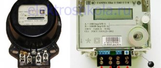
One of the housing options for the meter
How to install an electric meter in an apartment
Let's start with the installation of an input two-pole circuit breaker. Using a special latch located on the back wall of the machine, we install it on the upper DIN rail.
The next step is the installation of an electricity meter. On its back wall, just like on the machine, there is a latch for mounting on a DIN rail.
Now, we install outgoing single-pole circuit breakers. In our example, there will be two of them.
The installation of the modular equipment electricity meter is completed, let's proceed to the connection.
Rules for installing an electric meter
According to the PUE, a protective disconnecting device must be installed in front of the metering device (electricity meter). As a rule, in most cases, such a device is a two-pole circuit breaker.
- In the meter connection diagram, it performs the following functions:
- protection of the electric meter from short circuit;
- from fire due to exceeding the permissible load for which the meter is designed;
- the ability to perform work on replacement and maintenance of the meter.
Limitation of permitted power (regulated by the rating of the circuit breaker). In our example, the input protective device will be installed directly in the apartment panel, box. Also, in some cases, it can be installed in the floor panel, on the landing. Here, the main criterion is the method and possibility of filling.
Everything in the box must be sealed. If the service organization has the ability to seal the circuit breaker, then it is mounted in a box; if not, then in a floor panel.
The machine is sealed with special stickers that are glued to the contact screws, top and bottom of the circuit breaker. The meter is sealed with plastic or lead seals.
How to install a two-tariff meter
When cold weather sets in, we try to heat our homes using boilers, air conditioners and other electrical appliances. Therefore, we have to pay a tidy sum for electricity. But no one knows that the tariff for electricity at night is much lower than the tariff during the day.
The advantage of using such counters is that they are more accurate and take into account all errors than the readings of a mechanical one.
- The process of installing a two-tariff meter itself takes place in approximately 7 stages:
- It is necessary to write an application at the nearest regional energy department. To do this, prepare the following documents: a certificate from the gas office, a boiler passport, a boiler power supply project and technical specifications. You will receive a response letter to your application within some time, and maybe within a few days.
- Purchase of a multi-tariff meter. If you buy a meter in a store, you can also program it there. In the same place you should be given a protocol for parameterizing the meter. With this protocol you go to the Distribution Zone. Here you will be asked to write a new application in which you ask to check the parameterization of the meter. This body sends an electronic application to the oblenergo to check the parameterization.
- You are taking your new meter to the regional power company. There, for about half a day, they check the parameterization of the meter.
- Go back to the distribution network, find the customer service department and write an application there to replace the meter. After which, you are assigned a person who will unseal and re-seal your meter.
- After this entire procedure, you need to write an application to renew the agreement with the distribution network on the supply of electricity at new tariffs.
- After that, you pick up a new counter.
- And most importantly, don’t forget to pick up your new contract at the RES.
Installation materials
DIN rail made of aluminum
The electrical metering device is connected after selecting a circuit and purchasing materials. To connect your apartment meter correctly and efficiently, you will need:
- auto switches taking into account the maximum current rating;
- insulating devices;
- instruments with handles coated with insulation;
- fastening elements – screws and nuts;
- wires;
- din rail.
Further work is carried out according to a strict algorithm.
Connecting a single-phase electricity meter
Single-phase meters for houses and apartments are made directly connected, i.e. without additional step-down current transformers.
There is nothing complicated in connecting a single-phase meter; before installing the meter, carefully study the documentation, instructions, examples of connecting single-phase meter circuits, etc.
- To correctly connect a single-phase meter, we first of all need a single-phase meter circuit, which can be found:
- The documentation that comes with the electric meter is a passport, instructions or form for the meter, which indicates all the characteristics, serial number, dates of manufacture and verification of the meter, and of course - the circuit of the single-phase meter itself.
- Additionally, the set of documents for the meter may also include an operating manual, which will also indicate the diagram of a single-phase meter.
- Without fail, on the back of the terminal cover of any electric meter, there will be a diagram of a single-phase meter.
Having studied the diagram of a single-phase meter “on paper,” let’s turn directly to the electric meter itself.
- A simple single-phase meter has 4 contacts on the terminal block:
- terminal No. 1 – phase input from an external network (to a house or apartment);
- terminal No. 2 – phase output (inside the house or apartment);
- terminal No. 3 - zero input from an external network (to a house or apartment);
- terminal No. 4 - zero output (inside the house or apartment).
In the same sequence, we connect the wires to the contacts of our single-phase electric meter, not forgetting to turn off the machine, plugs or switch that is installed in front of the single-phase electric meter, if your input cable (wire) immediately goes to the meter, in this case, you need to turn off the line.
When replacing an old single-phase electric meter, if you decide to replace it yourself or call a friend-neighbor who is an electrician, at a minimum, make a call to your network company, management company, HOA and find out what needs to be done to replace the single-phase meter. The main question is who will tear the seal off the old meter.
If you break the seal on an old electric meter and install a new one, and only then notify the power grid, serious problems may arise. You may be accused of stealing electricity (the seal has been broken) and will be subject to a large fine.
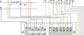
Connection diagram for a single-phase electricity meter
Scheme of a single-phase meter, when an input circuit breaker is installed in front of the meter. This should be the case according to the PUE, but if the input machine cannot be sealed, the network organization will not allow such a meter connection scheme.
Scheme of a single-phase meter, when the input circuit breaker is installed after the meter. This option for connecting an electric meter is used if it is not possible to seal the input machine. The cable (wire) is connected directly to the electric meter, the terminal cover is sealed and there is no possibility of electricity theft.
Connecting an electricity meter yourself
If we talk about a single-phase meter, then in this case only a third of the power and voltage produced directly at the electricity substation is used, so to speak. The thing is that industrial electric generators have three windings and, as a result, three phases.
A single-phase electricity meter and the entire subsequent circuit are actually connected to only one of the three phases. Which? Yes, anyone! Here, the main task for designers and those who subsequently carry out the installation is to make sure that the power consumption is evenly distributed among each phase. That is, if a neighbor has one phase, then you get another, and the third neighbor gets a third!
The connection of a single-phase electricity meter is carried out according to the diagram below. The diagram is usually shown on the back of the cover of the new meter.
The connection diagram for a single-phase electricity meter has already been unchanged for at least 40 years. Therefore, you can safely use it if you have a meter, but do not have an electrical connection diagram for it.
The following is a standard (current) connection diagram for a 220-volt meter, taken from the meter cover.
The contacts are shown in accordance with their actual location on the meter (when viewed from the front side) and the inputs and outputs to them: F - phase, 0 - zero, G - current from the generator of the electric manufacturer, that is, the input to the meter, N - load, then there is access to your apartment. 13 and 14 additional output for instrumentation (not available on all meters, used for taking control data and measurements)
Pulling contacts
Surely, if a person installed electrical wiring in an apartment on his own, he already knows that the connection contacts must be tight enough to prevent heating and failure of the wires. But it won’t hurt to remind you of this. Moreover, this rule applies primarily to the electric meter and power cabinet circuit breakers.
The contact terminals of the electricity meter have two mounting screws. First, the wire is fixed in the socket with the upper screw, then the lower one is pulled through. It is important to remember that after the power cabinet has been operating under load for one to two weeks, it is necessary to re-check the tightness of the fixing screws of the electric meter and machines. Particular attention should be paid to the zero bus and its contacts, since if the tightening is insufficient, it is the “zero” that begins to “burn.”
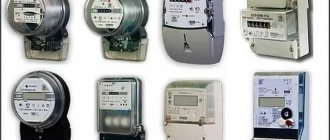
Types of electricity meters
- Electric meters are divided into the following types:
- induction;
- electronic.
An induction-type electric meter operates on the principle of a magnetic field generated by two coils: voltage and current. The magnetic field acts on the disk and causes it to rotate.
The disk, in turn, drives the counting mechanism. As the voltage and current in the network increase, the disk will rotate faster and increase the energy consumption readings.
The accuracy of such devices leaves much to be desired and is equal to 2.5. But such meters are considered one of the most reliable; it’s not for nothing that they have a 15-year warranty.
Electronic electricity meters are devices that act directly by measuring current and voltage in the network. It does not have any intermediate links or mechanisms, so there is no loss of accuracy either. The parameters are displayed on the display and stored in the meter’s memory in digital form.
- Let us list the advantages of electronic meters:
- compact dimensions;
- function of accounting at several tariffs;
- possibility of additional installation of a microcircuit to increase the accuracy class;
- accurate and quick determination of readings, since the device is equipped with a digital display;
- it is very difficult to deceive such a counter, due to the possibility of self-correction of readings;
- a standard, common interface allows the meters to be used in automatic accounting and control systems.
Among the disadvantages, it should be noted the lack of reliability in comparison with induction-type meters, as well as the increased cost.
Connecting the Mercury 201 meter
Before installing and connecting the electric meter, you need to carefully read the operating instructions, the device data sheet, and study the direct connection diagram.
- The single-phase meter on the terminal block contains 4 input contacts:
- Contact for entering a phase from an external network (220V) into an apartment or house. The input wire comes from the power supply company.
- Contact for phase exit inside an apartment or house. For the output, you can use a ShVVP type wire.
- Terminal for connecting zero from an external network to an apartment or house.
- The zero output terminal is further towards the load, that is, inside the apartment or house.
- Connecting the wires should be done in the same sequence.
Important to remember! Before connecting the meter, it is necessary to de-energize the system by turning off the machine, plugs, switch (if they are installed between the main trunk line and the meter). If the input cable goes directly to the meter, disconnect the supply line.
The connected wires are neatly laid out; for this purpose, the terminal cover has perforated cells for breaking out. The cover is screwed to fit tightly to the meter body.
You should check the connection diagram again and install the cover. Then, a representative of the network organization that provides the supply and metering of electricity seals the Mercury 201 meter. For this purpose, there is a special hole in the meter.
When the meter is connected to the mains, the red indicator light lights up.
Energy meter single-phase
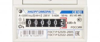
- Energy meter CE 101
The single-phase meter model Energomera CE 101 is one of the most common metering devices. This simple and reliable device with a 5-year warranty period enjoys a good reputation among users.
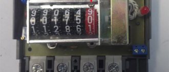
According to the principle of operation, Energomer CE 101 is an electronic device in which the measured voltage and current are multiplied using sigma-delta modulation. The signal is then converted into a value that is proportional to power. The signal is pulsed in nature, and the pulses are summed by an electromechanical type counting device or microcontroller.
The result is displayed on the rotating reels or on the LCD screen. There can be one or two current circuits. If there are two, the highest current is recorded. The Energomer ce101 meter is a modern device that has the ability to connect the meter to ASKUE (automated metering) systems or for testing operations.
Devices with LCD have a memory that does not depend on the presence of power, which allows you to save measured values when disconnected from the power supply, and a liquid crystal display with displayed information. If the display is damaged, the data can be read after connecting a working screen.
Connection to automated accounting systems is carried out using special terminals on the front part of the housing, closed with a plastic cover.
The counter CE 101 is equipped with light indicators. Some devices have two LEDs: “Network” and “A”. The lighting of one of them, with the inscription “Network”, indicates that the device is connected to the power supply. The second blinks when the load is connected.
- Other modifications of the device have one LED “3200 imp/kW*h”, operating in two modes:
- when there is no load, it lights up evenly;
- When a load appears, the LED starts blinking, the blinking frequency is proportional to the load current.
Some models have a “Robr” indicator. When it lights up, it indicates that the reverse power is counting down.
- If the Network LED is not lit, there may be two reasons:
- Due to incorrect connection of the Energomera CE 101 meter. You should check the diagram and check the reliability of the connected contacts.
- There is a malfunction in the device or in the LED itself. The device must be sent for repair.
When the “Network” indicator is on and the counting mechanism does not work, the device must also be sent for repair.
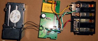
- Inside the case there are:
- a measuring module in the form of a printed circuit board that converts power into a pulse signal;
- one or two current sensors (current transformers, shunts).
The single-phase meter Energomer is connected according to a unified scheme. At the entrance to the apartment's electrical network there are two (phase neutral) or three (phase, neutral, ground) wires. First you need to choose the option of how to connect the meter using a single-pole or double-pole circuit breaker.
- Electricity meters model CE 101 are available in two installation options:
- S6 – direct installation on the panel wall;
- R5 – installation on DIN rail.
- To connect the electric meter Energomer CE 101, in accordance with the technical documentation, there are 4 contacts located at the bottom of the front panel:
- 1 – phase wire of the input cable;
- 3 – phase wire going to the load;
- 4 – “zero” wire of the input cable;
- 5 – wire “zero” load.
In documentation, these four pins are sometimes designated: 1, 2, 3, 4.
Important! If there are three wires at the entrance to the apartment’s single-phase network, the “ground” wire is not used when connecting the electric meter; it is connected to a grounding device.
When executing the circuit using a single-pole circuit breaker, only the phase wire must be connected through it, and the neutral wire must be connected directly. But the use of a two-pole device with both phase and zero inserted through it is preferable, since in emergency situations the neutral conductor may be under high voltage.
Important! If a connection diagram with a two-pole circuit breaker is used, two single-pole devices cannot be used instead.
- For installation you will need:
- depending on the modification, mounting screws, DIN rail;
- the counter itself;
- automatic switches for installation in front of the meter and for load distribution after the meter;
- copper wire for installation with a diameter of 1 to 6 mm;
- voltage indicators;
- working tools (pliers, screwdrivers, etc.).
Important! Before starting work, you must remove power from the input cable and check the absence of voltage with an indicator or multimeter.
- Step-by-step installation of the electric meter Energomera CE 101:
- Mark where the metering device and machines will be located. Counters should not be placed below 160 cm from the floor or other base, otherwise it will be inconvenient to read the information.
- Using a level, check whether the future installation is horizontal and drill the mounting holes.
- The meter is installed first, then the circuit breakers are mounted on the panel wall or DIN rail.
- The input and load cables are inserted into the panel with the meter. When installing outside buildings, sealing glands must be installed at the entry points.
- Carefully separate the wires and remove the insulating coating approximately 300 mm from their ends.
- Make wires of the required length to assemble the electrical circuit between the meter and the machines and mark them to facilitate connection to the right places.
- Before connecting the input cable, apply the supply voltage and check the location of the phase and neutral wires with an indicator. Then turn off the voltage again.
- Connect the input cable to a two-pole circuit breaker: top right - phase cable, left - neutral. If using a single-pole circuit breaker, insert a phase conductor through it.
Connection steps
Installing an electric meter
Initially, you need to calculate how many phases are in the home electrical network. The number of circuit breakers is selected for them. In the future, the device will be connected like this:
- Fastening the device in the panel with special clamps.
- Installing the rails onto the insulators with screws into the box.
- Mounting circuit breakers on a rail and fixing them with a latch.
- Fixing the earth and protection buses onto the rail or insulators in the shield so that there is a gap between them.
- Connecting the load to the switches.
- Connection of the machine with the meter.
- Load connection.
- Installation of connecting jumpers.
- Connecting the meter to consumers.
- Mounting the panel housing to the wall.
- Inspect the wires for correct connections.
Only after checking the cables can you turn on the power to your residential building or garage. At the last stage, the user contacts energy sales to test the equipment and install seals.
Popular models
Today, three models of two-tariff meters are most in demand on the market - MZIP, Energomera and Mercury. Let's take a closer look at them.
Mercury
Mercury meters are produced by , which produces a wide range of metering devices - from conventional 1-phase devices to more complex 3-phase models.
The products are manufactured at a high technical and scientific level, which makes NPK Incotex one of the best companies today.
Now the company produces other products - cash registers, automated accounting and control systems, various types of screens and displays, POS and other equipment.
Popular multi-tariff meters include the following Mercury models:
- Three-phase - 256 ART, 234 ARM (2), 230 ART, 231 AT, 231 ART Sh.
- Single-phase - 206, 203.2T, 201.8 TLO, 200.
Official website of the company https://www.incotexcom.ru/.
Energy meter
The Energomera company positions itself as the Russian market leader in the production of metering devices. Every year, more than 3 million metering devices are produced at the enterprise's factories. Moreover, over 20 years of operation, more than 30 million devices have been produced.
The company includes 4 factories and 1 institute. In addition to two-tariff meters, the company produces ASKUE systems, low-voltage equipment, metrological and switchboard equipment, devices for electrochemical protection and other equipment.
Popular models of multi-tariff meters include:
- Single-phase - CE 102-R5.1, CE 102M-R5, CE 102-S7, CE 102M-S7, CE 201-S7.
- Three-phase - CE 307-R33, CE 301-R33, CE 307-S31, CE 303-R33, CE 303-S31.
Official website of the company https://www.energomera.ru/.
MZEP
At the moment, the Moscow MZEP plant is considered one of the best in the field of manufacturing metering devices. Every month, the plant produces more than 100,000 devices, which are used both in private homes and in large organizations.
The company's products are certified and meet internationally accepted quality standards. Before sale, the plant's two-tariff meters are tested by the metrological service, and their compliance with the requirements is confirmed by certificates.
Popular multi-tariff models of the manufacturer:
- Single-phase - AGAT 2-12, AGAT 2-23M, AGAT 2-23M1, AGAT 2-27M, AGAT 2-42.
- Three-phase - AGAT 3-1.100.2, AGAT 3-1.5.2, AGAT 3-1.50.2, AGAT 3-3.100.5, AGAT 3-3.60.2.
Official website of the company https://mzep.ru/.