Creating a modern indoor electrical network is a responsible undertaking associated with calculations, selection of wires and electrical installations, and installation work. At the same time, one of the main tasks remains to ensure the safety of residents and the safety of property. Do you agree?
If the protective devices are correctly selected and the connection diagram of the RCD and circuit breakers is thought out, all risks are reduced to a minimum. But how to do that? What to consider when choosing? We will answer these and many other questions in our material.
You will also be able to understand the principle of operation of an RCD and its connection options. Expert advice and installation nuances are collected in this material. In addition, the article contains videos from which you will learn about the main mistakes when connecting and see how an RCD is connected in practice.
Purpose and scope of RCD
The RCD is designed to compare the amount of electric current flowing in the phase and neutral wires. During normal operation of electrical appliances, this value is the same and the counter currents in the RCD windings compensate each other. As soon as an emergency situation occurs - the insulation is broken somewhere with the subsequent flow of charged particles to the ground, bypassing zero, the differential currents will differ and the protection will turn off the power.
In practice, this can be represented as follows: if the electrical wiring breaks down on the body of a washing machine or water heater, their body will be at potential. As soon as the potential begins to flow from the body to the ground, the protection will react and the person will not be harmed. It is most important to connect an RCD to a circuit of powerful appliances in the kitchen or bathroom, because of the release of condensation on their surface and metal body, which is a potential conductor.
But this does not mean that other equipment does not require similar devices for protective shutdown: the same lamps, sockets and other connected loads can also pose a threat to humans. Therefore, it is also important to connect them to the RCD on the panel, both common for all electrical wiring, and separately for any devices or their groups. Features of the use of electronic and electromechanical RCDs directly depend on the power supply circuit and the location of their installation.
Device of differential automatic machine AVDT-32 S16 30 mA
Now let's see how the most advanced of these three devices works - the difavtomat AVDT-32. It, like the AD-67, contains overcurrent protection and performs the function of leakage current protection using a built-in electronic circuit.
To disassemble the case you need to drill out several rivets:
Difamatic TEXENERGO AVDT 32 – we begin to disassemble
We remove the left wall, we see:
Difavtomat TEXENERGO AVDT 32 – internal structure
The photo shows an electromagnetic and thermal release.
Internal structure, from a different angle
The electronic part of the circuit, which provides the RCD function, is located on the other side:
Printed circuit board of an electronic circuit breaker from the soldering side
The diagram contains:
- operational amplifier LW301,
- thyristor MCR100-8,
- diode bridge ABS-10.
Printed circuit board from the solder side - components of the AVTD 32 circuit
The printed circuit board is integrated into the mechanics of the device, and it will not be possible to completely carefully disassemble it without a soldering iron.
I'm trying to disassemble the RCBO
In general, the device is quite complex in design, because it was possible to fit so many functions into the space of 2 modules!
However, there are difavtomats with the same functionality the size of 1 module. And there are devices that contain much more functions with the same volume. But their quality is not very good yet...
Printed circuit board of the RCBO from the parts side
Electrical circuit of the electronic difavtomat AVDT-32
The design differs from the AD-67 only in the arrangement of parts, the essence and functions are the same.
AVDT-32 Schematic diagram
An important difference from blood pressure is that there is overcurrent protection for only one phase pole. Yes, the neutral and phase currents in a single-phase circuit must be the same, and the protection will work in any case. But still, the reliability of IM in this sense is higher than that of RCBO. Another small minus concerns diagnostics - due to the lack of a “Return” button, it is not clear why the RCBO-32 turned off.
We can talk for a long time about switching circuits for automatic devices and RCDs, but this is the topic of more than one article.
Here, by the way, is an alternative view on the use of RCDs by one of my readers.
Connection diagrams for RCDs in a single-phase network
Most household consumers are powered by a single-phase circuit, where one phase and neutral conductor is used to supply them with electricity.
Depending on the individual characteristics of the network, single-phase power supply can be provided according to the following scheme:
- with a solidly grounded neutral (TT), in which the fourth wire acts as a return line and is additionally grounded;
- with combined neutral and protective conductor (TN-C);
- with separated zero and protective grounding (TN-S or TN-CS; when connecting devices indoors, you will not find any difference between these systems).
It should be noted that in the TN-C system, in accordance with the requirements of clause 1.7.80 of the PUE, the use of differential circuit breakers is not allowed, except for the protection of individual devices with the obligatory combination of zero and ground from the device to the RCD. In any situation, when connecting an RCD, the characteristics of the supply network should be taken into account.
Without grounding
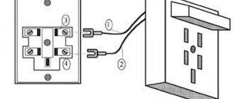
Since not all consumers can boast of having a third wire in their wiring, residents of such premises have to make do with what they have. The simplest circuit for connecting an RCD is to install a protective element after the input circuit breaker and the electric meter. After the RCD, it is important to connect circuit breakers for different loads with the corresponding shutdown current. Please note that the operating principle of RCDs does not provide for disconnecting current overloads and short circuits, so they must be installed together with circuit breakers.
Rice. 1: Connecting an RCD in a single-phase two-wire system
This option is relevant for apartments with a small number of connected devices. Since if there is a short circuit in any of them, shutting down will not bring any noticeable inconvenience, and finding the damage will not take much time.
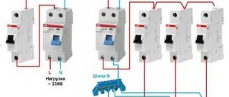
But, in cases where a sufficiently branched power supply circuit is used, several RCDs with different operating current values can be used.
Rice. 2: connecting an RCD in a branched single-phase two-wire system
In this connection option, several protective elements are installed, which are selected according to the rated current and operation current. As general protection, an incoming 300 mA fire protection RCD is connected here, followed by a neutral and phase cable to the next 30 mA device, one for sockets, and the second for lighting; a pair of 10 mA units are installed for the bathroom and nursery. The lower the response rating is used, the more sensitive the protection will be - such RCDs will operate at a significantly lower leakage current, which is especially important for two-wire circuits. However, it is also not worth installing sensitive automation on all elements, since it has a high percentage of false positives.
With grounding
If there is a grounding conductor in a single-phase system, the use of an RCD is more appropriate. In such a scheme, connecting the protective wire to the device body creates a path for current leakage if the insulation of the wires is broken. Therefore, the protection will operate immediately in the event of damage, and not in the event of electric shock to a person.
Rice. 3: Connecting an RCD in a single-phase three-wire system
Look at the figure; the connection in a three-wire system is made in the same way as a two-wire system, since only a neutral and phase conductor are required for the device to operate. The grounding device is connected only to the protected objects through a separate grounding bus. Zero can also be connected to a common zero bus; from the zero contacts it is routed by wires to the corresponding devices connected to the network.
As in a two-wire single-phase circuit, with a large number of consumers (air conditioner, washing machine, computer, refrigerator and other amenities of civilization), an extremely unpleasant option is the freezing of all of the above electronic circuits with loss of data or disruption of their functionality. Therefore, several RCDs can be installed for individual devices or entire groups. Of course, connecting them will result in additional costs, but will make finding damage a more convenient procedure.
What mistakes should you avoid?
Before connecting, be sure to double-check the technical specifications of the devices. The rated current must be equal to or higher than the same parameter for the input circuit breaker. The values can be easily determined by the markings.
Electricians recommend choosing a protective device one step higher, that is, for a 50A circuit breaker, a 63A RCD is suitable.
You can correctly calculate the parameters, choose a machine and an RCD with the correct rating, but make a small mistake during installation, as a result of which the system will be useless.
For example, beginners often confuse tires. It should be remembered that I use different buses for the neutral conductor and the ground wire. In addition, each device requires a separate bus: for 5 RCDs - 5 buses.
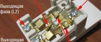
Whatever connection scheme you use, the grounding conductor will not participate in it. All terminals are designed either for the phase wire (load) or for the zero wire (neutral)
In no case should the poles N and L be confused . They have letter designations on the body, and the wires differ in color, so you need to be careful.
If a false alarm occurs or, on the contrary, the device does not respond, the reason may be the following:
- “phase” and “ground” are connected after the RCD;
- incomplete connection - conductor N is not inserted into the corresponding terminal;
- “zero” and “ground” are connected in the socket;
- confusion between connecting two or more RCDs to electrical installations.
In practice, there are many more errors, since different schemes are used. The more devices are involved in assembling the electrical panel, the more careful you need to be when connecting.
Connecting an RCD in a two-phase network
Two-phase power refers to non-standard connections, where a converted old-style 127 V transformer was reconnected into a triangle for modern 220 V consumers, which are powered by linear voltage from it.
Rice. 4: Connecting an RCD in a two-phase system
To connect a residual current device to a two-phase circuit, it is necessary to disconnect both wires at the input to the panel, since each of them is under potential. Then each of the phases is connected to the corresponding phase terminals and neutral terminals, further observing their polarity. Unlike a single-phase system, circuit breakers at the output of the RCD must be installed for each line, or they can be replaced with one two-pole one.
RCD installation instructions
First you need to choose a place to mount the device. There are 2 options: panel or cabinet. The first resembles a metal box without a lid, fixed at a height convenient for maintenance.
The cabinet is equipped with a door that can be locked. Some types of cabinets have openings so that you can take meter readings without specially opening the door and turn off the devices.
Protective devices are fixed on mounting DIN rails located horizontally. The modular design of automatic devices, difavtomats and RCDs allows you to place several pieces on one rail
The neutral wire is always connected to the left terminals at the input and output, and the phase wire to the right terminals. One of the options:
- input terminal N (upper left) – from the input circuit breaker;
- output N (lower left) – to a separate zero bus;
- input terminal L (upper right) – from the input circuit breaker;
- output L (lower right) – to group machines.
By the time the protective device is installed, circuit breakers may already be installed on the panel. To organize the arrangement of devices and wires, you may have to rearrange the devices in a certain order.
We present an example of installing an incoming RCD in an electrical cabinet that already has a meter, an incoming circuit breaker and several circuit breakers for individual circuits - lighting, socket, etc.
Image gallery
Photo from
IEK brand metal distribution board
A set of protective devices before installing an RCD
Choosing a location for installing an RCD
The procedure for connecting wires to the device
Never connect an RCD at the input - it always follows the general input circuit breaker. If a counter is used, the residual current device moves to the third position from the input.
Description of the connection process:
- We install the device on the DIN rail to the right of the machine - just touch it and press with a little force until it clicks;
- we stretch the cut and stripped wires from the machine and the zero bus, insert them into the upper terminals according to the diagram, tighten the fastening screws;
- In the same way, insert the wires into the lower terminals and tighten the screws;
- testing - first turn on the general circuit breaker, then the RCD, press the “Test” button; When pressed, the device should turn off.
To make sure the connection is correct, leakage current is sometimes simulated. Take two working wires - “phase” and “ground”, and simultaneously connect them to the base of the electric lamp. A leak appears and the device should work immediately.
Connecting an RCD in a three-phase network
Protection of devices powered by three phases at once is carried out according to a similar principle, with the difference that the RCD is selected for four outputs. An example of connection is shown in the figure below:
Rice. 5: Connecting an RCD in a three-phase system
As you can see, in this case, the protective device is also connected after the electric meter and the introductory packet. Individual circuit breakers that respond to phase short circuits are already connected behind it, and, if necessary, more sensitive RCDs are connected to create selective operation for certain groups of consumers.
Since installing a separate device for each phase is too expensive, group RCDs are used in three-phase circuits, which work with all elements of the line at once.
Video description
Incorrect connection diagrams for RCDs and automatic machines, as well as real examples when the RCD did not work correctly, are described in this video: The
second problem, after the correct selection of device parameters, is errors during installation, which leads to the uselessness of the protection system. An example is the banal mix-up of tires.
Attention! It is strictly forbidden to mix up the poles “N” and “L”. The device body usually has these designations, and the wiring should vary in color.
If after installation the device shows constant operation or, on the contrary, does not want to respond, then most likely:
- a phase connection to ground occurred after exiting the protection device;
- the installation was carried out poorly, for example, one of the wires is in poor contact with the terminal;
- there was a connection between the neutral wire and the ground in one of the sockets;
- When connecting a circuit of several RCDs, confusion occurred.
In practice, it is not realistic to foresee and describe all possible errors, because they depend largely on the switching scheme used. And the more complex it is (the more devices are included), the more important it is to be attentive.
Basic mistakes when connecting an RCD
When connecting an RCD, many people make common mistakes that can have very serious consequences for a person. To avoid them, follow these rules:
- the input terminals of the residual current device must be connected only after the corresponding circuit breaker; direct connection to the network is unacceptable;
- observe the correspondence of neutral and phase contacts, their designation is specifically indicated on the housing;
- when installing wiring, carefully follow the diagram, especially for objects with branching, a large number of connected objects and several RCDs for them;
- if there is no grounding conductor in an apartment or house, then it should never be replaced with a wire thrown over heating radiators or water pipes; grounding must be made in accordance with the rules;
- pay attention to the performance characteristics of the purchased devices (rated operating current and shutdown current) and their compliance with the network parameters, for example, if a current of 50A can flow in the line, then the device should be selected at least 63A.
To protect yourself during connection, follow basic electrical safety rules.
Device of differential automatic machine AD67-2 S25 100 mA
Now let's see what's inside the TEXENERGO AD67-2 automatic rifle. Let me remind you that functionally it differs from an RCD only in that, in addition to leakage current protection IΔn = 100 mA , it also has two overcurrent protections - thermal and electromagnetic. This is indicated by the inscription “C25”. This means that its time-current tripping characteristic “C” has a rated current In = 25 A.
I wrote about this in detail in an article about the characteristics of circuit breakers.
This machine occupies 4 modules on a DIN rail and actually consists of a two-pole circuit breaker with a rated current of 25 A and an RCD with a rated current of 100 mA:
AD67-2-difavtomat TEXENERGO
Unscrew the cover covering the lower terminals of the 2p machine:
AD-67 wires going from the machine to the RCD
The colors are slightly incorrect - phase is blue, zero is red. However, no one sees these wires.
Next, we drill out two long pins, and the device splits into two functional parts:
AD 67 decomposes into 2 parts - automatic and RCD
The connection between these devices is a lever protruding from the RCD, which operates the opening mechanism of the machine. By the way, this device is another argument in favor of the fact that when there is a machine and an RCD in the circuit, it is better to put the machine first.
That's it, now these are two independent devices, and they can be used separately. But it is not necessary, so as not to fool those who climb into the electrical panel later - the inscriptions on them do not reflect the essence. And most importantly, the resulting RCD does not have breaking contacts, and can only be used in conjunction with a circuit breaker.
AD-67 From one device - two, automatic and RCD
And if we have already opened a 2p circuit breaker earlier (there are 2 1p circuit breakers that have an on/off connection inside), then it’s worth looking at the electronic RCD device:
“Noname” electronic RCD, isolated from TEXENERGO AD-67
Drill out the stud rivets:
Internal structure of an electronic RCD
Here, in addition to the “Test” button, as in the VD-67 RCD discussed above, there is a “Return” button, which must be pressed after the AD-67 is triggered by the leakage current.
Electronic RCD AD-67-2, device from the inside
The electromagnet has an armature, which is pressed inward when cocked. When there is a leak, the armature is “squeezed out” from the electromagnet coil and “transmits information” through the lever of the opening mechanism to the circuit breaker.
That is, to turn on the blood pressure after activation, you need to perform two actions - press “Return” and raise the control knob of the machine. In RCD VD and difavtomat RCBOs, one action is enough - raise the control handle to position “1”.
Electrical circuit of the electronic automatic machine AD67-2
Once again: opening for both leakage and overcurrent occurs using the same power contacts. This can be seen from the diagram.
Scheme of an electronic RCD with an AD-67 assault rifle
The circuit differs from a mechanical RCD in the presence of overcurrent protection, and in the fact that the electromagnet “K” is powered from the differential transformer “D” not directly, but through an analog amplifier (key circuit) “A”. The amplifier is powered from output pins N and 2.
It gives some thought to the fact that the phase and zero on the device diagram and on the diagram in the passport are mixed up. This is probably not just a matter of carelessness on the part of the draftsmen. The point is that the RCD and Dif don’t care where the phase is and where the zero is - it only cares about the currents along the two wires (operating current and current difference).
The internal circuit of the electronic RCD, the photo of which is shown above, is assembled on a thyristor. I discuss it in detail in the article Internal circuit of an electronic RCD on a thyristor.
Safety regulations
If you decide to connect the RCD yourself, the success and safety of the work performed will depend on your compliance with the safety rules:
- Before starting installation operations, be sure to remove the voltage from the area (after disconnecting it would be a good idea to check the presence of potential with an indicator);
- Take care of the marking of the wires - this will make it much more convenient to connect the device so as not to confuse the leads;
- Be sure to use factory terminals and clamps, and never allow twisting, soldering or other connections with poor contact;
- After installation, check the reliability of the connections and the presence of sufficient insulation on all current-carrying elements;
- When commissioning, be sure to check the functionality by pressing the test button;
- When you first apply voltage to a newly installed device, it may fly apart due to manufacturing defects or installation defects, so it is better not to stand nearby or take measures to protect your eyes.
Before applying voltage after completing installation, be sure to ensure that no one in your household or colleagues touches live elements.
Main characteristics of RCD
Let us highlight the main technical characteristics that you need to pay attention to when choosing an RCD for a residential premises before starting repairs. These include:
- number of poles: two-pole and four-pole RCD;
- mains voltage: 220 or 380 V;
- rated load current of the network, it ranges from 16 to 100 Amperes;
- conditional short circuit current – can vary from 3 to 15 kA. This value shows the reliability of this RCD, and its ability to resist when a short circuit occurs;
- device design – electronic or electromechanical;
- the principle of its operation (Ac, A, B, S or G);
- its switching capacity.
Switching capacity - denoted by Im; represents the maximum value up to which this device will respond. This value must be at least 500 A.
Attention! When choosing an RCD, keep in mind that it is better to purchase electromechanical devices, as they are considered more reliable and cheaper.
For a regular voltage network of 220 Volts, conventional two-pole devices are optimal. But for a three-phase network with a voltage of about 380 V, you should choose the four-pole RCD devices we have already mentioned.
Basic elements and characteristics of RCD
Modern protective devices are not recommended for installation in houses with old wiring. In such premises, current leakage often occurs, which leads to instability of the entire network and significant voltage surges. As a result, the RCD may trip for no reason at all.
Typically, in residential premises, RCDs are installed to protect against current leakage in kitchens and bathrooms, since it is in these rooms that there is high humidity. These places are most saturated with electrical appliances, where current leakage can occur.
Purpose
Structurally, the RCD is made of a monolithic body with the possibility of manual and automatic control.
In manual mode you can:
- apply voltage to the controlled circuit;
- disconnect power from connected consumers;
- check the device’s serviceability using the “Test” button.
The automatic mode begins to work immediately after manual power supply and is only capable of shutting down the circuit when leakage currents occur in it. The function of re-switching on the RCD in the event of a power failure is used in some of the most complex designs.
The operational tasks of the RCD are:
- supplying voltage to consumers;
- elimination of false alarms during the passage of load currents;
- manual shutdown in normal mode and protective shutdown in case of insulation breakdown in a controlled circuit.
The operation of the RCD automation prevents:
- electrical injury to a person caught under voltage from an electrical installation;
- fires in the building due to faulty wiring.
Number of poles per RCD
The operating principle of the RCD is associated with the summation of currents in the comparison organ. All of them must pass inside a common magnetic circuit to create an overall balance. For example, a four-pole RCD can operate normally in a three-wire or two-wire circuit, but without the use of additional poles.
In this case, nothing will interfere with the work of the comparison organ, although this method is most often not economically feasible.
However, it is resorted to during construction with a single-phase network, which will be converted into a four-wire network or to ensure emergency replacement of a faulty device.