The only point that you should pay attention to is that to increase the load capacity of the clamps and the reliability of contact, you should choose double punctures.
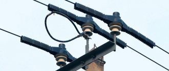
SIP-3 connection in loops
The choice of such piercing clamps is very wide and is presented on the market by different manufacturers.
NiledSicamEnsto
Niled RP150, 240
Sicam TTDC
Ensto Sliw17.2
On top they are equipped with two tightening bolts with a shear head. The most reliable way to remove the head is to use a spanner.
To connect protected SIP-3 wires with bare wires of AC grades, connecting branch clamps of a different design should be used. They have piercing teeth located on one side only. On the other hand, there is a smooth surface like an ordinary die.
NiledSicamEnsto
Niled RPN150
Sicam NTDC
Ensto Slip 32.2
Be sure to brush the bare, bare wire before installing the clamp.
If you do not have sealed punctures available, you can use other die clamps. For example SLW25 from Ensto.
The clamp itself is filled with a conductive anti-oxide lubricant, which improves contact and prevents moisture from getting into the connection.
To protect from moisture from the outside, the die is covered with a special casing, which is made of plastic resistant to ultraviolet radiation.
Connecting two wires on one puncture
Another important point when using piercings is that it is prohibited to connect more than one branch on one sealed piercing clamp, unless this is provided for by its design.
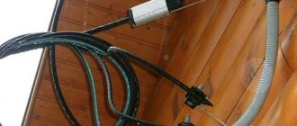
It would seem that you have two outgoing cables with a cross-section of 6mm2. If you twist them together or even insert them inside the clamp without twisting, then nothing prevents you from tightening the contact in this way. This technique is often used when connecting several lamps through one piercing clamp.
However, just the same contact over the entire area of the outgoing core will no longer be sufficient. Moreover, in this case the insulating rubber gasket will not be able to compress the wire from all sides. And accordingly, we are no longer talking about any tightness. Moisture will easily penetrate inside the puncture, flowing down the surface of the insulation of the two wires.
SIP-3 connection in span
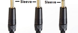
To connect SIP-3 wires in a span, several types of sleeves can be used. For example, crimp connectors from Niled - MJRP.
On isolated low voltage lines VLI-0.4 kV, similar connecting sleeves MJPT or GSI-N are used.
However, it is prohibited to use the same sleeves on a high-voltage SIP-3 wire!
To install the crimp connector, you will definitely need a mechanical or hydraulic press with special dies E173 and E215.
To ensure reliable sealing of the connection, it is necessary to compress the outer edges of the sleeve, which have metal rings.
Characteristics of connecting sleeves:
NiledSicam
Niled MJRP
Sicam MJPT G28
If you do not have a press, insulated wires in the span can be connected in another way. It is especially common during prompt emergency repairs in the event of a SIP-3 break.
For this purpose, collet-type connecting clamps are used - MHV. They don't require a press.
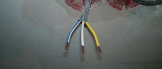
The connected ends of the wire are stripped in turn of insulation to a length of slightly less than half the length of the clamp.
After this, insert it all the way into the collet clamp and, using two standard open-end wrenches, tighten the corresponding cap nut. Tightening occurs until the collets inside the clamp come off.
This moment should be accompanied by a characteristic click.
Characteristics of collet clamps for VLZ:
When installed on a VLZ-6-10 kV protected wire, collet clamps must be installed complete with slide-on or heat-shrinkable covers. Moreover, here you need to use high-voltage thick-walled thermotubes.
Before connecting the wires, do not forget to first put heat shrink on the SIP-3 itself. And only then carry out their sleeving.
After tearing, the heat-shrinkable cover is pushed onto the tightened clamp and the tube is heated using a gas burner, gradually shifting the heating zone from the middle to the edges.
Wire rolling
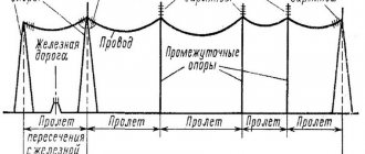
The installation of SIP begins after installing the VLI supports with clamps attached to them.
Anchor clamps are installed on the anchor supports that carry the tension force of the conductors, and supporting clamps are installed on the intermediate supports located between them.
Installation of SIP cable begins with its unrolling. To do this, perform the following steps sequentially:
- Special unrolling rollers are installed on all supports of the anchor span on which the wire is mounted. On the extreme, anchor supports, the rollers are fastened with a belt; on the intermediate supports, the rollers are suspended on a hook in the eyes for supporting clamps;
- A drum with wire is installed behind one of the outer supports of the span. It is located in a vertical position on special stands that allow it to rotate during the rolling process. In order for the wire to enter the roller at a flatter angle, it is recommended to install the drum from the support at a distance not less than its length;
- On the other side of the mounted span there is a drum on which a leader cable is wound, usually a synthetic rope with a diameter of 10–12 mm, depending on the rolling method (manual, mechanized);
- Next, the leader cable is rolled out manually. This operation is performed by sequentially lifting onto each support, threading the cable into the roller and further pulling it;
- After lifting to the last support, the leader cable is connected to the SIP using a special stocking and swivel that prevents the wire from twisting during the rolling process.
This is where the preparatory procedures end, and the actual rolling out of the wire begins. The leader cable slowly, without jerking, is pulled in the opposite direction. During mechanized rolling, the drum winding device is driven by an internal combustion engine with a gearbox; the leader cable can also be pulled out manually.
During the rolling process, the wire, following the leader cable, rises to the support and takes its place on the rollers. Rollers and drums must be located so that when rolling there is no friction of the wire on the ground, support and other structures. It is unacceptable to use a technology in which the wire is rolled out on the ground and then lifted onto a support.
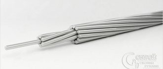
Cable structure
The structure of the speaker wire resembles an ordinary rag rope, but curled from two materials. There is a steel cable in the middle. It is made of one or more thin wires. The purpose of a steel cable is to give the conductor strength, flexibility and resistance to stretching. It performs a mechanical, load-bearing function.
From the outside, many aluminum wires are wound around the steel cable. The majority of the load current flows through them. If the AC cable is designed for a large cross-section, then the winding is done layer by layer, alternating directions. This avoids spontaneous unwinding of the structure.
Structure of a non-insulated AC cable.
The resulting conductor combines the advantages of the materials used:
- steel strength;
- good electrical conductivity of aluminum;
- light weight of the resulting product.
The final mass of the cable is also affected by the absence of an outer insulation layer.
Operating conditions and characteristics of the speakers
The characteristics of speaker conductors vary greatly depending on their cross-section. But there are also common properties that are inherent in all products in this category:
- operating temperature from –60 to +40°C (ideal for the CIS);
- solid service life of 45 years;
- maximum permissible temperature +90°C;
- temporary tensile strength - from 160 MPa;
- guaranteed period of work 4 years;
Characteristics of steel-aluminum wires of the AC grade.
Other properties are determined based on the cross-section and length of the wire. The electrical parameters of some AC cables are shown in the table.
| Wire type | Continuous permissible current, A | Maximum resistance of 1 km of wire, Ohm |
| AS-16/2.7 | 111 | 1,78 |
| AS-50/8.0 | 210 | 0,59 |
| AS-70/11.0 | 265 | 0,42 |
| AS-120/19.0 | 390 | 0,24 |
| AS-150/19.0 | 450 | 0,20 |
And below are the mechanical properties of wires of the same brands.
| Wire type | Diameter of aluminum/steel wire, mm | Weight of 1 km cable, kg |
| AS-16/2.7 | 1,85/1,85 | 64,9 |
| AS-50/8.0 | 3,20/3,20 | 195 |
| AS-70/11.0 | 3,80/3,80 | 276 |
| AS-120/19.0 | 2,40/1,85 | 471 |
| AS-150/19.0 | 2,80/1,85 | 554 |
What do the letters AC mean?
The abbreviation AC refers to a bare aluminum wire with reinforcement in the form of a steel cable. The letters in the markings have the following meaning:
- A - the current-carrying core is made of aluminum;
- C - the wire is reinforced with a steel core.
The numbers following the letters in the marking indicate the cross-sections of the cores used. For example, in the AC-16/2.7 conductor, for the aluminum part it is 16 mm2, and for the steel part it is 2.7 mm2.