Repair instructions for SF6 circuit breaker VGT-110 - Documentation
Contents of the material
DOCUMENTATION.
6.1. List of reporting documents.
6.1.1.
Based on the results of the work performed, the following types of reporting documents are drawn up: - act of completion of equipment repair work;
— list of equipment (appendix to the act);
— typical scope of repair;
— statement of completed work;
— a list of replaced units and parts during the repair of electrical equipment.
6.1.2. Repair documentation (statement of completed work, test report) for each piece of equipment is stored in the masters’ room at the outdoor switchgear.
6.1.3. The storage period for repair documentation is until the next major overhaul.
6.1.4. The person responsible for the safety of repair documentation is the foreman of the team for repairing outdoor switchgear and 6 kV switchgear equipment.
6.2. Forms of reporting documents.
— the act of completed equipment repair work is drawn up in the form of Appendix 1;
— typical scope of current repairs of the VGT-110 circuit breaker according to the form of Appendix 2;
— typical volume of average repair of the VGT-110 circuit breaker according to the form of Appendix 3;
— typical scope of overhaul of the VGT-110 circuit breaker according to the form of Appendix 4;
— statement of completed work TR of the VGT-110 circuit breaker in the form of Appendix 5;
— statement of work performed on the CP circuit breaker VGT-110 in the form of Appendix 6;
— statement of work performed on the CP circuit breaker VGT-110 in the form of Appendix 7;
— a list of replaced units and parts during the repair of electrical equipment is drawn up in the form of Appendix 10.
6.3. Drawing (sketch) of a general view.
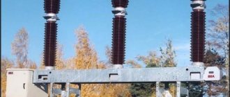
Figure 1. General view of the VGT-110 circuit breaker
6.4. Repair checklist.
6.4.1. In accordance with clause 2 of Appendix 7 POKAS(rem) Book No. 1 No. 00-18-01POKAS(rem) the development of control charts is not required if there are approved standard statements of scope of work, which are annex to the technical specifications.
Chief Engineer
ACT OF EXECUTED WORKS
The commission appointed by order No. _______ dated _______________, consisting of:
Commission members: _____________________________________________________
Based on the submitted documents (reporting repair and technological documentation) and the results of acceptance tests, it accepted the equipment from repair and established an assessment of the quality of the repaired equipment (the list of equipment is in the appendix to the report).
The warranty period for repaired equipment is ______month.
Equipment with other warranty periods: _______________________________________________________________________
The quality of repair work performed is assessed by ________
Application:
List of equipment accepted for repair on ____ sheets.
Note
: The report is drawn up for a group of equipment that is part of one installation (system)
Chairman ________________________________________________________________
Commission members
:_______________________________________________
SF6 gas core switch VGT-110 (U1, UHL1*)
- Highest operating voltage, kV 126
- Rated current, A 2000, 3150
- Rated shutdown current, kA 40
- Switching temperature of heating devices, ºС 1±1
- Weight, kg 1570
- Description
- Characteristics
- Photo
- Files
Purpose of the SF6 core switch VGT-110
VGT-110 circuit breakers are designed for switching electrical circuits in normal and emergency modes, as well as operating in automatic reclosure cycles in three-phase alternating current networks with a frequency of 50 Hz and a rated voltage of 110 kV.
Column switch design
The switches consist of three poles (columns) mounted on a common frame and controlled by one spring drive PPrM. Explosion-proof design.
Reduced effort to operate the switch. The energy required to extinguish short-circuit currents is partially used from the arc itself due to the special design of gas flow control units, which significantly reduces the drive load and increases reliability. The use of four stages of seals in conjunction with a hydraulic seal in the rotary mechanism shaft seal assembly ensures a consistently low level of leakage: no more than 0.5% per year.
Modern technological and design solutions in the field of application and processing of materials, the use of reliable components, including high-quality tires from leading foreign companies.
The steel parts of the switch and supporting metal structures have corrosion-resistant coatings.
SF6 circuit breakers VGT-110 can be supplied upon request with shortened factory support posts, as well as with or without high support posts.
Advantages of the SF6 circuit breaker VGT-110
- Maintaining the electrical strength of the column switch insulation at a voltage of 84 kV in the event of loss of excess gas pressure in the switch;
- Switching off capacitive currents without repeated breakdowns, low overvoltages;
- Low level of audible noise when triggered (meets environmental requirements);
- Low dynamic loads on foundation supports;
- The reliability and safety of the PPrM spring drive is confirmed by many years of experience in controlling column switches;
- The presence in the automatic control drive of two heating stages (anti-condensation and main) of the drive cabinet and monitoring of their serviceability;
- Components are purchased from leading, reputable domestic and foreign manufacturers;
- The block-modular design of the SF6 gas circuit breaker VGT-110 makes it possible to supply the customer with products in a convenient container with a minimum volume at minimal transportation costs, as well as to ensure convenient and prompt installation and commissioning, which are carried out under the guidance of a chief engineer.
Technical characteristics of the SF6 gas column circuit breaker VGT-110
Normalized switching current parameters, kA
— initial effective value of the periodic component
Normalized parameters of through short circuit current, kA:
— highest peak (electrodynamic withstand current), kA
— root mean square value of the current during its flow, kA
— short circuit current flow time, s
Timing of closing and opening contacts of poles s, no more
Gas pressure (SF 6), reduced to plus 20ºС, MPa, excess:
— warning alarm activation
— control blocking (or automatic shutdown with power-on blocking)
Rated supply voltage of the drive electric motor, V, alternating
Number of pairs of switching contacts for external circuits:
Switches of the VGT-110, VEB-110 series produced by OJSC "Uralelektrotyazhmash"
Among the wide range of electrical equipment produced by OJSC UETM, which includes hydrogen generators, large electric motors, transformers, thyristor excitation systems, converters for electric drive systems, a significant part in terms of production volume (up to 30%) belongs to high-voltage equipment.
The reliability of the devices is ensured by a high level of development and testing, careful selection of high-quality materials and components, high production standards, a quality system certified for compliance with ISO 9001-2000 standards, a high degree of factory readiness, and installation of switches by the manufacturer’s specialists.
All high-voltage devices mass-produced by the plant are certified. In recent years, old oil-based high-voltage circuit breakers have been replaced by new generations of SF6 devices.
A distinctive feature of the new switches is a new arc extinguishing device based on the principle of self-generation. The principle of self-generation is that during the combustion of an arc, part of the SF6 gas located in its zone expands as a result of heating. In a limited volume, this creates additional pressure, which provides a blast that helps extinguish the arc.
Thus, the energy released in the arc is used to extinguish it. This makes it possible to reduce the work of the circuit breaker drive compared to the compression extinguishing principle, when all the energy required to extinguish the arc is generated by the circuit breaker drive. This principle is used in the new generation SF6 column switches of the VGT series produced by the Uralelectrotyazhmash enterprise for voltages of 110 and 220 kV and a rated current of 2500 A, with a shutdown current of 40 kA (Fig. 1).
The production of VGT series switches began at the plant in 1998.
To date, more than 1,300 switches of this series have been shipped to customers. The VGT-110 switch is controlled by a three-pole spring drive PPrK. Switches VGT-220 are maximally unified with VGT-110. On the same frame there are two half-poles with a unified arc extinguishing device installed on the 220 kV support insulation.
The switch is controlled pole-by-pole by the same PPrK drive. In addition to the basic model, switches of this series are also available in the following versions:
- with a reduced length along the frame (VGTZ);
- in earthquake-resistant design;
- in a cold-resistant version (with a mixture of SF 6 and CF 4 gases) for operation at temperatures down to minus 55 o C.
Rice.
1. SF6 gas column switch VGT-110 The main advantages of this device include the following.
- High reliability provided by:
- reduced, as already noted, efforts to operate the switch;
- the use of double seals and a liquid seal in the movable seal, which ensures that leaks remain at the level of 0.5% of the mass of SF6 gas per year;
- careful selection of components and materials, the use of components from foreign companies: European seals, German density meters, etc.;
- reliable corrosion protection, which is ensured by the use of hot-dip galvanizing of steel parts.
- High factory readiness, simple and quick installation, which must be carried out under the guidance of representatives of the manufacturer. During installation, the necessary control checks and pumping of SF6 gas from a transport pressure of 0.05 MPa to a working pressure of 0.4 MPa are carried out. Everything necessary for the initial filling of the switch with SF6 gas: a cylinder with SF6 gas, hoses with connecting tips, etc. are included in the delivery set.
- The overhaul interval, during which practically no maintenance of the switch is required, except for periodic pressure monitoring, is at least 20 years. The average service life of a circuit breaker is 40 years.
The mechanical life of the switch is 10,000 V-O operations.
- Even if the excess gas pressure drops to zero, the switch can turn off the load current and maintain the highest operating voltage for at least 3 hours.
- The switches disconnect capacitive currents of unloaded lines without repeated breakdowns and practically without overvoltages.
- Full interchangeability in terms of installation dimensions and control circuits with previously produced low-oil switches of the VMT series.
- Switching life of the circuit breaker, which is 20 operations of switching off the full current of 40 kA for each pole. At the same time, foreign companies guarantee 20 operations in total per switch, which, when calculated using the methods of companies, for example ABB, gives 10-12 operations per pole.
Rice.
2. SF6 tank circuit breaker VEB-110 Since 2001, expanding the range of new generation switches, the plant began production of SF6 tank circuit breakers of the VEB-110 series for rated currents of 2000 and 2500 A, breaking current 40 kA , controlled by the same spring drive type PPrK (Fig. 2). The arc extinguishing device of this device is unified with the corresponding components of the VGT-110 circuit breaker.
The main difference between VEB-110 and VGT is the presence of built-in current transformers: 4 or 5 transformers per phase.
One of these transformers is a measuring transformer with an accuracy class of 0.2 (0.2S), the rest are protective with an accuracy class of 5P or 10P. It should be especially noted that the calibration interval of these current transformers is 20 years. In addition, a number of other advantages of the VEB-110 switch should be noted.
- The switch is equipped with an automatic heating system, due to which it is produced in the UHL1 climatic version and can operate in cold climates at temperatures down to minus 55 o C on pure SF6 gas. The heating system automatically turns on and off at a temperature of minus (25±5) o C.
- The switches have an even higher degree of factory readiness, since they are supplied fully assembled and adjusted and during installation only require checking some adjustments after transportation and pumping of SF6 gas from transport pressure to operating pressure (0.4 MPa). Everything necessary for the first injection of SF6 gas is included in the delivery set. Installation and commissioning at the consumer must be carried out by representatives of the plant.
- The switches are equipped with an emergency pressure relief valve.
- The VEB-110 switch has the same service life indicators as the VGT-110, the same overhaul interval of 20 years, service life of 40 years and warranty period of 5 years. In July 2004, the 300th switch of this series was manufactured. The series of SF6 column switches for voltage 220-500 kV, rated current 3150 A, shutdown current up to 50 kA is being updated.
These switches use a compression arc extinguishing method.
After the modernization, the switches of this series, which received the name VGUG, began to be equipped with autonomous hydraulic drives PGV-12 instead of pneumatic drives. Recently, a new circuit breaker for the 750 kV voltage class appeared in the company's product range. The SF6 circuit breaker VGG-750 with a rated current of 3150 A and a breaking current of 40 kA has passed all the necessary tests, been accepted by the interdepartmental commission with the participation of the Federal Grid Company and put into production. The production of SF6 gas switches VGK has begun for a voltage of 220 kV in one break, a breaking current of 31.5 kA, a rated current of 3150 A (Fig. 3).
It should be noted that the device has a high switching life: 25 switching operations and 15 switching operations of full current per pole.
Rice.
3. SF6 gas circuit breaker VGK Between repairs is at least 15 years, average service life is 30 years. The switch has a pole-pole control of a double-acting PGV-4 spring-hydraulic drive. Along with the continuation of development and improvement of switches, in order to ensure comprehensive supplies of remote power equipment, the plant carried out developments and in 2003 began serial production of SF6 measuring current transformers and disconnectors for a voltage of 110 kV. The RPD-110 type disconnector (Fig. 4) consists of three-pole groups of disconnectors and grounding switches. The disconnector pole consists of two rotating insulator columns. Insulating columns on rotary bases rotate on rolling bearings. Insulators can be porcelain, obtained exclusively from imports, or polymer.
The current-carrying disconnector system contains one feed-through contact located at the top of the column, provided by lamellas surrounding two coaxial copper rods.
The reliability of this contact is increased by a parallel circuit of flexible connections. The main open contacts are made in the form of a cam at the end of one conductor and contact fingers at the end of the other. All contact surfaces are silver plated. The disconnector is equipped with one or two grounding switches and corresponding mechanical interlocks. The disconnector and grounding switches are controlled by motor or manual drives. Motor drives have the ability to be operated manually. Both drives are equipped with electromagnetic interlocking to prevent incorrect operations and have permanently switched on anti-condensation heating.
The motor drive is also equipped with additional heating, which is switched on and off automatically depending on the temperature.
All disconnector control rods are equipped with self-lubricating proprietary spherical joints that require no maintenance during their entire service life. Disconnectors are supplied from the factory fully adjusted and are equipped with supporting metal structures (racks). For the reconstruction of switchgears, there is a version of disconnectors without support posts, intended for installation on existing supports.
RPD-110 is produced for currents of 1600 and 2500 A, the thermal resistance current of the disconnector is 40 kA for 3 s, the grounding switch is 40 kA for 1 s.
Switching capacity - 1 A at an interpolar distance of 1800 mm and 2 A at 2000 mm. The mechanical resource for the main circuits and grounding circuits is 10,000 V-O cycles. The main advantages and benefits of the disconnector include:
- the use of high-strength rod porcelain or polymer insulators;
- welded aluminum current conductors with a minimum number of contact connections provide stable electrical resistance for many years;
- absence of additional springs in the main contacts;
- application of rolling bearings in
- rotating bases. This ensures stability of mechanical characteristics under high bending loads;
- self-lubricating spherical joints provide ease of adjustment and reduce effort during operation;
- disconnectors are supplied by the factory fully adjusted; the factory package includes installation metal structures (racks);
- the fixed position of the driving levers of the drive with the transition beyond the “dead center” eliminates the possibility of involuntary switching under the influence of external factors; additional safety provided by the location of the drive outside the movement zone of the disconnector blades;
- reliable anti-corrosion coating of all metal structures with hot zinc;
- warranty period is 5 years, average service life is 40 years.
Rice.
4. Disconnector RPD-110 Another non-switching device mastered in production - the gas-insulated current transformer TRG-110 (Fig. 5) is designed to operate at ambient temperatures down to minus 55 o C. The primary winding consists of four rods that can be switched in series or parallel. The secondary windings in the screen are mounted on a supporting support, inside which there are leads that exit through a sealed terminal block at the bottom of the device.
There is a valve at the top that protects against excessive pressure. Transformers have primary currents from 300 to 2000 A. Secondary current 5 A.
Rice.
5. SF6 current transformer TRG-110 The transformer is equipped with four secondary windings, one measuring accuracy class 0.2 or 0.2S and three protective accuracy classes 5P or 10P. thermal resistance current up to 40 kA. SF6 gas leakage is no more than 0.5% per year. Switching the transformation ratio is carried out by rearranging the jumpers connecting the rods of the primary winding. Since there is no solid insulation in the transformer, there are no partial discharges.
Interverification interval is 10 years. Average service life 40 years , warranty period 5 years . For a voltage of 35 kV, SF6 tank three-pole switches VGB-35 are produced.
This switch, all three poles of which are located in one tank, when filled with pure SF6 gas, can operate in any climate zone - from tropical to cold. The simple and reliable arc extinguishing device of this switch, containing the minimum possible number of elements and using the principle of rotation of the electric arc in the magnetic field created by the current itself, ensures the absence of overvoltages when disconnecting small inductive currents and disconnecting capacitive currents up to 630 A without repeated breakdowns.
The presence of the only dynamic seal with a liquid seal for a three-pole switch and a high-tech aluminum welded tank guarantees a very low level of natural SF6 gas leaks - no more than 0.5% per year. The switches are produced for a current of 630 A, the shutdown current is 12.5 kA.
The switch is equipped with built-in current transformers, two measuring and two protective ones per pole. The switch is controlled by an electromagnetic drive of direct or alternating current. The circuit breaker is supplied filled with SF6 gas to operating pressure and is fully factory ready. The testing center for high-voltage electrical equipment, accredited in two certification systems - GOST R and ENERGOSERT, allows us to carry out almost all types of tests on a wide range of high-voltage devices, transformers and converter equipment.
Authors: Rotblut A.R., Chief designer of high-voltage equipment of Uralelectrotyazhmash OJSC
Kibel V.M., Head of the testing center for high-voltage electrical equipment of Uralelectrotyazhmash OJSC
SF6 circuit breakers 110 kW, 220 kW
Various gas mixtures are often used to extinguish an electric arc. 110 kV and 220 kV SF6 circuit breakers operate precisely on this principle and can be used for operation in emergency situations.
Design and types
Gas-insulated high-voltage circuit breakers are operational control devices for monitoring high-voltage power supply lines. These devices have a very similar design to oil ones, but at the same time, they use not an oil mixture, but a gas compound to extinguish the arc. Often this is sulfur. Oil switches require special care: according to regulations, periodic oil changes and cleaning of working contacts are required. SF6 ones do not need this. The main advantage of SF6 gas is its durability: it does not age and minimally pollutes the mechanical parts of the device.
Photo - high voltage equipment
- Core (HPL 245B1, MF 24 Schneider Electric);
- Tank (242PMR, DT2-550 F3 - Areva manufacturer).
The SF6 column circuit breaker is a standard disconnecting device that operates on one phase only (for example, LF 10 from Schneider Electric). It is used for 220 kV network. Structurally they consist of two systems: contact and arc extinguishing. Both of them are located in a container filled with SF6 gas. They can be either manual (control is performed exclusively mechanically) or remote. Due to this separation, they have quite large overall dimensions.
Column switch block
It is a prefabricated free-standing block of a supporting metal structure, intended for outdoor installation in electrical installations of three-phase alternating current of industrial frequency 50 Hz, as part of open switchgears (OSD) of voltage class 110 kV, in areas with temperate and cold climates, in normal and polluted atmosphere conditions . Assembly and installation of the block is carried out directly at the construction site.
- 1. Column switches voltage class 110 kV
The unit is equipped with high-voltage circuit breakers of 110 kV voltage class. Products from different manufacturers present in both the Russian and foreign markets can be used as optional equipment. The developed blocks can be used both in the new construction of substations and in the reconstruction of facilities.
At the customer’s request, the support block can be manufactured in accordance with the manufacturer’s own choice of high-voltage circuit breakers for the voltage class 110 kV with a short period of adjustment of the design parameters, while maintaining the connecting dimensions to the construction part (foundations) of the substation (PS).
- 110, 220 kV blocks are structurally made up of support posts fastened together by crosspieces or jibs and beams installed on them for equipment, usually of the same type.
- Metal structures are made from steels St3 and 09G2S, depending on climatic conditions, as well as seismic activity of the outdoor switchgear construction site.
- All blocks are designed with bolted connections, and are also supplied in the form of enlarged assembly units, which eliminates on-site welding when installing blocks, and also speeds up assembly.
- The presence of markings on each product in the form of a glued aluminum marking plate with the product drawing number in a visible place makes assembly convenient and eliminates the depersonalization of elements.
- The ability to install secondary switching cabinets, hanging cable trays, which reduces the cost of manufacturing separate support frames and additional racks, as well as additional foundations for them.
- After manufacturing in production, the unit undergoes control assembly in the workshop with the preparation of an acceptance test report. This eliminates the risk of the block not being assembled at the construction site.
Rated voltage, kV: 110 Highest operating voltage, kV: 126 Rated current, A: 3150 Rated shutdown current, kA: 50 Thermal resistance current, kA (s): 50 (3) Own shutdown time, ms: 35 Total shutdown time, ms: 55 Internal turn-on time, ms: 62 Switches of the VGT series belong to high-voltage electrical switching devices in which the quenching and insulating medium is: for version U1 - SF6 gas, and for version HL1* - a mixture of gases (SF6 gas + tetrafluoromethane CF4). SF6 gas circuit breaker VGT-110 column type. It consists of three poles (columns) mounted on a common frame and mechanically connected to each other. All three poles of the switch are controlled by one spring drive type PPrK. The drive has automatic control of 2 stages of cabinet heating and monitoring of their serviceability. Switches are manufactured in climatic versions U1* and HL1*. The natural level of SF6 gas leaks is no more than 0.5% per year. VGT-110 switches of the basic version with shortened factory supporting metal structures are completely interchangeable (in terms of connecting and installation dimensions) with low-oil switches of the VMT series.
| Parameter name | VGT-110II* -40/3150U1 | VGT-110II* -40/3150ХЛ1* | VGTZ-110II* -40/3150U1 | VGTZ-110II*- 40/3150ХЛ1* | ||||
| Rated voltage, kV | 110 | |||||||
| Highest operating voltage, kV | 126 | |||||||
| Rated current, A | 3150 | |||||||
| Rated breaking current, kA | 40 | |||||||
| Nominal relative content of the aperiodic component, %, no more | 40 | |||||||
| Parameters of through short circuit current, kA | ||||||||
| Highest Peak | 102 | |||||||
| Initial effective value of the periodic component | 40 | |||||||
| Thermal current | 40 | |||||||
| Thermal resistance current flow time, s | 3 | |||||||
| Switching current parameters, kA | ||||||||
| Highest Peak | 102 | |||||||
| Initial effective value of the periodic component | 40 | |||||||
| Current of unloaded lines, disconnected without repeated breakdowns, A, no more | 125 | |||||||
| Current of a single capacitor bank, disconnected without repeated breakdowns, A: | ||||||||
| With solidly grounded or insulated neutral | ||||||||
| With solidly grounded neutral | 0-300 | |||||||
| Inductive current of the shunt reactor, A | 500 | |||||||
| Own shutdown time, s | 0.035-0.005 | |||||||
| Total shutdown time, s | 0.055-0.005 | |||||||
| Minimum dead time during automatic reclosure, s | 0.3 | |||||||
| Own switching time, s | 0.062-0.018 | |||||||
| Diversity of operation of poles, s, no more | ||||||||
| When turned on | 0.002 | |||||||
| When disconnected | 0.002 | |||||||
| Gas consumption for leaks per year, % of gas mass, no more | 0.5 | |||||||
| Absolute gas pressure, normalized to plus 20°C, MPa (kgf/cm2): | ||||||||
| Filling pressure (nominal) | SF6 gas | 0,5 (5 | 0,5 (5 | |||||
| Gas mixture | 0,7 (7) | 0,7 (7) | ||||||
| Alarm pressure when full | SF6 gas | 0,44 (4,4) | 0,44 (4,4) | |||||
| Gas mixture | 0,62 (6,2) | 0,62 (6,2) | ||||||
| Blocking pressure (operation prohibition or forced shutdown with activation prohibition) when filling | SF6 gas | 0,42 (4,2) | 0,42 (4,2) | |||||
| Gas mixture | 0,6 (6) | 0,6 (6) | ||||||
| Gas mass, kg | ||||||||
| SF6 gas | 6,3 | 6,3 | ||||||
| Gas mixture: SF6 tetrafluoromethane | 4,2 3,5 | 4,2 3,5 | ||||||
| Test one-minute voltage frequency 50 Hz, kV | 230 | |||||||
| Lightning impulse test voltage (1.2/50 µs) | ||||||||
| Relative to earth | 450 | |||||||
| Between open contacts | 550 | |||||||
| Leakage distance of external insulation, cm, not less | 280 | |||||||
| type of drive | spring | |||||||
| Number of drives | 1 | |||||||
| Rated DC voltage of the drive control electromagnets, V (Power supply of the control electromagnets with rectified current is allowed, for example, from BPT-1002, BPNS-2 units, etc.) | 110 or 220 | |||||||
| Number of control electromagnets in the drive | ||||||||
| including | 1 | |||||||
| disconnecting | 2 | |||||||
| Operating voltage range of control electromagnets, % of nominal value | ||||||||
| Closing electromagnet | 80-110 | |||||||
| Trip solenoid | 65-120 | |||||||
| Nominal value of the steady-state value of direct current consumed by the control electromagnets, A, no more | ||||||||
| At 110 V | 5 | |||||||
| At voltage 220 V | 2.5 | |||||||
| Number of contacts switching for external auxiliary circuits (per drive) | 11 NO.+12 N.C.+2 slipping | |||||||
| Tripping current of switching contacts for external auxiliary circuits at voltage 110/220 V, A | ||||||||
| Alternating current | 10/10 | |||||||
| Direct current | 2/1 | |||||||
| Power of the electric motor of the closing spring plant, kW (one drive) | ||||||||
| 3-phase | 1.1 | |||||||
| universal | 0.75 | |||||||
| Rated voltage of the electric motor of the closing spring plant, V | ||||||||
| Three-phase AC | 230 or 400 | |||||||
| Universal single phase AC or DC | ~230 or =200 | |||||||
| Direct current | 110 | |||||||
| Winding time of closing springs, s, no more | 15 | |||||||
| Rated power of heating devices of one drive, W | ||||||||
| Constantly operating anti-condenser heating | 50 | |||||||
| Heating that automatically turns on at low temperatures 1st stage (turns on at 0°C) 2nd stage (turns on at -20°C) | 800 800 | |||||||
| AC power supply voltage for heating devices, V | 230 | |||||||
| Maximum vertical force on one foundation support (front and rear) that occurs when the switch is triggered (pulse, pulse duration 0.02 s), excluding the mass of the switch, N | ||||||||
| up | 17300 | |||||||
| down | 18400 | |||||||
| Static load on one foundation support, N | 9500 | |||||||
Switch operating conditions.
Designed for operation in open and closed (VGTZ series) switchgears in alternating current networks with a frequency of 50 Hz and a rated voltage of 110 kV in areas with moderate and cold climates (up to minus 55°C) under the following conditions:
- the environment is non-explosive, not containing aggressive gases and vapors in concentrations that destroy metals and insulation. Content of corrosive agents according to GOST 15150 (for type II atmosphere);
- the upper operating temperature of the air surrounding the switch is 40°C;
- the lower operating value of the air temperature surrounding the switch is: for climatic version U1* - minus 40°C, for version HL1* - minus 55°C;
- Ice with an ice crust thickness of up to 20 mm and wind speeds of up to 15 m/s, and in the absence of ice - with wind speeds of up to 40 m/s.
- Installation height above sea level is not more than 1000 m;
- The tension of the wires in the horizontal direction is no more than 1000 N.
When ordering, it is possible to supply switches in climatic version T1 (upper operating value of ambient air temperature plus 55°C).
SF6 gas switches VGT series
General information
SF6 gas circuit breakers of the VGT series are designed for switching electrical circuits in normal and emergency modes, as well as operation in automatic reclosure cycles in three-phase alternating current networks with a frequency of 50 Hz and a rated voltage of 110 and 220 kV.
Symbol structure
switch VGT-XII * -40/2500U1: VG - SF6 switch; T - symbol of the design; X - rated voltage, kV (110 or 220); II * - category according to the length of the leakage path along the external insulation in accordance with GOST 9920-89; 40 — rated shutdown current, kA; 2500 — rated current, A; U1 - climatic version and placement category according to GOST 15150-69 and GOST 15543.1-89. PPrK-1800S drive: P – drive; Pr - spring; K - cam; 1800 - static switching work, J; S - special.
terms of Use
The installation altitude above sea level is no more than 1000 m. The ambient temperature is from minus 45 to 40°C. Relative air humidity no more than 80% at a temperature of 20°C. Upper value 100% at 25°C. Wind speed is 15 m/s in case of ice with an ice crust thickness of up to 20 mm, and in the absence of ice up to 40 m/s. The environment is non-explosive and does not contain aggressive gases and vapors in concentrations that destroy metals and insulation. Content of corrosive agents according to GOST 15150-69 (for type II atmosphere). The tension of the wires applied in the horizontal direction is no more than 1000 N. The leakage distance of the external insulation complies with GOST 9920-89 standards for substation insulation (pollution degree II *, performance category B) - at 110 kV - no less than 280 cm, at 220 kV - not less than 570 cm. The switches comply with the requirements of GOST 687-78 “AC switches for voltages over 1000 V. General technical conditions” and TU 2BP.029.001 TU, agreed with RAO UES of Russia. TU 2BP.029.001 TU
CHARTS OF AVERAGE DAILY ELECTRICAL LOAD
Ministry of General and Vocational Education
Sverdlovsk region
State autonomous educational institution
Secondary vocational education
Sverdlovsk region
Nizhny Tagil Mining and Metallurgical College
named after E.A. and M.E. Cherepanov"
REFERENCE MATERIALS
For course and diploma design
In the academic discipline "Electricity supply and energy saving"
For part-time and full-time students
Secondary special educational institutions
Specialties 140448 “Technical operation
And electrical maintenance
And electromechanical equipment"
Nizhny Tagil
Approved by the cycle commission Approved by the deputy director
electrical engineering disciplines for academic work
____________ N.V. Golosova ____________ A.A. Turov
“30”____August___ 2013 “__”___________2013
REFERENCE MATERIALS
For course and diploma design
In the academic discipline "Electricity supply and energy saving"
For part-time and full-time students
Secondary special educational institutions
Specialties 140448 “Technical operation
And electrical maintenance
And electromechanical equipment"
Compiled by: L.S. Bryushina, teacher of the highest qualification category, State Autonomous Educational Institution of Secondary Professional Education SO "NTGMK"
Reviewer: D.V. Isakov, Associate Professor of the Department of Automation of Technological Processes and Systems, Candidate of Technical Sciences, Federal State Autonomous Educational Institution of Higher Professional Education "UrFU"
CONTENT
| Explanatory note Graphs of average daily electrical loads |
| Graph for determining loss time |
| Areas of approximate values of rational voltage |
| Technical data of capacitors and capacitor units |
| Dependence of the permissible overload ratios of the KDP of oil-cooled transformers on the fill factor of the KZG load graph and the duration of the maximum tPM |
| Dependence of permissible overloads of the KDP of dry transformers on the fill factor of the KZG graph and the duration of the maximum tPM |
| Technical data of split winding transformers |
| Technical data of three-phase oil-filled two-winding transformers |
| Correction factors for currents for cables, bare and insulated wires and busbars depending on ground and air temperatures |
| Correction factor for the number of working cables lying nearby in the ground (in pipes or without pipes) |
| Economic current density |
| Minimum permissible cross-sections of overhead line wires according to corona conditions |
| Specific active and inductive resistances of three-core cables |
| Permissible continuous current for cables with aluminum conductors with rubber or plastic insulation in lead, polyvinyl chloride and rubber sheaths, armored and unarmored |
| Permissible continuous current for bare wires according to GOST 839-80 |
| Permissible continuous current for cables with copper conductors with rubber insulation in metal protective sheaths and cables with copper conductors with rubber insulation in lead, polyvinyl chloride, nayrite or rubber sheaths, armored and unarmoured |
| Permissible continuous current for rectangular busbars |
| Permissible continuous current for round and tubular busbars |
| Technical data of fuses of types NPN and PN2 |
| Function C values |
| Characteristics of valve arresters |
| Basic technical data of fuses |
| Technical data of circuit breakers of the "ELECTRON" series |
| Basic technical data of AVM series circuit breakers |
| Technical characteristics of low oil circuit breakers |
| SF6 circuit breakers of the VGB series for voltage 35 kV |
| SF6 circuit breakers VGT series |
| SF6 circuit breakers of the VGU series for outdoor installation |
| Technical characteristics of vacuum circuit breakers |
| High-voltage vacuum circuit breaker type VPPE-10 |
| High-voltage vacuum circuit breaker type VBUP(E)2-10 |
| Standard voltage scale |
| Technical data of oil switches |
| Technical data of air circuit breakers |
| Technical data of vacuum circuit breakers |
| Technical data of electromagnetic switches Technical data of disconnectors |
| Voltage transformers |
| Built-in current transformers |
| Current transformers for outdoor installation |
| Current transformers for indoor installation |
| Main technical characteristics of TEL series surge arresters |
| Disconnectors type RVZ, RVFZ |
| Recommended transformer load factors |
| Complete transformer substations |
| Symbols of brands of various equipment |
| Literature |