The need to arrange passage nodes
The main purpose of the roof passage elements is to remove contaminated and exhaust air. The design of such elements is carried out in accordance with GOST 15150, where the distances from the passage unit to the edge of the slab, as well as the diameters of the holes that are located in the floor slabs, are precisely determined. It is possible to equip passage units not only for roof ventilation, but also for chimney systems in those buildings that are equipped with fireplace or stove heating. This method of installation is sometimes called roof penetration.
Based on the type of roof structure and the ventilation intended for it, the air duct passage through the roof can have the following forms:
- square;
- round;
- oval;
- rectangular, etc.
In appearance, the nodes resemble holes made in the ceilings. Metal pipes are passed into these holes, which are mounted on the roof or on reinforced concrete glasses. The thickness of the material used should not be less than 1 millimeter. Manufacturers produce ventilation units of various sizes, this applies to both their length and thickness. The type of ventilation system that serves as the connection point for the pipe can be either natural or forced.
Before you finally make a decision in favor of one type or another, you should focus on factors that can influence your choice, such as:
- humidity indicators;
- gas pollution coefficient;
- the lowest and highest air temperature inside the structure;
- dust factor, etc.
The roof passage element is mounted using special reinforced concrete systems by fixing them to anchor bolts, which, in turn, are installed in the glasses during their construction.
The entire installation process depends on the following criteria:
- angle of inclination of the roof slope;
- interval from penetration to roof ridge;
- roofing thickness;
- the area that the space under the roof has.
If the base of the floor is reinforced concrete, then at the location of the ventilation fungus on the roof it is necessary to use special slabs equipped with ready-made holes. If the diameter of this hole does not coincide with the integrity of the slab, then in the area where the roof penetration is installed, places made of concrete in the form of a monolith are installed.
In this case, the passage through the roof with a light metal frame will be the same, but the glasses must be made of metal. A large building, which carries the functions of residential, industrial or civil purposes, requires calculation of the location of roof passages at the design stage.
Installation of ventilation, detailed in the video:
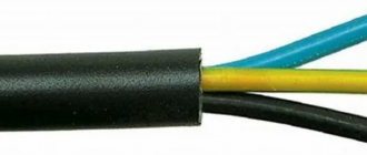
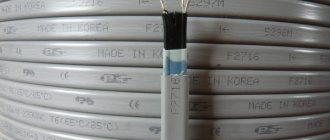
Characteristics you need to know when using metal corrugated pipes
- Inner diameter. May differ significantly from the outside: it depends on the shape of the profile. If you know the diameter of the outer sheath of the cable, you need to multiply this figure by 1.5 or 2. When laying two cables in a sleeve, the diameter is added up.
- Conditional pass. This is actually the minimum diameter of the coil profile, which is taken into account when selecting connecting and input couplings for corrugated pipes.
- Outer diameter - the maximum size of the coil wave, according to the outer coating (if any).
- The tightness class is either according to the “IP” standard system - international, or according to the domestic classification: P1, P2, P3. The higher the number, the worse the tightness and the lower the cost.
- The tightness depends on the material of the interturn seal. The conditions of use also depend on it. Cotton - internal installation in rooms with a non-aggressive environment. Asbestos - operation in fire hazardous conditions, or with local heating. Polypropylene - outdoor use, or rooms with direct exposure to liquids.
- Climate class. Indicated in the product passport. Must be taken into account when laying. There are quite a lot of varieties: about 50 options.
- Passage of interference both from inside the corrugation and inside the sleeve. The undisputed leader in this discipline is the accordion-type sleeve. But a helical corrugation can also serve as an excellent shield if it is grounded.
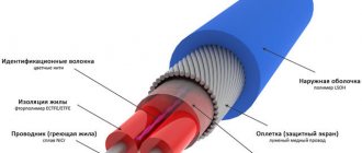
The main parameters and components of the metal hose in the illustration:
1. The main profile is a coil made of metal.
2. Sealing material sealing the interturn grooves.
3. Outer shell made of polyvinyl chloride.
D. Outer diameter - measured along the outer shell.
d. Conditional diameter (when selected according to the diameter of the cable to be laid - internal diameter).
Is it possible to lay a cable on the roof of a building according to the PUE?
Laying electrical wiring on the roofs of residential and public buildings, on the roofs of entertainment and entertainment enterprises, in accordance with the PUE, is not allowed (clause 2.1.75). The exception is when it comes to power supply inputs to buildings and branches to them. The rules use the “except” wording, from which it follows that the roof can still serve as a cable installation site when it comes to power input. However, paragraph 2.1.75. does not confirm this.
It is recommended (clause 2.1.79) that the entrance cable into the building be passed through the wall in a pipe (for more details, see the article: https://samelectrik.ru/kak-provesti-kabel-cherez-stenu.html). As a less desirable option, the roof of the house is used as the power input point. The cable must be in a steel pipe. The rule clause regulates the vertical distances between the roof and the wires. The minimum value of this distance prescribed by the PUE should be 2.5 meters. These conditions exclude the option in which a cable or wire is laid directly on the roof, that is, the roof cannot be used to lay a power line.
Important point! The effect of this chapter of the rules applies to wires or cables related to power or lighting networks with a voltage of up to 1000 Volts of direct or alternating current. This also refers to secondary circuits. If you are wondering whether it is possible to lay a heating conductor on the roof, the answer is yes, because... This is not prohibited by current rules. We talked in more detail about heating the roof and gutters in the corresponding article.
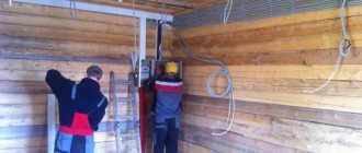
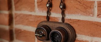
Installation of electrical networks on wooden walls
Today, both open and closed wiring are used for wooden surfaces. But despite the availability of these two methods, experts recommend using open wiring. The advantage of open wiring is associated with both safety and ease of access to any conductor. You can easily repair and replace electrical wiring, add new network elements.
The modern design of cable channels easily fits into the interior of any room, so open wiring looks quite aesthetically pleasing. Many network elements are specially designed for outdoor use; they come in different colors.
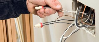
First, all the necessary elements are installed on a wooden surface - machines, chandeliers, switches, sockets, boxes. All of them are connected to each other by cable channels, into which electrical wires are subsequently laid.
What you need to consider when laying electrical networks on wooden walls:
- The brand of electrical wire must comply with the standards for laying on a wooden surface. They must be covered with non-combustible insulation;
- Only metal and tubular channels are used on wooden walls. Laying armored cable is also allowed. Corrugated plastic pipes are prohibited for installation on wooden walls;
- all metal channels are connected to each other with bolted fastenings;
- Tubular and metal channels are grounded.
Several examples of open wiring in a wooden house
GOST R 50571.5.52 requirements for external electrical wiring
Standard GOST R 50571.5.52-2011. “Low-voltage electrical installations. Part 5-52. Selection and installation of electrical equipment. Electrical wiring”, with a few exceptions, establishes requirements for electrical wiring without dividing them into internal and external.
We can highlight the most important requirements, which also apply to external electrical installations.
In accordance with 521.6 GOST R 50571.5.52:
– electrical wiring systems in pipes must comply with IEC 61386 (GOST R IEC 61386.1-2014 Pipe systems for laying cables. Part 1. General requirements is in force in Russia);
– electrical wiring systems in cable or special cable boxes - IEC 61084 (GOST R IEC 61084-1-2007 Cable and special cable boxes systems for electrical installations. Part 1. General requirements);
– electrical wiring systems on cable trays and cable ladders - IEC 61537 (GOST R 52868-2007 Cable tray systems and cable ladder systems for laying cables. General technical requirements and test methods).
Chapter 522 GOST R 50571.5.52 “Installation of electrical wiring under external influences” contains important requirements regarding the protection of electrical wiring from moisture, tensile forces on vertical sections of the route from its own weight, displacement of building structures and other mechanical influences.
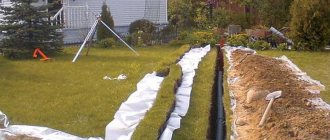
Types of electrical wiring for installation in the ground
Electrical networks come in different types and are classified according to their purpose and method of solving the tasks. It is possible to organize energy supply to a building not only by air, but also by ground. For comparison, the main options for laying wires in soil or water will be discussed below.
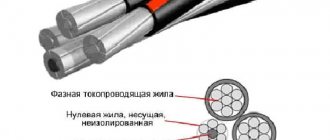
The most commonly used cables are the following types:
- armored VBBShV with three-layer insulation - suitable for laying in the ground and under the road surface (in the ground it can be replaced with VVG with two-layer insulation);
- armored SKLU, ASKLU, OSKU, AOSKU with a lead sheath, produced with copper and aluminum conductors - used for installation in reservoirs;
- well-known AAshv, AAshp, AVVG, AABL - suitable for soil with low corrosive activity;
- power AAB2l, ASB, ASPL - another ideal option for laying in soil with low corrosion activity;
- AAPl2Shv is suitable for soil with high corrosive activity;
- PvKShp with reinforced armor is often used in the northern regions of the country, where it is necessary to work with frozen soil.
Cable AAB2l 3x120 for underground installation
The best solution for laying an electrical line in the ground is an armored cable with several insulating layers, which has increased protection from mechanical influences and does not require additional protective equipment (corrugations, pipes). Wires of other brands acceptable for laying in the ground must be laid in polyvinyl chloride pipes.
If the cable is laid under the road, then trenches with a concrete floor will be needed. This is the only way to guarantee protection from mechanical damage. Certain standards are observed when moving the trench beyond the road boundary. In most cases, this process must be coordinated with road services.
In water, the cable is laid either manually or mechanically. The first option is suitable for shallow waters, the second involves the use of a special pontoon equipped with an electric cable on a drum. The pontoon moves from one bank to the other along a pre-tensioned cable; the cable slowly unwinds and sinks to the bottom, where divers lay it. We allow installation in winter from the icy surface of a reservoir.
Requirements of the GOST R 50571.5.51 standard
GOST R 50571.5.51-2013/IEC 60364-5-51:2005 “Low-voltage electrical installations. Part 5-51. Selection and installation of electrical equipment. General requirements".
At a minimum, this standard must take into account the following requirements:
512.2.1 Electrical equipment shall be selected and installed in accordance with the requirements of Table 51A, which specifies the required characteristics of electrical equipment appropriate to the external influences to which it may be subjected.
512.2.2 If the electrical equipment by its design does not meet the requirements that satisfy external influences at the installation site, then it can be used with the installation of appropriate additional protection when installing the electrical equipment. Such protection must not have a harmful effect on the functioning of the electrical equipment.
Construction company LLC “Artpaint”. Construction of engineering networks and communications
Crossing underground networks
In a modern city, intersections of underground networks are inevitable. The location of pipelines and cables at these intersections is determined by design, operational and sanitary requirements.
Structural requirements include the independence of settlement of different networks at the intersection under the influence of permanent and temporary loads. Based on this, one pipeline should not be allowed to directly rest on another, as this could result in fractures of the upper or lower pipeline.
To ensure independent settlement, the distance between the outer walls of the pipes should be about 15 cm.
According to operational and technical conditions, there must also be a certain distance between individual vertical communications, sufficient for the repair of individual networks.
In all cases of intersection of water pipes with gas pipelines and heat pipes, the vertical distance between them must be at least 0.15 m and in exceptional cases - 0.10 m. Water pipes can be passed through channels in which heat pipes are located.
It is recommended to lay water pipes at the intersection with sewer pipes higher than the latter, but in practice this is not always possible. Sewer pipes laid above water pipes at a length of 3-4 m must be metal (preferably cast iron) at the intersection.
If a medium-diameter sewerage system, consisting of ceramic or link concrete pipes, is laid above the water supply system, then at the intersection site the sewerage pipes should be embedded in concrete masses.
When crossing gas pipelines, heating pipelines or water pipelines at the same level with gravity sewers and drains on metal pressure pipelines, it is necessary to arrange contours near the gravity lines.
If a gas pipeline crosses a sewer or drainage collector, then in exceptional cases it is allowed to pass the gas pipeline through the collector. In this case, it is necessary to enclose the gas pipeline in a steel casing, the ends of which must be brought out at least 0.5 m from the outer surface of the collector walls, and there should be no pipe joints within the casing.
When drainage and sewer pipes intersect at the same level, a difference may be created on one of them, depending on local conditions. But in some cases, the differential device is inconvenient and uneconomical, especially on collectors. Therefore, a sewer pipe, as a permanent one, can be laid in the form of a siphon under a drain in compliance with all design requirements for siphons.
Underground networks when crossing tram tracks should be located at a depth of at least 1 m from the base of the rail to the top of the pipe or cable casing and laid at right angles or at least 75° to the track axes.
Typically, the normal depth of laying metal pipelines in order to reduce the influence of stray electric currents should be at least 1.5-2 m. In this case, the pipelines must have reliable coatings and be laid in a wooden or asbestos-cement case with bitumen filling the gap between the pipe and the case with a thickness of 25-20 m. 50 mm. The case must have a length of at least 2 liters from the outermost threads of the rail tracks.
When crossing power cables (as well as power cables with communication cables) laid directly into the ground, the distance between them must be at least 0.5 m. Communication cables should be located above the power cables. The required distance between pipelines and cables is 0.5 m. If for some reason this distance needs to be reduced, then the pipelines are separated from the cables by fire-resistant plates or the cables are enclosed in pipes. In this case, the vertical distance between communications is allowed to be at least 250 mm.
If there are a number of pipelines, cables and channels at street intersections, it is advisable to arrange underground chambers in which the intersection of all pipelines and control of the fittings installed on them are concentrated.
The design of these cameras is similar to cameras on combined collectors.
Special cases of laying electrical cables on the roof
Installation of an open electrical power cable on the roof with a cross-section of less than 16 mm² is unacceptable. Among the installation methods in clause 2.3 of the Rules, there is also no mention of installing wiring in excess of this norm. The above rule is valid for power lines with voltages up to 1,000 W.
At the same time, a low-voltage heating cable is quite acceptable and even necessary to use where ice forms. This will allow you not to damage the roof eaves, and most importantly, protect yourself from the involuntary melting of a large amount of snow. The load gradually increases, the snow block and icicles create a danger especially for people.
Recently, the possibilities of laying communication cables are limited by the capacity of internal channels. This results in an extensive web of wires from different providers on the roofs of multi-storey buildings. Their installation also has its own specifics.
Note: There are specifics to laying power cables in pitched roofs. This problem has one more aspect: the roof, like the roof, can be of different types, including pitched ones, made of flammable materials, such as wood. There is a difference between the concepts of roofing and roofing as a whole, since in the latter case the attic space of pitched roofs may also be implied.
After the electrical cable is introduced into the facility, it inevitably passes through the roof attic; it is reasonable to assume that the above rules also regulate the conditions for further installation.
This is a hotel specificity and we will not consider it here.
Let's just say that according to the rules, the cable must be in a protected fireproof sheath (metal hose) secured to metal clamps, and pass through the roof attic exclusively in the open.
Situations when you can’t do without a façade gasket
To the situations listed above, let’s add the simplest one: when organizing a power line over the air, a building stood in the way of the highway - an obstacle that can be overcome in two ways. Firstly, there is a more expensive option that involves going around the building (a lot of poles, cables and other devices will be required). Secondly, you can save a lot if you lay a line along the facade of the building. Several decades ago, the second was not available, since overhead power lines were created exclusively on bare wires.
External cable laying on the wall
Let's focus on solving problems in everyday life. Previously, during the construction of cottages and private houses in holiday villages, an unpleasant situation often arose: the main line ran on one side of the house, and the distribution panel was installed on the wall directed in the opposite direction. This usually ended with the installation of an additional pole. And often the object had to be dug in right on its own site.
Selecting a cable for roof heating
For heating purposes, a self-regulating and, less often, resistive type of cable is usually laid. Self-regulating is able to independently adjust the temperature of the heat it generates. By the way, for comparison, the amount of energy released by a resistive cable is in the range of 5–30 W, and a self-regulating one is capable of delivering from 6 to 100 W per meter of roof area.
Self-regulating cable structure
Marking of the roof passage unit
The modern construction market is ready to provide 11 types of ventilation passage units with different sizes. However, in some cases their manufacture requires a non-standard approach.
In the marking of passage units, the main designations are the letters “UP”, as well as numbers from 1 to 10, meaning that the units do not have an element that collects condensate, as well as a valve.
A series of numbers from 2 to 10 indicates that the passage has a valve in its design that operates using manual control, but does not have a condensate ring. The designations “UPZ-UPZ-21” indicate that the passage unit is equipped with all elements: manual control, valve, condensate ring.
We start dancing from the façade wall
First of all, you need to select a point on the wall from which the branch will begin. The rules for electrical installations do not regulate the choice of wall: it can be front or side. But in practice, in our latitudes it is the façade that is chosen. Roof slopes usually extend onto the side walls of buildings, from which ice (icicles) or snow can fall off.
The starting point for laying on the wall is considered to be the point where the cable exits the anchor clamp. The main design elements are shown in the illustration:
- Anchor bracket.
- An anchor clamp, after which the wire is not held on the overhead line route.
- Facade fastening is the first element of the wall installation system.
The bracket is installed at a height of at least 2.75 meters. The distance to the nearest corner of the load-bearing wall (excluding the thickness of the insulating material) is at least 10 cm.
Options for installing roof penetrations
Today, manufacturers produce passage units of various types:
- equipped with a valve;
- without valves;
- equipped with insulation;
- without insulation;
- equipped with technology that controls the opening and closing of valves.
Units that have manual control in their design are usually used where there is no need to regularly use multiple ventilation modes. The manual control unit includes:
- tailor's cloth;
- counterweight;
- cable;
- management sector.
A special mechanism helps control the valve, which regulates the position of the valve through two main commands - “open” and “closed”. To create penetrations for the roof, manufacturers use a black sheet of metal, the thickness of which does not exceed 2 millimeters, as well as a sheet of stainless steel, having a thickness of 0.5 to 0.8 millimeters.
The production of the passage unit can also be carried out on the basis of galvanized steel along with insulation, which is most often represented by a layer of mineral wool 50 millimeters thick. This option involves installing umbrellas or deflectors treated with zinc in the system. When installed on a fan assembly, its internal structure can be made of perforated steel and equipped with electrically conductive plastic tubes. With this installation method, the passage unit will also perform a soundproofing function.
Fastening principles
The method of attaching the heating cable to the roof is dictated by the type of roof covering material. It is recommended to give preference to types of fasteners that do not violate the integrity of the roof deck
.
A common fastening element is the SLT-C clip, which is installed using a screw or nail. Construction silicone sealant is used to waterproof the resulting hole. In addition, mastics or fasteners with an adhesive layer can be used.
Metal ribbed roofing allows the use of SLT-C clips for cable installation, which are attached to the edges of the covering. If the roof is flat, the heating wire is mounted on the mesh using clips and bolts with nuts, and then the entire structure is glued to the surface.
Installation of the cable on a tiled roof requires the use of perforated fastening tape, which is laid on glue with a 75 mm overlap under the previous row of tiles. Attaching the heating cable to a soft roof can be done using clips, but it is recommended to use adhesive aluminum tape: a piece of tape is glued to the covering, the cable is laid across it and secured on top with a second piece of tape. You can also install heating threads in gutters and in places exposed to wind.
Fastening in valleys is carried out using tensioned cables, or it is glued to the roofing material - the tightness of this roofing element must not be violated. To suspend the cable in the gutter system, the SLT-D kit is used - it must be fixed to the roof or gutter. When laying one heating thread, the end of the cable is bent upward approximately half a meter and then secured with a tie.
If the pitched roof is not equipped with a gutter and icicles form on the edge during thaws, the instructions allow you to run the cable under the edge of the roof - heating will “cut off” the icicles as they form.