SMD resistors for surface mounting have three main characteristics: element size (standard size), resistance in Ohms, resistance tolerance in percentage. The standard size is indicated by a four-digit number. Below is a table of common sizes and their geometric dimensions.
| 1.00 | 0.50 | 0.20 | 0.25 | |
| 0603 | 1.60 | 0.85 | 0.30 | 0.30 |
| 0805 | 2.10 | 1.30 | 0.40 | 0.40 |
| 1206 | 3.10 | 1.60 | 0.50 | 0.50 |
| 1210 | 3.10 | 2.60 | 0.50 | 0.40 |
| 2010 | 5.00 | 2.50 | 0.60 | 0.40 |
| 2512 | 6.35 | 3.20 | 0.60 | 0.40 |
Online SMD resistor calculator
This calculator will help you determine the resistance of SMD resistors . Just enter the code written on the resistor and its resistance will be reflected below.
The calculator can be used to determine the resistance of SMD resistors that are marked with 3 or 4 numbers, as well as according to the EIA-96 standard (2 numbers + letter).
Although we have done our best to test the function of this calculator, we cannot guarantee that it calculates the correct values for all resistors as manufacturers may sometimes use their own custom codes.
Therefore, to be absolutely sure of the resistance value, it is best to additionally measure the resistance using a multimeter.
Thermistors sizes 0805 and 0603
| NTC Thermistors EWTF05 Rating: 10 kOhm, 22 kOhm, 47 kOhm, 100 kOhm. | NTC Thermistors EWTF03 Rating: 10 kOhm, 22 kOhm, 47 kOhm, 100 kOhm. |
Resistance marking of SMD resistors of the E24 series with a nominal deviation of 5%
| Marker. | Denomination | I | Marker. | Denomination | I | Marker. | Denomination | I | Marker. | Denomination |
| 0 | 0 ohm | I | I | I | ||||||
| 1R0 | 1 ohm | I | 101 | 100 Ohm | I | 102 | 1kOhm | I | 104 | 100kOhm |
| 1R1 | 1.1 ohm | I | 111 | 110 Ohm | I | 112 | 1.1kOhm | I | 114 | 110kOhm |
| 1R2 | 1.2 ohm | I | 121 | 120 Ohm | I | 122 | 1.2kOhm | I | 124 | 120kOhm |
| 1R3 | 1.3 ohm | I | 131 | 130 Ohm | I | 132 | 1.3kOhm | I | 134 | 130kOhm |
| 1R5 | 1.5 ohm | I | 151 | 150 Ohm | I | 152 | 1.5kOhm | I | 154 | 150kOhm |
| 1R6 | 1.6 ohm | I | 161 | 160 Ohm | I | 162 | 1.6kOhm | I | 164 | 160kOhm |
| 1R8 | 1.8 ohm | I | 181 | 180 Ohm | I | 182 | 1.8kOhm | I | 184 | 180kOhm |
| 2R0 | 2.0 ohm | I | 201 | 200 Ohm | I | 202 | 2.0kOhm | I | 204 | 200kOhm |
| 2R2 | 2.2 ohm | I | 221 | 220 Ohm | I | 222 | 2.2kOhm | I | 224 | 220kOhm |
| 2R4 | 2.4 ohm | I | 241 | 240 Ohm | I | 242 | 2.4kOhm | I | 244 | 240kOhm |
| 2R7 | 2.7 ohm | I | 271 | 270 Ohm | I | 272 | 2.7kOhm | I | 274 | 270kOhm |
| 3R0 | 3.0 ohm | I | 301 | 300 Ohm | I | 302 | 3.0kOhm | I | 304 | 300kOhm |
| 3R3 | 3.3 ohm | I | 331 | 330 Ohm | I | 332 | 3.3kOhm | I | 334 | 330kOhm |
| 3R6 | 3.6 ohm | I | 361 | 360 Ohm | I | 362 | 3.6kOhm | I | 364 | 360kOhm |
| 3R9 | 3.9 ohm | I | 391 | 390 Ohm | I | 392 | 3.9kOhm | I | 394 | 390kOhm |
| 4R3 | 4.3 ohm | I | 431 | 430 Ohm | I | 432 | 4.3kOhm | I | 434 | 430kOhm |
| 4R7 | 4.7 ohm | I | 471 | 470 Ohm | I | 472 | 4.7kOhm | I | 474 | 470kOhm |
| 5R1 | 5.1 Ohm | I | 511 | 510 Ohm | I | 512 | 5.1kOhm | I | 514 | 510kOhm |
| 5R6 | 5.6 ohm | I | 561 | 560 Ohm | I | 562 | 5.6kOhm | I | 564 | 560kOhm |
| 6R2 | 6.2 ohm | I | 621 | 620 Ohm | I | 622 | 6.2kOhm | I | 624 | 620kOhm |
| 6R8 | 6.8 ohm | I | 681 | 680 Ohm | I | 682 | 6.8kOhm | I | 684 | 680kOhm |
| 7R5 | 7.5 ohm | I | 751 | 750 Ohm | I | 752 | 7.5kOhm | I | 754 | 750kOhm |
| 8R2 | 8.2 Ohm | I | 821 | 820 Ohm | I | 822 | 8.2kOhm | I | 824 | 820kOhm |
| 9R1 | 9.1 Ohm | I | 911 | 910 Ohm | I | 912 | 9.1kOhm | I | 914 | 910kOhm |
| 10R(100) | 10 ohm | I | 102 | 1kOhm | I | 103 | 10kOhm | I | 105 | 1MOhm |
| 11R(110) | 11 ohm | I | 112 | 1.1kOhm | I | 113 | 11kOhm | I | 115 | 1.1 MOhm |
| 12R(120) | 12 ohm | I | 122 | 1.2kOhm | I | 123 | 12kOhm | I | 125 | 1.2 MOhm |
| 13R(130) | 13 ohm | I | 132 | 1.3kOhm | I | 133 | 13kOhm | I | 135 | 1.3 MOhm |
| 15R(150) | 15 ohm | I | 152 | 1.5kOhm | I | 153 | 15kOhm | I | 155 | 1.5 MOhm |
| 16R(160) | 16 ohm | I | 162 | 1.6kOhm | I | 163 | 16kOhm | I | 165 | 1.6 MOhm |
| 18R(180) | 18 ohm | I | 182 | 1.8kOhm | I | 183 | 18kOhm | I | 185 | 1.8 MOhm |
| 20R(200) | 20 ohm | I | 202 | 2.0kOhm | I | 203 | 20kOhm | I | 205 | 2.0 MOhm |
| 22R(220) | 22 Ohm | I | 222 | 2.2kOhm | I | 223 | 22kOhm | I | 225 | 2.2 MOhm |
| 24R(240) | 24 ohm | I | 242 | 2.4kOhm | I | 243 | 24kOhm | I | 245 | 2.4 MOhm |
| 27R(270) | 27 Ohm | I | 272 | 2.7kOhm | I | 273 | 27kOhm | I | 275 | 2.7 MOhm |
| 30R(300) | 30 ohm | I | 302 | 3.0kOhm | I | 303 | 30kOhm | I | 305 | 3.0 MOhm |
| 33R(330) | 33 Ohm | I | 332 | 3.3kOhm | I | 333 | 33kOhm | I | 335 | 3.3 MOhm |
| 36R(360) | 36 Ohm | I | 362 | 3.6kOhm | I | 363 | 36kOhm | I | 365 | 3.6 MOhm |
| 39R(390) | 39 Ohm | I | 391 | 390 Ohm | I | 393 | 39kOhm | I | 395 | 3.9 MOhm |
| 43R(430) | 43 Ohm | I | 431 | 430 Ohm | I | 433 | 43kOhm | I | 435 | 4.3 MOhm |
| 47R(470) | 47 Ohm | I | 471 | 470 Ohm | I | 473 | 47kOhm | I | 475 | 4.7 MOhm |
| 51R(510) | 51 Ohm | I | 511 | 510 Ohm | I | 513 | 51kOhm | I | 515 | 5.1 MOhm |
| 56R(560) | 56 Ohm | I | 561 | 560 Ohm | I | 563 | 56kOhm | I | 565 | 5.6 MOhm |
| 62R(620) | 62 Ohm | I | 621 | 620 Ohm | I | 623 | 62kOhm | I | 625 | 6.2 MOhm |
| 68R(680) | 68 Ohm | I | 681 | 680 Ohm | I | 683 | 68kOhm | I | 685 | 6.8 MOhm |
| 75R(750) | 75 Ohm | I | 751 | 750 Ohm | I | 753 | 75kOhm | I | 755 | 7.5 MOhm |
| 82R(820) | 82 Ohm | I | 821 | 820 Ohm | I | 823 | 82kOhm | I | 825 | 8.2 MOhm |
| 91R(910) | 91 Ohm | I | 911 | 910 Ohm | I | 913 | 91kOhm | I | 915 | 9.1 MOhm |
| 106 | 10MOhm |
Resistors, or resistors, as well as capacitors, are the most common components of electronic circuits. Surface mount resistors are manufactured by applying resistive paste to a ceramic substrate and then sintering it under high temperatures. On the surface of the resistor, the resistance value is usually indicated in the symbol. To increase power dissipation and improve stability of performance, the ceramic base can be replaced with a metal one. SMD resistors are designed for automatic installation and soldering by reflowing solder paste in the vapor-gas phase of an infrared heating oven. Resistors are packaged in blister tape, which in turn is wound on a plastic reel.
Along with a wide range of passive components: resistors, capacitors, inductors, chokes, connectors, switches, the company supplies active components from stock: SMD transistors, SMD diodes, zener diodes, LEDs, microcircuits.
SMD resistors
SMT technology (from the English Surface Mount Technology) was developed with the aim of reducing the cost of production, increasing the efficiency of manufacturing printed circuit boards using smaller electronic components: resistors, capacitors, transistors, etc. Today we will look at one of these types of resistors - the SMD resistor.
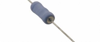
SMD resistors are miniature resistors designed for surface mounting. SMD resistors are significantly smaller than their traditional counterpart. They are often square, rectangular or oval shaped, with a very low profile.
Instead of the lead wires of conventional resistors that are inserted into holes on a printed circuit board, SMD resistors have small contacts that are soldered to the surface of the resistor body. This eliminates the need to make holes in the printed circuit board, and thus allows more efficient use of its entire surface.
Characteristics
These miniature resistors are perfect for surface mounting. Marking allows you to find out the size, power and resistance of the product.
The shape of SMD resistors is rectangular, square, round, oval, the profile is low. Low-profile elements are placed on the board very compactly and significantly save usable space.
SMD resistors are classified according to a number of parameters, such as:
- Nominal resistance
. This value is measured under certain environmental parameters, the most important of which is temperature. Usually the nominal resistance is considered to be measured at a temperature of +20 °C and normal atmospheric pressure. - Tolerance on nominal resistance
. Possible tolerances are from 0.05 to +5%. The most popular and affordable parts with tolerances of +/-1% and +/-5%. More accurate models must be pre-ordered, and they are much more expensive than less accurate analogues. - Temperature coefficient of resistance change (TCC)
. This parameter characterizes the reversible relative change in the resistance of the part when the temperature fluctuates by 1 °C. Temperature changes in the part are possible due to changes in ambient temperature or self-heating of the resistor. The unit of measurement for this value is ppm. Modern SMD resistors are produced with TCR, the value of which is in the range of +/-5...+/-200 ppm. If parts from the same manufacturer are used to create a circuit, then the values of their nominal resistances and TCR are closer to each other than is reflected in the passport for each part. Therefore, using parts from the same manufacturer allows you to improve the accuracy of the circuit both at a constant temperature and when it changes. - Power dissipation
. This parameter depends on the size and is determined from the table.
SMD resistor sizes
Basically, the term frame size includes the size, shape and terminal configuration (package type) of any electronic component. For example, the configuration of a conventional chip that has a flat package with double-sided pins (perpendicular to the plane of the base) is called DIP.
SMD resistor sizes are standardized, and most manufacturers use the JEDEC standard. The size of SMD resistors is indicated by a numerical code, for example, 0603. The code contains information about the length and width of the resistor. So in our example code 0603 (in inches) the body length is 0.060 inches by 0.030 inches wide.
The same resistor size in the metric system will have code 1608 (in millimeters), respectively, the length is 1.6 mm, the width is 0.8 mm. To convert dimensions to millimeters, simply multiply the size in inches by 25.4.
SMD resistor sizes and their power
The size of the SMD resistor depends mainly on the required power dissipation. The following table lists the case sizes and power of smd resistors most commonly used in practice, namely smd resistors 0201, 0420, 0603, 0805, 1206, 1210, 1218, 2010 and 2512 :
Therefore, based on the table above, based on the size of the case, you can determine the power of the SMD resistor .
Surface Mount Resistor Assemblies
| Resistor assemblies 0804 TC124 4 resistors with nominal values: 22 Ohm, 33 Ohm, 51 Ohm, 220 Ohm, 1 kOhm, 4.7 kOhm, 10 kOhm. Power 0.0625 W. |
Surface Mount Trimmer Resistors
| Trimmer potentiometers Nidec ST32 Rating: 500 Ohm, 1 kOhm, 5 kOhm, 10 kOhm, 50 kOhm, 100 kOhm. Power 0.125 W. | Trimmer potentiometers Murata PVZ3A Rating: 200 Ohm, 500 Ohm, 1.5 kOhm, 2 kOhm, 10 kOhm, 15 kOhm, 20 kOhm, 50 kOhm, 100 kOhm, 500 kOhm, 1 mOhm, Power 0.1 W. |
Marking of SMD resistors
Due to the small size of SMD resistors, it is almost impossible to apply traditional resistor color coding to them.
In this regard, a special marking method has been developed that allows one to determine one or another value of an SMD resistor . The most common marking contains three or four numbers, or two numbers and a letter, called EIA-96. The following is a breakdown of SMD resistors .
Marking with 3 and 4 digits
In this system, the first two or three digits indicate the numerical value of the resistor, and the last digit indicates the multiplier. This last digit indicates the power to which 10 must be raised to obtain the final factor.
A few more examples of determining resistance within this system:
- 450 = 45 x 100 equals 45 ohms
- 273 = 27 x 103 equals 27000 ohms (27 kohms)
- 7992 = 799 x 102 equals 79900 ohms (79.9 kohms)
- 1733 = 173 x 103 equals 173000 ohms (173 kohms)
The letter “R” is used to indicate the position of the decimal point for resistance values below 10 ohms. Thus, 0R5 = 0.5 ohms and 0R01 = 0.01 ohms.
Three-digit resistor numbering with 1% tolerance
Resistors with a tolerance of 1% of size 0603 are marked using three-digit numbering. The first two characters are numbers indicating the resistance value in Ohms, taken from the table below. The last character is a letter indicating the value of the multiplier: S=0.1; R=1; B=10; C=100; D=1000; E=10000; F=100000. For example, the marking 28C means that the resistor has a value of 191 × 100 ohms = 19.1 kOhms.
| = 19.1 KOhm |
| Code | Meaning | Code | Meaning | Code | Meaning | Code | Meaning |
| 01 | 100 | 25 | 178 | 49 | 316 | 73 | 562 |
| 02 | 102 | 26 | 182 | 50 | 326 | 74 | 576 |
| 03 | 105 | 27 | 187 | 51 | 332 | 75 | 590 |
| 04 | 107 | 28 | 191 | 52 | 340 | 76 | 604 |
| 05 | 110 | 29 | 196 | 53 | 348 | 77 | 619 |
| 06 | 113 | 30 | 200 | 54 | 357 | 78 | 634 |
| 07 | 115 | 31 | 205 | 55 | 365 | 79 | 649 |
| 08 | 118 | 32 | 210 | 56 | 374 | 80 | 665 |
| 09 | 121 | 33 | 215 | 57 | 383 | 81 | 681 |
| 10 | 124 | 34 | 221 | 58 | 392 | 82 | 698 |
| 11 | 127 | 35 | 226 | 59 | 402 | 83 | 715 |
| 12 | 130 | 36 | 232 | 60 | 412 | 84 | 732 |
| 13 | 133 | 37 | 237 | 61 | 422 | 85 | 750 |
| 14 | 137 | 38 | 243 | 62 | 432 | 86 | 768 |
| 15 | 140 | 39 | 249 | 63 | 442 | 87 | 787 |
| 16 | 143 | 40 | 255 | 64 | 453 | 88 | 806 |
| 17 | 147 | 41 | 261 | 65 | 464 | 89 | 825 |
| 18 | 150 | 42 | 267 | 66 | 475 | 90 | 845 |
| 19 | 154 | 43 | 274 | 67 | 487 | 91 | 866 |
| 20 | 158 | 44 | 280 | 68 | 499 | 92 | 887 |
| 21 | 162 | 45 | 287 | 69 | 511 | 93 | 909 |
| 22 | 165 | 46 | 294 | 70 | 523 | 94 | 931 |
| 23 | 169 | 47 | 301 | 71 | 536 | 95 | 953 |
| 24 | 174 | 48 | 309 | 72 | 549 | 96 | 976 |
Resistance tolerances
As you may have already noticed, in all three coding systems that we studied, the manufacturers did not provide any way to indicate the tolerance (deviation) of the resistor resistances (the fourth colored stripe as on the output resistors).
But as a rule, resistors with 3-digit markings have an accuracy of 5%, and resistors with a 4-digit code, as well as resistors with EIA-96 coding, have an accuracy of 1%.
2W resistors with a resistance of less than 0.01 Ohm
| 0.001Ω ± 1% | ±50 ppm/°C | 2 W | LR2512-22 R001 F2 | |
| 2512 | 0.005Ω ± 1% | ±25 ppm/°C | 2 W | LR2512-22 R005 F4 |
| 2512 | 0.01Ω ± 1% | ±15 ppm/°C | 2 W | LR2512-22 R010 F2 |
| 2512 | 0.025Ω ± 2% | ±15 ppm/°C | 2 W | LR2512-FMF25GPJR025 |
| 2512 | 0.05Ω ± 1% | ±15 ppm/°C | 2 W | LR2512-22 R050 F4 |
Packaging: In blister tape on a reel with a diameter of 180 mm, 2000 pieces LR2512
Four-digit code (precision resistors)
In the case of precision resistors, manufacturers have created another coding system consisting of 4-digit numbers. In it, the first three digits are the numerical value, and the fourth digit is the multiplier, that is, the number of zeros that we must add to the value.
The fact of having three digits to encode a value allows us to have greater variety and precision of meaning.

