Installation of electrical wiring in a building (residential or industrial) is carried out in two ways - hidden or open; the electrical wiring itself can be permanent or replaceable. Hidden installation of electrical wiring and its fastening in concrete is considered the most difficult option due to the strength of the building material and the restrictive conditions for laying grooves in panel houses. But even under favorable installation conditions, it will not be possible to install a hidden line in every building. Thus, a wooden house is not intended for such installation, and it is not allowed to lay grooves in a single facing brick, so as not to damage the decorative surfaces of the product - wiring under plaster must be implemented without grooves.
Rules for installing hidden electrical wiring
According to the rules for electrical installations (PUE) and building codes (SNiP), in internal residential premises, power supply lines for household equipment, appliances and devices are laid with copper cable in non-flammable or fire-resistant insulation. Aluminum does not withstand heavy loads, although previously only aluminum internal lines were used.
PUE and SNiP allow the laying of electrical cables of the following sections:
- Supply cable to the switchboard - brand VVG-2, cross-section 6 mm2 or brand VVG-5, cross-section 6 mm2;
- Laying wires around the apartment and connecting electrical sockets - brand VVG-3, cross-section 2.5 mm2;
- The supply to electrical switches and lighting devices is VVG-3 brand, cross-section 1.5 mm2.
Also, when laying an internal electrical network, the best option for connecting electrical outlets is a VVG cable with a cross-section of 2.5 mm2, and for laying lighting networks - a PUGNP wire with a cross-section of 1.5 mm2. For rooms with high humidity, it is recommended to mount PVA grade wire.
The question of when to do wiring before or after plastering is easily resolved - if gating is necessary, then first lay the electrical lines, after which the plaster layer is applied.
What can be used from special fittings
In fact, the problem of extension cords and cables collecting dust under office desks and cabinets is not new. To hide the wires from the computer and all the office equipment connected to it, there is no need to reinvent the wheel. It is enough to study the range of furniture accessories of any large specialized store. And you can choose several options. With the help of special devices, entire “highways” are created that are accessible for maintenance and do not interfere with everyday life.
For example, the MDM kit contains such fastenings for wires.
And baskets for power blocks (sources), blocks of mortise sockets and plugs of various sizes for decorating countertops.
There are many manufacturers and the range is really wide, for different price categories.
Requirements for the number of wire cores
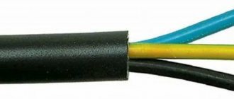
Electrical installation in residential buildings and premises is carried out with a copper cable of three cores. One wire is phase, the second wire is zero, the third wire is grounding.
2 options for grounding wiring have been developed, and they differ from each other in the point of separation of the neutral wire:
- TN-S - separation of the working neutral wire (N);
- TN-CS - separation of the protective neutral conductor (PE).
The grounding wire is designed to protect against electric shock and protect household appliances from failure. When laying wiring, the grounding must have reliable terminal connections. Correct installation of electrical wiring requires that twisting wires together and using bolted connections is strictly prohibited by the PUE and SNiP. In addition to terminals, soldered wiring connections are permitted. A typical installation of electrical wiring in a brick house requires that soldered or terminal connections are hidden in distribution boxes, in glasses for mounting sockets, or in distribution boards with free access.
It is recommended to replace old aluminum wires with copper wiring. If it is not possible to replace aluminum with copper, connecting wiring from different materials is allowed only at terminals.
If you don’t know how to connect wires under plaster, then there is only one answer - waterproof terminals.
Mounting method
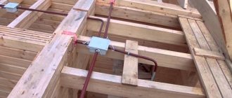
When laying without corrugation, the cable is usually secured with ties, or the dowel is secured with clamps containing these same ties.
By securing it in this way, you influence it mechanically in any way. If at first glance nothing seems to happen to it, then over time, this method of fastening can play a cruel joke on you.
Even without using ties, but using special expensive fasteners, you still make the cable sag under its own weight.
Such fasteners negatively affect its insulation. This is not a SIP, which was originally manufactured taking into account sagging under its own weight.
And this, in a few years, will certainly lead to false alarms of the differential protection.
As you can see, all the methods that are presented by installers as simple and fast do not really fit into the definition of “durable installation”.
Installation of hidden electrical wiring: rules and sequence
Wiring is laid in a brick house in stages, and the first step is to develop a layout of the premises and select a connection option. Drawings or sketches of the plan must include a detailed description of the work to be done. For each room, a separate drawing is drawn up with a layout of the walls and a wiring diagram.
Important rules for laying wires:
- A distance of ≥ 150 mm is maintained from the wiring to the floor or ceiling surface, from a window or door ≥ 100 mm, from the heating system pipes ≥ 30 mm;
- Electrical wires are laid strictly vertically or horizontally - tilting at any other angle is strictly prohibited;
- Wiring in a brick house, and even more so in a wooden building, should not intersect; lines overlapping each other is unacceptable.
Fasteners on the back side of tabletops, tables or TV stands
As is clear from the range of devices offered, there are two ways to attach computer wires to the back of the tabletop:
- With double-sided tape. Not always reliable, but at least modelable.
- Self-tapping screws. The main thing is to use the “correct” screws, no longer than the thickness of the tabletop. As a rule, 3.5x16.
It is not always acceptable to make holes in the tabletop itself or the stiffener of the table. And it’s inconvenient if the workplace is already assembled and in its place. Therefore, a perforated screen is often used as a basis for attaching cables and power supplies.
Or a metal mesh shelf of suitable width and depth. This option is more expensive, but much stronger and more durable.
Using the same harnesses and clamps, the wires with all accessories are attached to the base. And only then, after the final “assembly” - to the back side of the tabletop or stiffener. It's much more convenient.
Main characteristics of wires
Reliable fastening of the wire to the wall under plaster depends on the properties of the cable or wire. Electric wire under plaster brand and some other distinctive characteristics:
- Section in mm2 –0.75-8.00;
- Material - Cu, Al and their alloys;
- According to the number of cores, wiring under plaster can consist of 1-37 single wires;
- The wiring on the shell before or after plastering can be plastic, rubber or even steel;
- According to the type of insulation, electrical insulation before or after plastering is made from cellulose, plastic, silicone, polymers, rubber.
What is the difference between a cable under plaster and wiring - wires have outer insulation made of thinner and softer material. The retail cost of wire for plaster will be lower than the price for cable. But the cable lasts longer, and this is its main advantage.
The decoding of the brand of wire or cable contains their properties, parameters and quality indicators. The first Cyrillic character means the core material. For example, “A” is a wire or cable made of aluminum (Al). Copper (Cu) wires are not marked. The remaining symbols in the cable or wire brand indicate the parameters and properties of other elements.
High-quality electrical installations, before or after plastering, must consist of two protected layers of insulation. Typical cable laying in the wall of a residential building or in an apartment is carried out in the same way as installing wires.
External camouflage
If they have an artistic taste, many people prefer to decorate rather than hide the wires. From standard wiring it is quite possible to make a real art object, painting, panel with your own hands. Typically, cables come in black or white, but if desired, you can find a material of a brighter shade.
Next, you should choose a drawing that suits the style of the interior, sketch it with a non-greasy pencil directly on the wall. Afterwards, you need to measure the length of the circuit using a thread in order to purchase the missing amount of cable (part of it will only serve a decorative role).
You can make any wall pattern out of wires. Often the following are taken as a basis:
- branch with leaves, sitting birds;
- one or more trees;
- giant light bulb;
- power station;
- highway (in the nursery);
- decorative fence.
The wires are attached to the wall with special fasteners, which can then be decorated with any suitable material - fabric, special paper, designer decorations. Also, unsightly protruding wires are hidden behind tall indoor plants, well-placed furniture, carpeting, door frames, and windows.
Selection of wire cross-section
An incorrect choice of wiring cross-section can lead not only to an overload in the general network, but also to a fire in the local overload area, which often means overheating of the wiring. The tables in this section will help you correctly determine the cross-section and select the type of wiring depending on the loads and characteristics of the wires.
| Number of cores and cross-section | Class | ⌀ with insulation in mm | ⌀ with shell in mm | Ωmin (Ohm) with a wire length of 1.0 km and t = 20°C | Coil length in meters | Wire weight (kg/km) | Dmin bending in mm |
| 3 x 4 | I | 3.73 | 11.62 | 4.61 | 100.0 | 235.19 | 7,5 |
| 3 x 6 | I | 4.22 | 12.67 | 3.08 | 100.0 | 305.92 | 7,5 |
| 3 x 10 | I | 5.46 | 15.34 | 1.83 | bar | 475.30 | 7,5 |
| 3 x 16 | II | 7.02 | 18.69 | 1.15 | bar | 724.59 | 7,5 |
| 4 x 1.5 | I | 2.67 | 10.03 | 12.1 | 100.0 | 153.33 | 7,5 |
| 4 x 2.5 | I | 3.05 | 10.95 | 7.41 | 100.0 | 201.75 | 7,5 |
| 4 x 4 | I | 3.73 | 12.59 | 4.61 | 100.0 | 285.59 | 7,5 |
| 4 x 6 | I | 4.22 | 13.77 | 3.08 | 100.0 | 375.54 | 7,5 |
| 4 x 10 | I | 5.46 | 16.76 | 1.83 | bar | 588.92 | 7,5 |
| 4 x 16 | II | 7.02 | 20.52 | 1.15 | bar | 902.80 | 7,5 |
| 5 x 1.5 | I | 2.67 | 10.81 | 12.1 | 100.0 | 178.58 | 7,5 |
| 5 x 2.5 | I | 3.05 | 11.84 | 7.41 | 100.0 | 237.36 | 7,5 |
| 5 x 4 | I | 3.73 | 13.67 | 4.61 | 100.0 | 338.80 | 7,5 |
| 5 x 6 | I | 4.22 | 14.99 | 3.08 | 100.0 | 448.59 | 7,5 |
| 5 x 10 | I | 5.46 | 18.34 | 1.83 | bar | 707.92 | 7,5 |
| 4 x 16 | II | 7.02 | 22.55 | 1.15 | bar | 1089.41 | 7,5 |
Using the data in the table, you can quickly calculate the wiring cross-section in mm2, based on the maximum load current values:
| Open laying scheme | Section in mm | Closed routing scheme | ||||||||||
| Cu | Al | Cu | Al | |||||||||
| I (A) | P (kW) | I (A) | P (kW) | I (A) | P (kW) | I (A) | P (kW) | |||||
| 220 V | 380 V | 220 V | 380 V | 220 V | 380 V | 220 V | 380 V | |||||
| 11 | 2.4 | — | — | — | — | 0.5 | — | — | — | — | — | — |
| 15 | — | — | — | — | 0.75 | — | — | — | — | — | — | |
| 17 | 3.7 | 6.4 | — | — | — | 1.0 | 14 | 3.0 | 5.3 | — | — | — |
| 23 | 5.0 | 8.7 | — | — | — | 1.5 | 15 | z.z | 5.7 | — | — | — |
| 26 | 5.7 | 9.8 | 21 | 4.6 | 7.9 | 2.0 | 19 | 4.1 | 7.2 | 14 | 3.0 | 5.3 |
| 30 | 6.6 | 11 | 24 | 5.2 | 9.1 | 2.5 | 21 | 4.6 | 7.9 | 16 | 3.5 | 6.0 |
| 41 | 9.0 | 15 | 32 | 7.0 | 12 | 4.0 | 27 | 5.9 | 10 | 21 | 4.6 | 7.9 |
| 50 | 11 | 19 | 39 | 8.5 | 14 | 6.0 | 34 | 7.4 | 12 | 26 | 5.7 | 9.8 |
| 80 | 17 | 30 | 60 | 13 | 22 | 10 | 50 | 11 | 19 | 38 | 8.3 | 14 |
| 100 | 22 | 38 | 75 | 16 | 28 | 16 | 80 | 17 | 30 | 55 | 12 | 20 |
| 140 | 30 | 53 | 105 | 23 | 39 | 25 | 100 | 22 | 38 | 65 | 14 | 24 |
| 170 | 37 | 64 | 130 | 28 | 49 | 35 | 135 | 29 | 51 | 75 | 16 | 28 |
Induced voltage
Induced voltage is a faithful companion of bundles of wires. It can negatively affect the operation of inexpensive LED lamps, causing backlighting or flickering.
In this case, an inexperienced user will have to call a specialist to deal with a phenomenon that is incomprehensible to him. And for every call you have to pay.
Although, of course, you can try to delve deeply into the problem and figure it out yourself.
Therefore, having saved once on corrugation from one master, get ready to pay others in the future, or spend money on alterations and independent modernization.
Types of terminations
The connection can be boxed or daisy-chained:
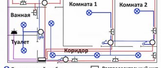
- The box type connection has a simple solution - the cable runs through all the rooms of the apartment, and in each individual room, through a junction box (junction box), wires for electricity distribution points, switches and lighting fixtures are routed from the cable. When implementing this connection option, the cost of purchasing wiring is minimal, and this is the main advantage of the method. The disadvantage of this scheme is that there is no physical possibility to control individual local sections of the internal electrical network from an external switchboard;
- Daisy chain wiring is a more modern option, which is why it is often called European. The essence of the scheme is that two cables are supplied from the external switchboard to each individual room: one for connecting lighting devices, the second for distribution points. Each cable is insured by connection through an RCD installed in the panel. The wire consumption when disconnecting with a loop is greater than in the first option, but much safer. Also, daisy chain connection allows for control and monitoring of the internal electrical network.
Camouflage covers
You can make your own cover for one or several cords at the same time from plastic bags cut into long, narrow strips. A kind of “sleeve” is knitted or crocheted from them, into which all the necessary wiring is inserted. To hide an extension cord with charges in this way, a handbag of suitable size is knitted or sewn.
Some stores offer decorative collapsible plastic covers in the form of tree branches, colored tubes, and shiny snakes. This design does not have the protective properties of cable ducts, but it is acceptable to cover “ugly” wires with it. If desired, a special spiral braid can be purchased - it is flexible, has an aesthetic appearance, and allows you to hide both one element and many wires.
Line layout diagrams
The principle of wiring power lines is simple - the higher the load, the thicker the wire or cable should be. At the entrance to the apartment, the cable must have the largest cross-section, since the entire apartment load falls on it. For branches to distribution points and lighting, a wire of a smaller cross-section is used.
Based on these requirements, three electrical wiring options were developed:
- Daisy chain circuit (bus connection). This is the laying of a common power line with a large cross-section cable, from which branches are laid through distribution boxes to consumers;
- The radial scheme is considered more reliable. It is implemented as a supply of separate wires from the distribution board to each point of distribution or consumption. The disadvantage of the scheme is the high consumption of wire or cable;
- The last scheme is a combined one, assembled on the basis of a loop and a radial one.
In new buildings, combined wiring is used, in houses of old construction - the first two variants of circuits.
Important! You cannot hide electrical wiring in the joints and seams of walls - PUE Chapter 7.1.
Useful tips
In order not to get confused when masking the wires and not to get into trouble during repairs, they must be marked in advance. This will help you immediately find the right cable later. It is better to separate low-power wiring from power wiring, without connecting it into a single bundle. Wires from the antenna and the Internet should be placed separately from others so as not to spoil the signal quality.
Cables should have the shortest possible length and the minimum number of connections: this increases their safety and reduces the risk of injury. It happens that the braid of hidden cables frays due to poor placement, so in dangerous places the wiring must be checked more often. If you need to mask wiring, you can use any ideas, especially since the range of tools and materials for decoration is now huge!
Installation of hidden electrical wiring in walls
Hidden electrical wiring is installed following the following steps:
- The line for laying the electrical route is marked and the tracing is done. At this stage, you can use existing voids in the walls;
- Next, the walls are grooved according to the markings, niches are made in the walls for installing electrical sockets;
- The room is put in order;
- In places where electrical outlets are installed, mounting boxes (plastic cups for outlets) are attached. Installation areas for mounting switches are also equipped;
- The wire is inserted into the socket boxes; for the socket blocks, not a wire, but a cable is used. The length of the free ends of the wire according to the requirements of SNiP ≥ 150 mm.
Electrical wiring and cables for low-current circuits (communication lines, TV cable, surveillance systems) are supplied through separate grooves; it is allowed to lay them parallel to power lines. The cable channel should be laid without twisting the wires.
Before attaching wiring to electricity distribution points, it is necessary to secure all wiring with alabaster or plaster in grooves. The channels are leveled from above with plaster. Small cross grooves can be connected to each other with plaster immediately after laying the power lines.
If the electrical wiring diagram provides for the installation of junction boxes, then the wires. Which went into the box should first be unsoldered, all connections checked for contact and strength, the junction boxes themselves should be tightly and firmly closed.
The wire is passed into corrugated (cemented) pipes after all surfaces are plastered and puttied.
Installation of electrical sockets and switches is carried out only after completion of final repair work.
Marking
Before gating, make markings.
You need to think about gating and fixing the wiring before finishing the room, before wallpaper is glued, linoleum is laid and furniture is installed.
Marking should be done on a bare wall.
At the selected location, the area through which the cables will be laid is marked.
Marking can be done using a pencil and ruler.
Keep in mind that you will need to decide in advance on the location of sockets and switches. The holes for their installation will need to be made at the same time as the groove for securing the wiring. The width of the groove is determined based on the number and cross-section of the wire that will be placed in it.
Wall cutting and wire laying
You can make grooves in the walls using simple hand tools - a hammer and a chisel - but it is much faster and easier to use a hammer drill or grinder.
Working with a grinder:
Two parallel recesses are cut in the wall along the wire laying line, and the insides are knocked out with a hammer drill with a flat lance. The groove is made in width depending on the thickness of the wire or cable run. The depth of the groove should be such that all wires can be plastered. The grinder is used when you need to make grooves in concrete walls.
Working with a hammer drill:
It is easier to punch brick walls directly with a hammer drill. Without using a grinder. Brick walls are much softer and the work will go much faster. There will also be much less dust.
The wire is laid in the recesses so that at least 5 mm remains to the outer surface. This will be the layer of plaster that will cover the groove.
Installation of wires in corrugated pipes
There is a special mechanism for pulling wires through the pipe. At home, you can use a cable of suitable diameter. According to SNiP, 30% of the pipe volume should remain free.
It is strictly forbidden to string low-current wires and power cables through the same pipe. It is allowed to lay lines parallel to each other. But without intersections, twisting and overlaps.
The angle of rotation of the corrugated pipe must be less than 90˚, otherwise difficulties will arise with pulling the cable.
Gasket using grooves
The methods of laying hidden wiring described above apply to the case when a house is being built and all engineering systems are just being organized.
Grooves in plaster for wiring
However, there are many cases when owners of brick houses want to replace old wiring with their own hands. In this case, additional difficulties arise.
They are due to the fact that all the old wiring is hidden under a layer of plaster and new wiring will have to be laid in this layer. In order to install it, you need to make channels in which the electrical wires will be placed.
Features of drilling grooves depend on the thickness of the plaster layer. If this layer is thicker than the wiring that will be laid, or the tubes in which the cables will be placed, then only the plaster is tapped.
In this case, you can say that you are lucky because you will not have to put in much effort. However, if the thickness of the plaster layer is insufficient, then you will have to trench the brick wall. And this is much more difficult.
The chipping of brick walls is also carried out with certain rules. So, the channel should not be wider or deeper than 25 millimeters. One groove should not be longer than three meters. Horizontal channels cannot be made on load-bearing brick walls. It is also forbidden to trench ceilings (with the exception of plaster on the ceiling).
In addition, the channels must be made in such a way that there is a minimum number of angles between the locations of the switch/socket and the junction box. Of course, it is better to make only one angle of transition from the horizontal groove to the vertical one. Wall joints are not taken into account in this case.
Installation of hidden electrical wiring behind wall panels
Wall thermal panels are not uncommon in modern housing construction. How to lay wires under them so as not to damage the surface? It is recommended to distribute the main wiring diagram under the panels in advance. The process is similar to laying cables in walls, but without gating.
Follow these recommendations from professional builders:
- Pipes are made of non-combustible materials;
- For powerful electrical appliances, special mounting boxes are used;
- It is strictly forbidden to lay wires or cables across them.
Wall thermal insulation panels are mounted on a metal profile. Holes for laying the cable are pre-drilled in the profile. Perforated metal profiles are also sold. Corrugated pipes are used to pull wires - without such protection, the wiring insulation can be damaged by the sharp edges of the profile.
Classification of cable channels
Cable channels are classified according to the following main characteristics:
- According to the material of manufacture, they are distinguished:
- metal;
- plastic.
- Based on location, cable boxes are divided into the following types:
- floor products;
- wall, parapet or main (the same wall, only with dimensions over 80 mm in width and 40 mm in height);
- ceiling;
- baseboards.
Types of cable channels
- According to the degree of hardness they are divided into:
- rigid cabinet products, represented by rigid straight plastic or metal boxes;
- flexible cable channels that can bend in different directions.
Additional electrical wiring in cable duct
There are situations when, after repairs, you need to add an additional outlet or other elements. It is very simple to solve this problem if there is electrical wiring laid in the cable route. It is enough to purchase a wire, box and accessories from one manufacturer and add the required point.
If necessary, it is easy to lay additional wire in a plastic box
It is not recommended to use material from another company. This will lead to a violation of the aesthetic appearance of the room.