Control and protection equipment
Definition 1
Control and protection equipment is a set of devices used to control electrical networks and protect them.
Protection and control devices include:
- Fuse with fusible link. This device is used to protect the electrical circuit from overcurrents, overloads and short circuits. Its design is quite simple. The device body contains a wire made of metal with a low melting point and low resistivity. When overcurrent occurs, the temperature increases, which leads to the melting of the insert and the power supply is turned off.
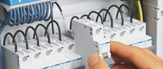
- Circuit breaker. This device is used to protect wiring from overcurrents.
- Overcurrent relay. This device is used for the same purpose as a fusible link fuse. This device reacts to an increase in current in the protected electrical circuit; with its help, you can create maximum protection against overload and short circuit currents.
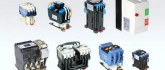
- Contactor. This device is used to remotely turn off or turn on electrical circuits whose power does not exceed 1000 Volts.
- Actuator. This device is used to safely remotely (using a button) turn on or turn off the power supply to installations. It is used in alternating current networks. The main working unit of the starter is an electromagnet. In addition to the main contact group, the device includes an auxiliary one.
- Delay relay. This device is used to create a time delay when other elements (devices) of the circuit are triggered. There are digital, semiconductor and electromagnetic delay relays.
- Thermal relay. This device is used to protect electrical equipment from overheating in the event of minor overloads of the asynchronous motor.
- Thyristor voltage regulator. This device is used to control the load current by controlling the firing angle of the thyristors.
- Magnetic amplifier. This device is used to increase load power with low control powers.
Are you an expert in this subject area? We invite you to become the author of the Directory Working Conditions
Definition 2
A thyristor is a semiconductor device that is made on the basis of a single crystal conductor with three or more p-n junctions, and also has two stable states: closed (low conductivity) and open (high conductivity).
ELECTRICAL RELAYS
This is a type of switching device whose function is to turn on or off an electrical circuit, under the influence of a control signal, or the occurrence of certain conditions. They are used everywhere - from household home networks to aircraft manufacturing, energy supply, and in all areas of electrical engineering.
In most cases, they have a combination of outputs with normally closed, open, and switching contacts, but can also be performed with one type of switching.
The industry produces relays that respond to various physical quantities - current, voltage, power, frequency, phase shift, temperature, radiation, sound vibrations, time, position in space.
By type they are divided into:
- primary - control outputs are connected directly to the “working” network;
- secondary - the signal for switching comes from any measuring element or transformer;
- intermediate - being part of the system, amplifying the control signal.
According to the internal structure and principle of operation, relays can be classified as electromagnetic, magnetoelectric, induction, semiconductor, ferroelectric, piezo, photo, thermal.
Electromagnetic
The devices are an inductor with a moving armature. Under the influence of a magnetic field, the latter switches the relay contacts. With the removal of the control signal, the core returns to its original position by springs. The cheapest and most common type.
Magnetoelectric
relay - a system of a movable frame with a winding connected to the outputs of a “signal” circuit, rotating in the field of a permanent magnet and acting on the contacts. They have high sensitivity, but the response speed does not exceed a tenth of a second.
Induction
— structurally consist of two fixed variable magnets and an armature. The control signal passing through the windings induces voltage in the moving element. The resulting electromotive force turns the armature, performing commutation. To generate EMF, it is necessary to differ in the phases of the current supplied to the control outputs, which allows the device to be used as a phase relay.
Thermal
- elements based on the property of solids to change volume depending on temperature. A bimetallic plate (usually brass and steel) bends when heated, switching the circuit. It is used in automatic circuit breakers for protection against overload and short circuit currents.
Semiconductor
— contactless devices, solid-state relays made on thyristors, IGBT transistors. They can be manufactured for switching significant powers, for currents of hundreds of amperes, regardless of the size of the control signal. High performance (microseconds) and reliability due to the absence of moving parts. The disadvantage is the high cost.
Ferroelectric
relays are switching devices based on the property of certain materials to change the direction of polarization under the influence of an electric field. Moreover, the dependence is nonlinear.
A similar principle is used by piezo and photo elements that stepwise increase and decrease resistance based on the amount of mechanical deformation or the power of light radiation. They are used in microelectronics, signaling, measurement, and information storage devices.
The choice of one or another type of relay depends on the required parameters:
- purpose, operating diagram, number of switched contacts, model;
- type, magnitude of current, voltage of the switched circuit, control signal;
- speed, number of operations, accuracy;
- operating temperature, fire and explosion safety class.
Selection of control and protection equipment for electrical equipment of power supply facilities
The choice of protection and control equipment for electrical equipment of power supply facilities is carried out based on:
- Power supply parameters.
- Requirements for the protection of power supply facilities.
The design of electrical devices is calculated and marked at the manufacturer individually for each type of device (current value, voltage, and mode). Thus, one of the ways to select equipment comes down to searching for the desired device in the manufacturer’s catalog.
When choosing control and protection devices, it is necessary to take into account the possibility of abnormal operating modes: phase-to-frame short circuits, phase-to-phase short circuits, voltage drop or disappearance, electric current increase, etc.
Why were these classes introduced?
The fact is that there is such a thing as the starting load current, which for some consumers can exceed the rated operating current several times. For example, any electric motors at the moment of starting (while the motor rotor is stationary) operate practically in short circuit mode, that is, they load the network only with the active resistance of the copper windings, which is small. And only when the motor rotor picks up speed, reactance appears, reducing the current. The starting currents of electric motors are 4-5 times higher than the rated (operating currents). (True, the duration of the inrush current flow is short; the bimetallic plate of the circuit breaker will not have time to operate).
If we use class B circuit breakers to protect engines, we will get a false triggering of the circuit breaker for starting current every time the engine starts. And we may not be able to start the engine at all. That is why class D circuit breakers must be used to protect engines.
protection of the machine from starting currents - electric motor
Class B - for the protection of lighting networks, heating devices, where inrush currents are minimal or completely absent. Accordingly, class C is for devices with medium inrush currents.
average starting currents - lighting lamps
Naturally, to select a circuit breaker, you need to take into account the voltage, type of current, operating environment, etc., but all this does not require special comments.
Repair of high-speed devices
Repair of any type of high-speed protective device must be performed in the same sequence. The high-speed switch, or BV, is purged with clean compressed air under a pressure of no more than 300 kPa (3 kgf/cm 2 ). After this, the device is wiped with napkins. Next, it is necessary to remove such elements as the arc chute, blocking device, pneumatic drive, armature with moving contact, inductive shunt and others.
Direct repair of the device is carried out at a special repair stand. The arc chamber is disassembled, its walls are cleaned in a special shot blasting unit, after which they are wiped and inspected. Chips may be allowed in the upper part of this chamber if their dimensions do not exceed 50x50 mm. The thickness of the walls at the break points should be from 4 to 8 mm. It is necessary to measure the resistance between the horns of the arc chute. For some samples, the indicator should be at least 5 MOhm, and for some, at least 10 MOhm.
The damaged partition must be cut down along its entire length. All similar areas of log houses must be thoroughly cleaned. After this, the surfaces to be glued are lubricated with an adhesive solution based on epoxy resin. If broken fan sheets are found, they are replaced. If they are bent, they must be straightened and returned to service. There is also an arc extinguishing coil, which must be cleaned of carbon deposits and melts, if any.
Source
Connection of circuit breakers
In the panel, single-pole circuit breakers are connected along the upper pole. The input phase power supply wire from the input circuit breaker is connected to this pole. There are three ways to connect the poles of circuit breakers
1.Using special flexible factory jumpers;
2.Using jumpers made by yourself;
3.Using special mounting rails.
For more details on connecting the poles of circuit breakers, read a separate article.
Types of circuit breaker releases
All releases used in circuit breakers can be divided into two groups. The first group includes devices that protect electrical circuits and are capable of recognizing the onset of a critical situation when overcurrents appear. As a result of activation, further development of the accident is stopped due to the divergence of the main working contacts.
The second group of releases is represented by additional devices that are not included in the basic package of the machines. On request the following can be installed:
- Independent releases capable of remotely turning off circuit breakers when a signal is received from the auxiliary circuit.
- Undervoltage release. Shuts down the machine if the voltage drops below permissible limits.
- Zero voltage release. Its contacts open when a significant voltage drop occurs.
Thermal release
The sample thermal release shown in the figure is made in the form of a bimetallic plate. During the heating process, it bends, changes shape and affects the release mechanism. To produce a plate, two metal strips are mechanically connected to each other. The material of each tape has a different coefficient of thermal expansion. The connection is made by soldering, welding or riveting. The bending of the plate is formed due to different changes in length during heating. Thermal releases provide protection against overload currents and can be configured for a specified operation mode.
Operating and heating modes of electrical devices
Any devices, regardless of the scope of application and the nature of the functions they perform, are designed for certain operating modes. Electrical devices can operate in short-term, intermittent, long-term and intermittently long-term modes.
There are two types of heating modes for electrical devices: steady-state and transient. The heating process can be considered established if, after one hour of heating, the temperature of the electrical apparatus increases by no more than 1 0 C.
In order to calculate the temperature value in the transition mode, it is necessary to use the heat balance equation.
Installation of circuit breakers
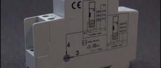
Circuit breakers are installed in distribution panels (electrical panels). Special devices are available for their fastening. They are called DIN rails or mounting rails .
A DIN rail is a curved metal plate with specially made perforations for attachment to a panel. The circuit breakers snap onto them (see photo).
To latch the circuit breaker onto the DIN rail, the latch is pulled out on the machine using a screwdriver, the circuit breaker is installed on the DIN rail, and the latch is released.
Causes of emergencies
The main causes of electrical
networks are:
- current leakage due to damaged or worn insulation, damp contacts;
- short circuit due to incorrect connection of electrical appliances;
- the occurrence of currents exceeding the characteristics of the wires due to the connection of devices of unacceptably high power;
- short circuit due to damaged insulation of electrical cables;
- short-term voltage surges (pulses), occurring, as a rule, due to lightning discharges;
- voltage fluctuations due to accidents in the external electrical network supplying energy to the electrical installation.
Depending on the cause of the malfunction, different electrical network protection devices are used to prevent consequences. Sometimes, for more reliable protection, they are combined or installed together with one another.
Testing of electrical machines, apparatus and instruments
To confirm full compliance with the stated requirements and standards, electrical machines are subjected to various types of tests, which are carried out at different stages of production and operation of the equipment.
Tests can be:
- acceptance - prototypes are subjected to such tests in order to subsequently launch the equipment into series;
- acceptance tests – carried out with each piece of equipment in order to establish optimal technical and operational parameters;
- periodic - carried out at a certain time and are designed to determine the compliance of the technical characteristics of the equipment with the stated requirements and standards of the enterprise;
- standard – necessary when making certain changes to the design of the device;
- certification – aimed at establishing quality standards for manufactured products;
- operational – carried out during the operation of the equipment. Such tests are aimed at identifying possible malfunctions and malfunctions in the operation of devices.
Electrical circuits for dummies: definitions, elements, designations
This article is for those who are just starting to study the theory of electrical circuits. As always, we will not get into the jungle of formulas, but we will try to explain the basic concepts and essence of things that are important for understanding. So, welcome to the world of electrical circuits!
Do you want more useful information and the latest news every day? Join us on telegram.
Connecting circuit breakers in the electrical network
At the end of the article, I will give two electrical circuits for connecting single-pole and three-pole circuit breakers. (For examples and explanations of the electrical circuits of the panel, read a separate article on the site: Electrical circuit of the panel.
©Elesant.ru
Normative references
GOST R 50345-99. Circuit breakers for overcurrent protection for household and similar purposes
Other articles in the section: Electrical networks
- Automatic circuit breakers
- Types of power transmission line supports by material
- Types of supports by purpose
- Overhead power lines with SIP wires
- Wooden supports for overhead power lines
- Reinforced concrete power transmission line supports
- Reinforced concrete power transmission line supports
- Protection of humans from electric shock, direct and indirect contact
- How does a 380 Volt low voltage consumer receive electricity?
- Cable network wells installation stages