Modern power supply systems are built on the basis of standard diagrams that take into account methods of grounding the equipment connected to them. This is done in order to protect the end consumer, as well as personnel working at electrical installations. When organizing modern networks, cables are traditionally used that include not only a phase core, but also a working neutral N, as well as a protective PE conductor. In some cases, these two types of buses are combined into one common PEN core. To understand their functional purpose, you will first have to find out what a PE bus is and how the color marking of the remaining conductors is carried out.
Types of grounding systems
Known electrical equipment protection systems differ in a number of ways, according to which they are divided into the following types: TN-S, TN-C, TN-CS, TT, and IT. The icons included in these designations are deciphered as follows:
- T stands for ground (from the French "Terre" or earth).
- N is the connection to the transformer neutral.
- I means isolated.
- C – combining the functions of the working and protective neutral conductors (“common”).
- S – separate use of these cores (“select”).
According to the PUE, TN-C means a system grounded to neutral with combined protective and working conductors.
The designation TN-CS means that in some part of the power circuit two conductors are laid together, and then they are separated according to functionality.
Reliable grounding of the PE conductor to the ASU
To install a grounding loop, you need three rolled steel pins with a diameter of at least 16 mm and a length of 3 m. They are driven into the corners of an equilateral triangle into a pre-dug trench 30-50 cm deep. The sides of the triangle should be 2.5 - 3 m. The upper ends of the pins are welded between a steel strip measuring 4x30 mm.
Ground loop
Tip #1. The distance from the ground loop to the building wall should be from 1 to 6 m.
Instead of rolled steel, it is allowed to use a pipe with a diameter of at least an inch and a quarter with a wall thickness of 3.5 mm or a steel angle of 50x50 mm. To make driving easier, the ends of the pins need to be sharpened with a handy tool. The welding points and the connecting bus must be well painted to protect against corrosion. Important! Grounding pins must not be painted!
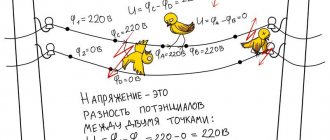
A steel or copper conductor is laid from the circuit to the PE bus. The cross-section of the steel conductor must be at least 100 mm2, and the copper conductor must correspond to the cross-section of the PE conductor or more. After installing the grounding loop by the energy supply organization, it is necessary to measure the spreading resistance of the grounding loop. It should be no more than 10 Ohms when powered by three-phase current with a linear voltage of 380 V (phase voltage - (220 V).
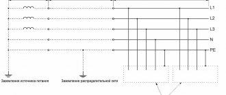
Classification of zero buses
According to the functions performed, the zero buses included in the power supply system are divided into the following types:
- N – functional or working “zero”, which is a conductor for load currents.
- PE is a specially laid protective “zero” that provides the ability to organize grounding at the receiving end in a convenient place.
- PEN is a conductor that combines the functions of both of these buses.
N
P.E.
PEN
Each of the conductors in the diagrams is highlighted in a certain color (N - blue, PE - yellow-green, and PEN - a combination of these). They must be selected according to their cross-section, which should not be less than the same indicator for phase buses.
This decoding also makes it possible to understand why it is necessary to separate the PEN conductor, what it serves, and how grounding can be arranged on the consumer side.
TECAFINE PE-HD
- standard nomenclature and always in stock in various colors and sizes. Due to low, almost zero, water absorption and excellent weldability, polyethylene sheets are used for cladding/lining baths, containers, swimming pools and are supplied in sheets with a thickness of 1mm to 200mm and sizes from 1000x2000mm to 6200x2010mm. Polyethylene rod (round) is used for the manufacture of bushings, plain bearings, round seals, spacer rings, inserts and other round or spherical parts. Polyethylene rods are supplied in various colors with diameters from 8mm to 800mm and lengths up to 2000mm.
Why divide PEN into two parts?
Correct division
Dividing the PEN wire into PE and N cores only makes sense when each of them is intended to be used for its intended purpose. This can be done in the following cases:
- in a private (country) house, when a tap from the PE bus is made in the distribution board, used to organize local re-grounding;
- in a city apartment building, where the residents of the entrance agreed to install a common grounding loop on the street next to the entrance;
- a copper descent is carried out from the PE wire to a homemade ground loop.
To implement grounding with a homemade circuit, permission from the relevant energy services and approval from the housing and communal services will be required.
When in city houses a jumper is placed between the buses in the driveway panel, there is no need to talk about full grounding. The regulatory documentation on this matter provides a recommendation without a detailed explanation of the effect of such “grounding”.
Organization of the TN-CS system in accordance with the Electrical Installation Rules (PUE)
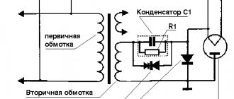
Clause 1.7.135 of the PUE specifies exactly how to properly divide the PEN conductor into separate and independent PE and N. For this, at the point of separation (splitting) of the PEN conductor, separate busbars or terminal blocks are provided for connecting PE and N conductors. The separated buses are connected to each other by a jumper. The input PEN conductor of the power supply line is connected to the PE conductor bus.
Important! Reconnection of PE and N conductors beyond the separation point is not allowed. The electrical installation rules (clauses 1, 7, 145) prohibit the installation of any switching devices and devices in PE and PEN conductor circuits. The insulation of PEN, PE and N conductors must be the same as that of phase conductors, and their cross-section must be determined according to the table:
| Cross-sectional area of phase conductors | Smallest cross-sectional area of protective conductors |
| S ≤ 16 mm2 | S |
| 16 mm2 < S ≤ 35 mm2 | 16 mm2 |
| S ≥ 35 mm2 | S/2 |
Conductor splitting options
Input distribution device
In the distribution board, where the PEN conductor is separated, grounding is organized using the splitting method, but a jumper must be installed between N and PE. It is important that the earth bus is connected first, and only after that the connection of the working core is completed. In this situation, there are four possible options for connecting the PE wire:
- There is no jumper between it and conductor N - the working zero contact and the grounding bus are not electrically connected. An RCD is also not installed in the protective circuit.
- There is a jumper between these terminals, but the RCD is not installed.
- PE for grounding and N are short-circuited and an RCD is installed.
- There is no jumper, but there is an RCD.
In the first case, the “physics” of the activation of protective circuits looks like this:
- The emergency phase hits the device body.
- Then it goes to the ground bus.
- Further along it goes to the circuit of the transformer substation.
When considering the problem, it is important to take into account the resistance of the grounding circuit, which usually does not exceed 20 Ohms, taking into account the cross-section of the PE conductor in mm. square. In the event of an accident, the short-circuit current will not be enough to turn off the input circuit breaker. The protective circuit will function until the damaged area on the receiving side burns out completely. This situation will not cause any significant harm to a person, but the equipment will suffer serious damage (the worst case scenario is that it catches fire and ignites).
There is a jumper, but there is no RCD
Separation diagram of a PEN conductor for a single-phase network.
In this case, the length of the supply line (removal of the location of its damage from the input distribution panel), which determines the resistance of the wire for charge flow, plays an important role. In the event of an emergency phase short circuit to the frame of damaged equipment, the leakage current first flows to the grounding bus. Then it has only two ways: part of the emergency electricity goes into the ground, and the other along the zero bus will trigger the machine at the input. In the situation considered, the jumper is used in case the AV does not work for some reason. But since the latter is practically impossible, it makes no difference whether it is present or absent.
There is a jumper and an RCD is installed
Since all protective and working conductors have a certain resistance, in this case the RCD should operate normally. When a short circuit occurs on the housing, the leakage current first flows to the RCD itself and only then goes to the input of the residential building. Here, as in the previous case, it is divided into two parts: some part of the whole goes into the ground, and part returns through the jumper to the panel, turning off the input machine. However, as a rule, things don’t come to this, since the RCD is triggered much faster.
In this situation, the jumper does not have much significance and is only a safety net, just in case: if suddenly, by a strange coincidence, the RCD does not work.
There is no jumper and an RCD is installed
This circuit will work in the same way as if there was a jumper. The only difference from the previous case is the lack of insurance if the RCD fails, which is unlikely. If this does happen, the circuit will begin to work according to the first of the considered options. In this case, the input device does not operate until the short circuit to the housing is transformed into a phase short circuit.
Typical phase splitting errors are associated with violations of the commutation order. You cannot connect the working conductor first and only after it connect the grounding. Another typical mistake is the reluctance to install an RCD. In circuits with artificial splitting of the PEN conductor, the presence of a residual current device is mandatory.
Grounding symbol (PE)
In addition to the designation of phase and zero, electricians also use a special letter indication PE (Protective Earthing) for the ground wire. As a rule, they are always included in the cable, along with the neutral and phase conductors. Contacts and clamps intended for switching with the grounding neutral wire are also marked in a similar way.
For ease of installation, the grounding conductors are placed in yellow-green insulation. The DIYer should understand that these colors always indicate the ground wires only. Yellow and green are never used to indicate phase and zero in electrical engineering.
As practice shows, when organizing electrical networks in residential buildings, violations of generally accepted standards for the use of insulation color and corresponding alphanumeric markings are sometimes allowed. In this case, it is not always enough to have the ability to decipher the designations L, N or PE.
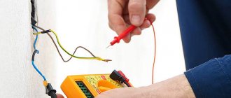
In order for the connection of electrical equipment to be truly safe, it is necessary to check whether the markings correspond to the actual state of things. To do this, use special devices (testers) or improvised devices. If you have no experience in such work, for your own safety it is better to invite an experienced electrician with the appropriate permit.
Designation l and n in electrics
The designation of phase and zero in electrics was introduced to ensure that electrical networks are safe and easy to use. For this purpose, special letter markings (l and n) and insulation of the corresponding color are used. There may also be conductors marked PE in yellow-green color: this is how grounding wires are designated.
In addition, the same letter designations are used on connecting contacts and terminals. All that needs to be done when installing an electrical appliance is to connect each of the wires to the terminal. To be on the safe side, it is advisable to check each of the wires with a tester.
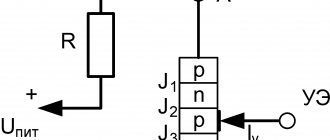
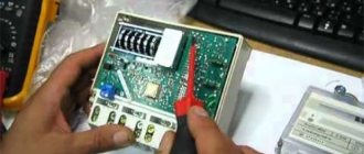
The photo below is a good example of how L and N are designated in electrical equipment. In particular, the photo shows the UZM (multifunctional protection device) terminals for correct connection of the wires.
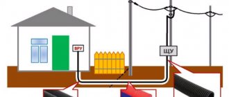
Features of PEN conductor separation
In private houses and city apartments, in order to prevent the theft of electricity, representatives of the controlling organization have the right to demand that the PEN wire be extended to the meter. And only after the metering device do they allow it to be divided into a protective bus PE and a working bus N. Such a connection does not contradict the requirements of the PUE, but the division made before the meter looks much more natural.
Scheme for single-phase power supply of single-family and rural residential buildings
If you first make a separation and then seal the input machine, there can be no objections from representatives of Energosbyt and inspectors.