Differential current protection is one of the types of relay protection, which is characterized by high efficiency and also has relatively good response speed. It is used both for power equipment (motors, transformers, generators and bus sections), and recently it has become widely used to protect household objects from phase faults. This became possible due to special compact devices similar in design to a regular circuit breaker.
However, some power equipment is simply required, according to power supply regulations, to be equipped with high-speed differential relay protection. Among the varieties of DFZ, there are two main types:
- longitudinal;
- transverse
In order to understand whether differential phase protection is needed for a particular electrical equipment and how to implement it, you need to understand the principle of its operation, as well as understand the installation nuances.
Operating principle of differential protection
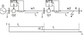
The action of this protection is based on comparing the currents that enter and exit the area in need of protection. For such a comparison of current values, current transformers are used, since only through them is it possible to measure large current values. This is best seen in the simplest diagram below.
In the diagram, the current transformers are designated TA1 and TA2. Their secondary circuits are connected to the KA current relay. Thus, it turns out that the winding of the main protection relay receives the difference in current values from the two transformers, and during normal operating processes it will be equal to zero, which means the KA relay will remain unplugged. However, if an interphase short circuit (short circuit) occurs in the circuit that is being protected, then the relay winding will receive a value equal to the sum of several currents, this will set in motion the moving part of the electromechanical relay, which, in turn, will close the contacts and will give a signal to disconnect the equipment from the source of electrical energy. However, this is all in theory, but in practice a certain small unbalance current will always flow through the relay coil, which must be taken into account when calculating the coil.
Here are several reasons for this negative phenomenon:
- CTs (current transformers) can have characteristics that differ significantly from each other. To reduce these indicators, more precise transformers are used, manufactured in pairs specifically for this type of protection;
- Due to the magnetizing current arising in the winding of the protected transformer at the moment it is turned on from the idle mode to the operating mode with a load present. In order to avoid false operation of the KA relay, it is necessary to select a relay operation current greater than the highest value of the magnetizing current that the protected object, in this case a transformer, can produce;
- Due to different connections of windings (star-delta and vice versa). To do this, you need to select the number of turns of current transformers involved in differential protection in such a way that they compensate for these unfavorable values.
The unbalance current in differential protection that occurs during operation is a negative phenomenon that must be combated and which must be taken into account when calculating this protective electrical equipment.
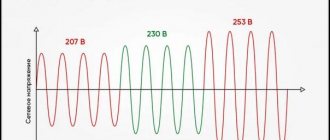
Differential protection in networks 0.23-0.4 kV
To increase the efficiency of power transmission lines, devices are used whose operating principle is based on magnetic-electric relays.
Principle of operation
Differential devices (differential circuit breakers and residual current devices) installed at inputs to residential and administrative buildings, when electric current passes through them, compare the values of the incoming and outgoing current. If the values do not match, the circuit is automatically disconnected.
Causes of leakage current:
- touch of living organisms to exposed conductors;
- breakdowns in the insulation of electrical wiring and cables of household electrical appliances.
If the automation operates without load, then such a device cannot be considered serviceable, or leakage currents are flowing in the switchboard itself. If you know that the device is working properly, you must turn off all the machines after the RCD. The principle of their sequential reconnection determines the emergency section of the electrical circuit.
When the RCD trip is triggered for the first time, it is necessary to start it again, because false alarms of the device are possible. If the shutdown repeats, there is a fault in the network.
The cut-off values of the differential protection are selected from the standard range depending on the purpose: fire safety, incoming differential circuit breakers, apartment and feeder RCDs, RCDs for wet rooms and children's rooms. RCDs at 10 and 30 mA protect a person from ventricular fibrillation.
It is implemented by installing differential circuit breakers and RCDs at inputs to cottages and group panels. It is generally accepted that the most effective security is three-level, when several devices operate: 100-300, 30 and 10 mA simultaneously.
Differential current protection can be effective in apartments with wiring without grounding. It is sensitive to leakage currents, therefore it provides complete safety from electric shock.
Residual current device
It is necessary to regularly check the functionality of residual current devices (at least once every 3 months). Why is there a “TEST” button on the device body?
Differential circuit breakers combine the functions of a switch and an RCD:
- protect lines from overload;
- disconnection of contacts in the presence of leakage currents.
Modern differential current protection can provide complete safety from electric shock.
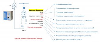
Tire differential protection (TIP)
Features of the application and operation of various transformer protections
Busbars and busbar assemblies are a key reliable current-carrying element of an electrical installation, connecting the voltage source to the switchgear or the operating unit itself. It is characterized by high load capacity and the ability to visually monitor the condition of insulators. At the same time, many people know that it is necessary to implement circuits that protect electrical equipment, but the busbars very often remain unprotected.
Main types of tire damage:
- Incorrect or erroneous manipulations by maintenance personnel with switching of bus disconnectors;
- Phase overlap or short circuit to ground due to deterioration of insulation through contamination of insulators;
- Breakdown during aggressive atmospheric phenomena (thunderstorm, lightning);
- Malfunctions of the disconnector insulators on both sides.
To protect busbars, differential current protection is mainly used. The principle of its operation is similar, and is based on comparing the currents in the connections of the protected buses. When the busbars are in normal operating condition, only unbalance current flows in the differential protection relay coil, which does not operate the relay moving mechanism. During a phase fault, the protection relay will receive a current whose value will be equal to the sum of all currents supplying the connection where the breakdown occurred.
The main advantages of such protection are:
- High response speed;
- Excellent selectivity;
- Relatively simple implementation.
There is only one drawback here - it is a false alarm, which is most often possible when the installation (connecting) wires break, which can occur due to various reasons, both electrical and mechanical. In order to minimize the probability of false triggering, it is necessary to select the operating current of the DPS a little more than the operating current of the most powerful connection. The coverage area of this protection is limited directly to the gap where the CTs are installed; its operation is aimed at disconnecting all supply connections from voltage. To manually monitor the unbalance current, a milliammeter is installed on the control panel and maintenance personnel are required to check it by pressing the corresponding button. Personnel are required to perform this action once per shift, recording it in the operational log.
The differential protection of the busbar is disabled in the following cases:
- The appearance of a sound or light signal about a malfunction of current circuits or an increase in unbalance current;
- If a new connection has occurred, the current circuits of which are not connected to the protection system, and were not correctly phased;
- During a routine check of this protection.
Types of relays
Among all the models existing on the market, the following can be distinguished:
Differential relay, the main area of application of which is industry and marine vessels. The design of this equipment includes several relays, which are required to ensure safety and efficiency at the site.
They went on sale more than 60 years ago, their operating pressure range is 0-11 bar. The design has a system of replaceable contacts, which can be gold-plated. They have fault tolerance and an adjustable differential. This equipment is IP66 rated and can be supplied with a dead zone upon request. If installation on a ship is intended, the equipment must be supplied with the necessary permits.
- Equipment that satisfies the most stringent requirements regarding low differential value and protection. The design differs from competitive models in strength, accuracy, vibration resistance and good resistance to mechanical damage. The equipment can be used indoors and outdoors, with a working pressure range of 0.2-2.5 bar and a protection class of IP67. There is a microswitch on the housing.
- Equipment that is used in places where compactness and reliability are required. The relay design was created in accordance with the new concept, so the equipment is classified as a block type unit. The relay can withstand harsh operating conditions, and the fixed differential value allows for high precision operation. The operating pressure range is 0.3-5 bar, and as an addition it is possible to adjust the differential.
- Compact model with operating pressure from 0.3 to 5 bar. The equipment copes with the task perfectly even in the conditions of the ship’s engine room, which indicates strength, reliability and vibration resistance. Such equipment is attractive due to its low installation costs, compact design and IP66 protection class. Write comments or additions to the article, maybe I missed something. Take a look at the site map, I will be glad if you find something else useful on my site.
Longitudinal differential generator protection
Features of installation of electrical equipment
To protect various generators from multiphase short circuits. longitudinal differential protection has received the most widespread use. It is connected in the same way as the previous one to the CT, only they are installed from the zero point of the generator, as well as from the terminals. Its coverage area is:
- windings of an electric machine;
- stator output;
- buses or cables that are laid to the switchgear.
The operation current of such protection is set according to the condition of setting the unbalance current passing through the differential protection relay during external short circuits. A protection circuit for a high-sensitivity generator is presented, using the most reliable RNT relays for this case.
The operation current of such a circuit is set according to two conditions:
- Setting the actual unbalance current;
- Setting the current that will flow when the installation wires break.
What does it look like and where is it located in the transformer?
A pressure switch is a relay in a transformer station with three rods, which are characterized by the presence of windings. The executive body is an output current pressure switch.
On the last rod of the transformer station there are terminals of the secondary winding, to which the thermostat is connected. On the middle rod there are 2-3 primary windings, which are connected to transformer currents. The device is characterized by the presence of additional short-circuited windings, with the help of which the aperiodic component is suppressed.
Note! To adjust the presosstat, the number of turns in the primary winding is switched, as a result of which equality of magnetic fluxes is achieved in the magnetic circuit. The operating currents of the output thermostat and the required braking during the transient process are set by changing the resistances of resistors in the compensating and output circuits
The operating currents of the output thermostat and the required braking during the transient process are set by changing the resistances of resistors in the compensating and output circuits.
Generator protection
RTN is used to ensure full operation of the relay protection and automation system of a power transformer station. When connected to the electrical network, powerful magnetizing currents immediately appear in their core. When they fade quickly, a precedent is created for engine protection. This is explained by the fact that the magnetizing power remains in the transformer station like a torus.
Detuning from magnetizing currents is ensured thanks to the RTH device. Rapid magnetization of the core of a transformer station is observed with a sharp surge of current, as a result of which the pressure switch does not respond to such a phenomenon. If the pressure switch is installed on a powerful through short circuit, then it can operate when exposed to unbalance currents.
Differential protection is designed for the full functioning of the electrical network. It provides regulation of currents and shutdown when they are violated. Do not neglect this device for the sake of safety.
Generator transverse differential protection
Features of the application and use of the RCD device
This protection is performed to protect against vik short circuits that can occur directly in the stator winding, and, of course, if there are parallel branches of the stator windings. This is possible by comparing the current values of these branches for each phase. Transverse differential protection is carried out in such a way that for each of the phases it is organized separately, that is, it will respond to interturn short circuits only in one of the phases.
The current at which the transverse differential protection coil is drawn in is adjusted according to the maximum unbalance current that can flow in the relay during various external short circuits, and is taken equal to:
When setting up a differential protection system, it is recommended to make a more accurate calculation of the setting, taking into account absolutely all actual unbalance currents flowing, and not calculated ones. As experience shows during operation, on turbogenerators they are relatively small, and their operating current does not require additional adjustments and adjustments. On hydrogenerators, on the contrary, the magnitudes of these unwanted currents are large, therefore it is necessary to significantly coarse the settings of the relay of this transverse protection, which sometimes reduces its super-efficiency.
As a result, I would like to note that the calculation and configuration of these protections should only be carried out by professionals who have experience in this field, most often these are engineers from electrical design bureaus. Differential phase protection in everyday life is also very effective and even a novice electrician can perform it on the basis of compact devices sold in specialized stores; there should not be any connection difficulties. The main thing is to follow basic electrical safety rules.
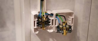
AB+RCD
The traditional method of protection is to install a circuit breaker and an RCD.
VA47-29 and VD1-63 (UZO) IEK
VA47-29: ultimate breaking capacity - 4500 A, rated current - from 0.5 to 63 A
Differential switch: type A or AC, rated current from 16 to 63 A, rated differential disconnecting current - 10, 30, 100 mA.
If we install these two devices together, then the circuit breaker (AB) operates in the event of an overload or short circuit (thermal and electromagnetic release), and the RCD – in the event of a leak.
This option allows you to configure switches and RCDs to suit your needs. For example, a widely used scheme is in which one RCD “serves” several lines, each of which is connected through its own circuit breaker. This is especially true in budget billboards.
On the other hand, an inexperienced electrician may make a mistake by choosing the wrong rating or mixing up the wires.
Automatic residual current switches combine the functions of AV and RCD. In most cases, it is enough to select the desired rated current and rated residual current - and protection is provided. IEK has several lines of RCBOs.
Different TT coefficients in DZT
To equalize the secondary currents on different sides of the power transformer, it is necessary that the rated primary currents of the power transformer be equal to the rated primary currents of the CT, and when connecting the CT in a “delta”, the rated primary current of the CT is √3 times less than the rated current of this side of the power transformer.
CTs have a standard scale of nominal values, therefore, to equalize secondary currents on different sides of the transformer, intermediate autotransformers (transformers) or magnetic equalization are used by connecting secondary current circuits to different numbers of turns.
However, all these methods do not allow the secondary currents to be accurately balanced (impossibility of setting a fractional number of turns or due to the discreteness of the taps of the winding turns, etc.), so an additional component of the unbalance current appears . This component is determined:
| (1 – 8 ) |
where Wcalc is the calculated number of turns; Wust – the set number of turns. The estimated number of turns is determined by the expression:
| (1 – 9) |
where Wosn and Inom. main – number of turns and rated current of the side of the protected transformer, taken in the calculation as the main one; Wcalc and Inom – the calculated number of turns and rated current of the side of the protected transformer, taken in the calculation as the non-main one.
It should be noted that in modern digital relays it is possible to minimize this component of the unbalance current (to a level of ≈ 1%).
Related links
- Berkovich M.A. Molchanov V.V. Semenov V.A. Fundamentals of relay protection technology / Regulatory document dated November 29, 2022 at 11:56
- Nagai V.I. Relay protection of branch substations of electrical networks / Regulatory document dated February 25, 2022 at 14:04
- Maintenance of current and voltage measuring transformers. Ed. Alekseeva B.A. / Regulatory document dated January 30, 2022 at 11:22
- RD EO 1.1.2.03.0537-2006 / Regulatory document dated September 12, 2011 at 13:04
- Relay protection of energy systems. / Regulatory document dated April 8, 2008 at 09:53
- Kireeva E.A. Tsyruk S.A. Relay protection and automation of electric power systems / Regulatory document dated December 25, 2019 at 17:17
- Shabad M.A. Current transformers in relay protection circuits. Part two. Calculations for protection circuits on alternating operating current / Regulatory document dated January 14, 2022 at 12:36
Rate this article: