In this article, I decided to put together a complete step-by-step guide for Arduino beginners. We will look at what Arduino is, what you need to start learning, where to download and how to install and configure the programming environment, how it works and how to use the programming language, and much more that is necessary to create full-fledged complex devices based on the family of these microcontrollers.
Here I will try to give a condensed minimum so that you understand the principles of working with Arduino. For a more complete immersion in the world of programmable microcontrollers, pay attention to other sections and articles of this site. I will leave links to other materials on this site for a more detailed study of some aspects.
What is Arduino and what is it for?
Arduino is an electronic construction kit that allows anyone to create a variety of electro-mechanical devices. Arduino consists of software and hardware. The software part includes a development environment (a program for writing and debugging firmware), many ready-made and convenient libraries, and a simplified programming language. The hardware includes a large line of microcontrollers and ready-made modules for them. Thanks to this, working with Arduino is very easy!
With the help of Arduino you can learn programming, electrical engineering and mechanics. But this is not just an educational constructor. Based on it, you can make really useful devices. Starting from simple flashing lights, weather stations, automation systems and ending with smart home systems, CNC machines and unmanned aerial vehicles. The possibilities are not even limited by your imagination, because there are a huge number of instructions and ideas for implementation.
Arduino projects
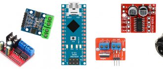
Arduino Starter Kit
In order to start learning Arduino, you need to acquire the microcontroller board itself and additional parts. It is best to purchase an Arduino starter kit, but you can choose everything you need yourself. I recommend choosing a set because it's easier and often cheaper. Here are links to the best sets and individual parts that you will definitely need to study:
| Basic Arduino kit for beginners: | Buy |
| Large set for training and first projects: | Buy |
| Set of additional sensors and modules: | Buy |
| Arduino Uno is the most basic and convenient model from the line: | Buy |
| Solderless breadboard for easy learning and prototyping: | Buy |
| Set of wires with convenient connectors: | Buy |
| LED set: | Buy |
| Resistor kit: | Buy |
| Buttons: | Buy |
| Potentiometers: | Buy |
Arduino IDE development environment
To write, debug and download firmware, you need to download and install the Arduino IDE. This is a very simple and convenient program. On my website I have already described the process of downloading, installing and configuring the development environment. Therefore, here I will simply leave links to the latest version of the program and to an article with detailed instructions.
| Version | Windows | Mac OS X | Linux |
| 1.8.2 | Zip Installer | Installer | 32 bits 64 bits ARM |
Arduino programming language
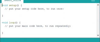
When you have a microcontroller board in your hands and a development environment installed on your computer, you can start writing your first sketches (firmware). To do this, you need to become familiar with the programming language.
Arduino programming uses a simplified version of the C++ language with predefined functions. As in other C-like programming languages, there are a number of rules for writing code. Here are the most basic ones:
- Each instruction must be followed by a semicolon (;)
- Before declaring a function, you must specify the data type returned by the function, or void if the function does not return a value.
- It is also necessary to indicate the data type before declaring a variable.
- Comments are designated: // Inline and /* block */
You can learn more about data types, functions, variables, operators and language constructs on the Arduino programming page. You don't need to memorize and remember all this information. You can always go to the reference book and look at the syntax of a particular function.
All Arduino firmware must contain at least 2 functions. These are setup() and loop().
setup function
The setup() function is executed at the very beginning and only 1 time immediately after turning on or rebooting your device. Typically, this function declares pin modes, opens the necessary communication protocols, establishes connections with additional modules, and configures connected libraries. If your firmware does not need to do anything like this, then the function should still be declared. Here is a standard example of the setup() function:
void setup() { Serial.begin(9600); // Open a serial connection pinMode(9, INPUT); // Assign pin 9 to the input pinMode(13, OUTPUT); // Assign pin 13 as output }
In this example, a serial port is simply opened for communication with the computer and pins 9 and 13 are assigned as input and output. Nothing complicated. But if you don’t understand anything, you can always comment below.
loop function
The loop() function is executed after the setup() function. Loop translated from English means “loop”. This indicates that the function is looped, that is, it will be executed over and over again. For example, the ATmega328 microcontroller, which is found in most Arduino boards, will execute the loop function about 10,000 times per second (if delays and complex calculations are not used). Thanks to this, we have great opportunities.
Prototyping/layout
To assemble the breadboard, we need the following elements: LED, resistor, wiring (jumpers), breadboard. In order not to burn anything, and in order for everything to work successfully, you need to deal with the LED. It has two "legs". Short is a minus, long is a plus. We will connect the ground (GND) and a resistor to the short one (in order to reduce the current supplied to the LED so as not to burn it), and we will supply power to the long one (connect to pin 13). After connecting, upload the sketch to the board if you have not done so previously. The code remains the same.
This is the end of the first part. Thank you for your attention.
Breadbord development board
You can create simple and complex devices. For convenience, I recommend purchasing a breadboard and connecting wires. With their help, you don't have to solder and resolder wires, modules, buttons and sensors for different projects and debugging. With a solderless breadboard, development becomes easier, more convenient and faster. I told you how to work with a breadboard in this lesson. Here is a list of solderless breadboards:
| 800 point development board with 2 power rails, power supply board and wires: | Buy |
| Large 1600 point development board with 4 power rails: | Buy |
| Development board for 800 points with 2 power rails: | Buy |
| Development board for 400 points with 2 power rails: | Buy |
| 170 point development board: | Buy |
| Connecting wires 120 pieces: | Buy |
First project on Arduino
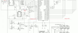
Let's build our first Arduino-based device. We will simply connect the clock button and LED to the Arduino. The project diagram looks like this:
LED brightness control
Note the additional resistors in the circuit. One of them limits the current for the LED, and the second pulls the button contact to ground. I explained how it works and why it is needed in this lesson.
In order for everything to work, we need to write a sketch. Let's make the LED light up after pressing the button, and go out after the next press. Here's our first sketch:
// variables with pins of connected devices int switchPin = 8; int ledPin = 11; // variables to store the state of the button and LED boolean lastButton = LOW; boolean currentButton = LOW; boolean ledOn = false; void setup() { pinMode(switchPin, INPUT); pinMode(ledPin, OUTPUT); } // function for debouncing boolean debounse(boolean last) { boolean current = digitalRead(switchPin); if(last != current) { delay(5); current = digitalRead(switchPin); } return current; } void loop() { currentButton = debounse(lastButton); if(lastButton == LOW && currentButton == HIGH) { ledOn = !ledOn; } lastButton = currentButton; digitalWrite(ledPin, ledOn); }
In this sketch, I created an additional debounse function to suppress contact bounce. There is a whole lesson on contact bounce on my website. Be sure to check out this material.
Connection diagram
Shown in the following figure.
We will connect the button to the second pin of the Arduino, that is, one end of the button will be connected to the second pin of the Arduino, and the other to the ground. That is, whenever we press a button, ground will be supplied to the second pin of the Arduino.
The LED is connected to pin 3 through a 1 kOhm resistor. That is, the cathode of the LED is connected to ground, and the anode is connected to pin 3 of the Arduino through a resistor.
PWM Arduino
Pulse width modulation (PWM) is the process of controlling voltage using the duty cycle of a signal. That is, using PWM we can smoothly control the load. For example, you can smoothly change the brightness of an LED, but this change in brightness is obtained not by decreasing the voltage, but by increasing the intervals of the low signal. The operating principle of PWM is shown in this diagram:
PWM Arduino
When we apply PWM to the LED, it starts to quickly light up and go out. The human eye is not able to see this because the frequency is too high. But when shooting video, you will most likely see moments when the LED is not lit. This will happen provided that the camera frame rate is not a multiple of the PWM frequency.
Arduino has a built-in pulse width modulator. You can use PWM only on those pins that are supported by the microcontroller. For example, Arduino Uno and Nano have 6 PWM pins: these are pins D3, D5, D6, D9, D10 and D11. The pins may differ on other boards. You can find a description of the board you are interested in in this section.
To use PWM, Arduino has the analogWrite() function. It takes as arguments a pin number and a PWM value from 0 to 255. 0 is 0% high fill, and 255 is 100%. Let's write a simple sketch as an example. Let's make the LED light up smoothly, wait one second and fade out just as smoothly, and so on ad infinitum. Here is an example of using this function:
// The LED is connected to pin 11 int ledPin = 11; void setup() { pinMode(ledPin, OUTPUT); } void loop() { for (int i = 0; i < 255; i++) { analogWrite(ledPin, i); delay(5); } delay(1000); for (int i = 255; i > 0; i—) { analogWrite(ledPin, i); delay(5); } }
Loading LED Flashing Program
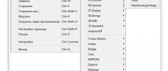
Now let's load our first program into the Arduino board using the Arduino IDE, which we just recently installed. The installed Arduino IDE contains several example programs that will be very useful for beginners. Let's open one of these example programs using the following path File -> Examples -> Basics -> Blink (as shown in the picture).
This will open the Blink program - its purpose is to make the built-in LED on the Arduino board blink. After opening the program, we need to select the correct Arduino board - to do this, select the menu item Tool -> Boards -> Arduino UNO/Genuino as shown in the figure below.
Next we must select the correct port for our board. Earlier we saw that our board had a COM13 port defined. In your case it may be a different port. But for our case under consideration, we must select the menu item Tools -> Port -> COM13.
If everything is done correctly, you should notice that the port number (in our case COM 13) will appear at the bottom of the screen. After this, you need to click the download button (highlighted in blue) to the Arduino board as shown in the figure below.
After clicking this button, you will see the message “Compiling sketch” and then if the program upload is successful, you will see the message “Done Uploading” as shown in the image below.
If at this stage you encounter any errors that are not discussed in this article, then you can try to find them in the article about the 10 most common errors when working with Arduino.
Now let's try to write a program that will light up an LED when a button is pressed.
Arduino analog inputs
As we already know, digital pins can be both input and output and receive/give only 2 values: HIGH and LOW. Analog pins can only receive a signal. And unlike digital inputs, analog inputs measure the voltage of the incoming signal. Most Arduino boards have a 10-bit analog-to-digital converter. This means that 0 is read as 0 and 5 V is read as 1023. That is, analog inputs measure the voltage applied to them with an accuracy of 0.005 volts. Thanks to this, we can connect a variety of sensors and resistors (thermoresistors, photoresistors) and read the analog signal from them.
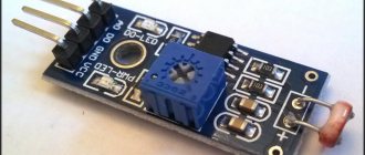
For these purposes, Arduino has the analogRead() function. For example, let's connect a photoresistor to the Arduino and write a simple sketch in which we will read the readings and send them to the port monitor. This is what our device looks like:
Connecting a photoresistor to Arduino
The circuit contains a 10 kOhm pull-down resistor. It is needed to avoid interference and interference. Now let's look at the sketch:
int sensePin = 0; // The pin to which the photoresistor is connected void setup() { analogReferense(DEFAULT); // Set the reference voltage value. This line is optional. Serial.begin(9600); // Open the port at 9600 baud. } void loop() { Serial.println(analogRead(sensePin)); // Read the value and output it to the port delay(500); // delay so that there are not too many values }
This is how we made a light sensor from two simple elements and four lines of code. Based on this device, we can make a smart lamp or night light. A very simple and useful device.
So we looked at the basics of working with Arduino. Now you can make simple projects. To continue learning and master all the intricacies, I advise you to read books on Arduino and take a free training course. After this, you will be able to do the most complex projects you can think of.
Specifications
Well, more specifically, the technical characteristics of this controller are as follows:
- The core clock speed reaches 16 MHz.
- The perceived voltage is 5 Volts.
- The maximum permissible voltage on the circuit is 20 V.
- Accordingly, the average recommended for operation is 9 V +-2 V
- From one output, the maximum current can reach 40 mA.
- Well, the main thing is that there are 54 digital pins, 15 of which support PWM.
- There are only 16 analogue ones, but for most projects this will be enough.
- Available persistent memory is 256 KB, but be aware that the compiler is using 8.
- The operational memory is only 8 KB.
All these characteristics must be remembered in order to select projects that match the parameters for the Arduino mega 2560. After all, not in every situation there will be room to fit such a long chip, and indeed there will be a need for it.