The continuous permissible current of a cable is an important performance characteristic that must be taken into account when calculating the conductor cross-section. If an incorrect value is obtained, then during the use of the electrical network the wire will constantly overheat.
A short-term increase in temperature as a result of a short circuit is possible, but an incorrect cross-section threatens to increase the long-term permissible temperature. This will subsequently lead to damage to the insulation and fire.
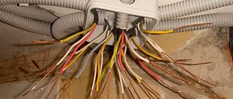
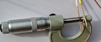
When installing electrical wiring, you need to determine the required cable cross-section
Basic Concepts
Any metal product consists of a crystal lattice. Electrons and mobile particles pass through it, which is why electricity is transformed into thermal energy. This property is successfully used by manufacturers of heaters and lighting devices. However, in conventional electrical systems, overheating of the cable is unacceptable, since over time it will lead to insulation failure and fire. Therefore, it is important to select the correct cross-section of conductors so that they can withstand the permissible (potential) current loads of the network.
For this, two terms are taken into account:
- wire section;
- current density.
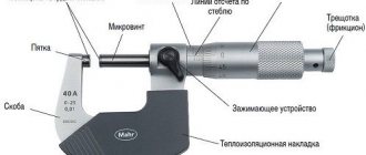
Dependence of current density on cross-section
Even if the correct cross-section of the wire is selected, it can still overheat. There are several reasons: weak contact at the joints or oxidation associated with unacceptable twisting of aluminum and copper conductors.
Wire size
To select the cross-section of the current-carrying core (conductor, and not the entire cable with sheath and insulation), they are guided by two parameters:
- heating within acceptable limits;
- loss of voltage.
Overheating of the underground cable placed in plastic hose tubes is dangerous. In overhead power lines, attention is paid to voltage loss. For combined segments with two different sections, select the larger one, rounding it up to the standard value. Before calculating the cross-section or searching for suitable tabular values, you should determine what the operating conditions will be.
An incorrect choice of cable cross-section can lead to overheating and fire.
To calculate the potential heating, the long-term permissible temperature must be taken into account. The value directly depends on the possible current strength Ip. After using the formula, you will receive the calculated current Iр, which should differ from Iп and be less than its value (in no case more!). When choosing a section, use the following formula:
- Iр = Pн/Un,
Where:
- Pn — rated power, W;
- Un — rated voltage, V.
This formula can be used to calculate currents in conductors with an already established temperature, provided that the cable is not affected by other cooling or warming factors. The value of the continuous permissible current Ip depends on various parameters: cross-section, material of manufacture, insulating shell and installation method.
To check the voltage drop on an overhead power line, use the following formula:
- Up = (U - Un) *100/ Un,
Where:
- U—voltage from the source;
- Un is the voltage at the place where the voltage receiver is connected.
The maximum permissible voltage deviation is 10%.
Current Density
This physical quantity is a vector quantity. To designate it, use the Latin letter J. The calculation formula is as follows:
- J = I/S,
Where:
- I—current strength, A;
- S—cross-sectional area, sq. mm.
Limit current density for aluminum and copper wires
Current density is the volume of current that passes through a conductor of a given cross-section in a certain period of time. Measured in A/sq. mm.
Choosing thickness
Once you have determined the power, you can select the cable thickness. Below we will provide a table of wire cross-sections by power and current for a classic copper wire, since aluminum wires are no longer used for wiring today.
| Cable cross-section, mm | For 220 V | For 380 V | ||
| current, A | power, kWt | current, A | power, kWt | |
| 1,5 | until 17 | 4 | 16 | 10 |
| 2,5 | 26 | 5,5 | 25 | 16 |
| 4 | 37 | 8,2 | 30 | 20 |
| 6 | 45 | 10 | 40 | 25 |
| 10 | 68 | 15 | 50 | 32 |
| 16 | 85 | 18 | 75 | 48 |
Attention:
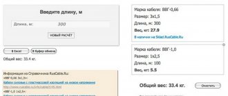
When choosing, keep in mind that most Russian manufacturers save on material, and a 4 mm2 cable may actually end up being 2.5 mm2. Practice shows that such “savings” can reach 40%, so be sure to either measure the cable diameter yourself or purchase it with a reserve.
Now let's look at an example of calculating the wire cross-section based on power consumption. So, we have an abstract kitchen, the power of the appliances is 6 kW. We multiply this figure 6*0.8=4.8 kW. The apartment uses one phase, 220 volts. The closest value (you can only take it as a plus) is 5.5 kW, that is, a cable 2.5 square meters thick. Just in case, we have a reserve of 0.7 kW, which “smoothes out” the savings for producers.
It should also be borne in mind that if the wire is working at its limit, it will heat up quickly. Due to heating to 60-80 degrees, the maximum current is reduced by 10-20 percent, which leads to overload and short circuit. Therefore, for critical sections of the chain, an increased coefficient should be used, multiplying the value not by 0.8, but by 1.2-1.3.
Correct calculation of cable thickness is the key to its long service life
Most often, copper structures with a thickness of 1.5 squares are used for laying lighting systems, for sockets - 2.5 squares, for powerful consumers - 4 or 6 squares (machines are installed at 16, 25, 35 and 45A, respectively). But this use is only suitable for standard apartments or houses that do not have powerful consumers. If you have an electric boiler, boiler, oven or other appliances that consume more than 4 kW, then you need to calculate the cables for each specific case, and not use general recommendations.
The above table of cable cross-sections for power and current uses limit values, so if you get calculated numbers that overlap with encyclopedic ones, then try to take the cable with a reserve. For example, if our kitchen had a power of 7 kW, then 7 * 0.8 = 5.6 kW, which is greater than the value of 5.5 for a 2.5 square cable. Take a cable of 4 squares with a reserve or divide the kitchen into two zones by connecting two 2.5 mm2 cables.
Why do you need to calculate the cable cross-section?
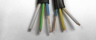
When purchasing a cable, you may see different symbols. For example, a 3x5 wire contains three current-carrying conductors, each of which has a cross-section of 5 square meters. mm. Knowing this, just look at the table of voltage and power.
Only a correctly calculated cross-section guarantees the absence of areas with overheating of the cable. In this case, the wire must withstand temporary loads when the current value is 2-3 times greater than the rated value. You will receive a current reserve, which is important, since at any moment the load on the network may increase due to new household appliances. The absence of heating will prevent spontaneous combustion and fires at objects. This point needs to be thought through in advance, since in most cases a hidden method of installing electrical wiring is used, and the slightest damage can lead to the need to replace the entire line.
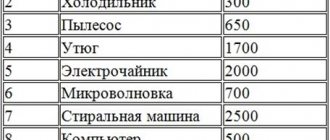
Electrical power of household appliances
Choose by power
The wire cross-section can be selected depending on the maximum current load on the line. Moreover, each household appliance has a different power. The list below shows the capacities of the most common equipment:
- electric stove - 5 kW;
- refrigeration unit - 0.8 kW;
- dishwasher - 2 kW;
- microwave - 1.5 kW;
- kitchen hood - 0.5 kW;
- kettle - 2 kW.
Obviously, the listed electrical appliances are installed in the kitchen. If you add up all the specified numerical values, you can get the total load on the kitchen electrical network. It will be about 12 kW, but the cross-section should be selected with a margin of up to 30%. Ideally, an electrical cable with a cross-section corresponding to a power of 15-16 kW is laid in the kitchen. To connect the equipment you will need at least two sockets.
The table below shows the selection of copper cable by power:
Determination of copper cable cross-section
The voltage of the electrical network is 220 V. Knowing this parameter and the total load, it is enough to use a simple formula to calculate the current consumption:
- I = P/U = 16,000/220 = 72.7 A.
This is the maximum permissible current for the cable being laid, but in fact the household appliances listed above will consume about 56-57 A. However, it is not necessary to exclude situations when other devices will be connected to the network - a vacuum cleaner, additional lamps, and so on. Many electricians avoid calculations using the coefficient 1.3 (30% margin), and simply add another 5 A to the actual value of the permissible current. If this option was possible before, today it is unlikely. Every year this parameter only increases: more powerful refrigerators, washing machines and vacuum cleaners appear.
The table below shows the selection of aluminum cable by power:
Determination of aluminum cable cross-section
Having completed the calculations of the permissible current, proceed to the selection of material for the current-carrying conductors. Aluminum cable costs less than copper cable, but the cross-sectional area of such conductors should be much higher. The current density for aluminum is 8, copper - 10 A/sq. mm.
Normalized current density for cables, A/mm2
Table 3.35
| Cable type | Тmax, h/year | ||
| more than 1000 to 3000 | more than 3000 to 5000 | more than 5000 | |
| Cables with paper, rubber and polyvinyl chloride insulation with conductors: copper aluminum | 2,4 1,3 | 2,0 1D | 1,6 1,0 |
| Cables with rubber and plastic insulation with cores: copper aluminum | 2,8 1,5 | 2,5 1,4 | 2,2 1,3 |
The economic power of the cable line, calculated based on the normalized current density, is given in Table. 3.36 and 3.37.
Current load on the cable: how to calculate the cross-section
The total amount of current moving through a conductor depends on several characteristics: length, width, resistivity and temperature. An increase in temperature is accompanied by a decrease in current. Any reference information that you find in the PUE tables is usually provided for a room temperature of 18 degrees Celsius.
In addition to the electric current, you need to know the conductor material and voltage. The simplest calculation of cable cross-section based on permissible current is to divide its value by 10. If, when studying the table, you do not find the required value, then look for the nearest, slightly larger value. This option is possible for copper wires, and the permissible current is 40 A or less. In the range of 40-80 A, the permissible current should be divided by 8. For aluminum wires, the value is divided by 6. The reason for this was indicated at the end of the previous section.
Permissible current load on the cable
Rule for choosing wire cross-sectional area for maximum current
You can select the required cross-sectional area of the copper wire based on the maximum current using this simple rule:
The required wire cross-sectional area is equal to the maximum current divided by 10.
This rule is given without reserve, back to back, so the result must be rounded up to the nearest standard size. For example, the current is 32 Amps. You need a wire with a cross section of 32/10 = 3.2 mm2. We choose the closest one (naturally, in the larger direction) - 4 mm2. As you can see, this rule fits well into the tabular data.
Important note. This rule works well for currents up to 40 Amps . If the currents are greater (this is already outside the boundaries of an ordinary apartment or house, such currents are at the input) - you need to choose a wire with an even larger margin - divide not by 10, but by 8 (up to 80 A)
The same rule can be stated for finding the maximum current through a copper wire with a known area:
The maximum current is equal to the cross-sectional area multiplied by 10.
And in conclusion - again about the good old aluminum wire.
Aluminum conducts current less well than copper. This is enough to know, but here are some numbers. For aluminum (the same cross-section as the copper wire) at currents up to 32 A, the maximum current will be only 20% less than for copper. At currents up to 80 A, aluminum conducts current 30% worse.
For aluminum the rule of thumb would be:
The maximum current of an aluminum wire is equal to the cross-sectional area multiplied by 6.
I believe that the knowledge given in this article is quite enough to choose a wire based on the ratios “price/thickness”, “thickness/operating temperature” and “thickness/maximum current and power”.
That’s basically all I wanted to tell you about the cross-sectional area of the wires . If something is not clear or you have something to add, ask and write in the comments. If you are interested in what I will publish next on the SamElectric blog, subscribe to receive new articles.
Calculation of cable cross-section by power and length
The length of the cable determines the voltage loss. One potential unpleasant situation: at the end of the selected wire, the voltage has decreased to a minimum, which is not enough to ensure the functionality of the equipment. In household electrical networks, losses will be small, so they can be neglected. It is enough to use a cable with a margin of 100-150 mm, which is necessary to simplify switching. If the edges of the wire are connected to the electrical panel, then the margin should be higher, since the installation of automatic machines is required.
When placing the cable over longer sections, you need to take into account the voltage drop, which is calculated using the formula given above. Any conductor has a certain electrical resistance, which depends on a number of characteristics:
- Wire length, m. The longer the length, the higher the losses.
- Cross-sectional area, sq. mm. The higher the parameter, the lower the voltage drop.
- Specific resistance of the material (look in reference books).
Maximum cable length for various current loads
To calculate the voltage drop in normal cases, it is enough to multiply the resistance and the permissible current. The actual value may be greater, but not more than 5%. If it does not fit within the specified framework, you will have to use a cable with a larger cross-section.
To calculate the cable cross-section for power and length, proceed as follows:
- Calculate the current using the formula I=P/(U*cosph), where P is power, U is voltage, cosph is coefficient. In household electrical networks, this coefficient is equal to 1, so the formula simplifies to I=P/U. In industry, cosph is the ratio of active and apparent power (active and reactive).
- In the PUE table, find a suitable cable cross-section depending on the current.
- Calculate the conductor resistance using the formula: R=ρ*l/S, where ρ is the resistivity of the material from which the conductors are made, l is the cable length, S is the cross-sectional area. Remember that electric current flows in both directions, so the total resistance is equal to twice the value obtained from the formula above.
- For voltage drop, use the formula ΔU=I*R
- To get the percentage voltage drop, divide ΔU/U.
Thus, if the final value does not exceed 5%, you can leave the cable with the selected cross-section. Otherwise, it will have to be replaced with a conductor with an increased cross-section.
Continuously permissible currents
This value differs depending on the selected cable and the current-carrying cores used. Any wire has a certain long-term temperature Td, which is indicated in its passport. At this temperature, prolonged operation of the conductor cores is permissible, and any damage is excluded.
To calculate the continuous permissible current, use the formula:
- Id = √((Td*S*Kt)/R),
Where:
- Ktp - heat transfer coefficient;
- R - resistance;
- S - core section.
In practice, you can use PUE tables.
Continuously permissible currents for copper wires and cables
Load table for cable cross-section
The transmission and distribution of electrical energy is completely impossible without wires and cables. It is with their help that electric current is supplied to consumers. Under these conditions, the current load across the cable cross-section, calculated using formulas or determined using tables, becomes of great importance. In this regard, cable cross-sections are selected in accordance with the load created by all electrical appliances.
Preliminary calculations and selection of cross-section ensure uninterrupted passage of electric current. For these purposes, there are tables with a wide range of mutual relationships between the cross section and power and current. They are used even at the stage of development and design of electrical networks, which makes it possible to subsequently eliminate emergency situations that entail significant costs for the repair and restoration of cables, wires and equipment.
The existing table of cable current loads given in the PUE shows that a gradual increase in the conductor cross-section causes a decrease in current density (A/mm2). In some cases, instead of one cable with a large cross-sectional area, it will be more rational to use several cables with a smaller cross-section. However, this option requires economic calculations, since with a noticeable saving in non-ferrous core metal, the costs of installing additional cable lines increase.
Open and closed wiring
Electrical wiring can be of two types:
- closed;
- open.
In most cases, hidden installation is used for apartments. Using a hammer drill or wall chaser, special recesses are created in the wall or ceiling into which the cable is laid. Additionally, it can be placed in corrugated tubes or sleeves. Having hidden the cable, the recesses should be sealed with plaster. The only acceptable option for modern hidden wiring is copper conductors. In this case, you should consider in advance the potential expansion of the network or the process of partial replacement of its components. Ideally, you should use flat wires.
Laying hidden wiring in grooves
Open electrical wiring involves placing the cable along surfaces. Mainly flexible conductors with a round cross-section are used. They are placed in cable ducts or passed through corrugations. When calculating the load, the cable laying method must be taken into account.
Selection of wire cross-section according to the number of consumers
When calculating cross-sections for an electrical cable in an apartment, it is first recommended to show the wiring schematically. The drawing must indicate all devices that consume electricity. The circuit is divided into different rooms, since each can use a wire of a different cross-section.
Wiring diagram for consumers
The electrical network is divided into several circuits. Each circuit corresponds only to those electrical appliances that are connected to it. To select a cable connecting all circuits, you need to calculate the total total power. This is the main criterion for choosing a section. Each subsequent branching (branch) will lead to a decrease in the total power and, accordingly, a decrease in the required cross-section.
Current loads in DC networks
When calculating the current load in a direct current network, they are guided by a single-core cable. The voltage of this current is 12 V. Calculation of the load of the wire through which a 0.1 kW light bulb is connected (for example, in the headlight of a car) looks like this:
- I = P/U = 100/12 ~ 8.35 A.
After this, it is easy to calculate the resistance:
- R = U/I = 12/8.35 = 1.44 Ohm.
In the table, find the resistivity of copper, from which the cores of modern conductors are made. Also assume that the cable length is 2 m. Use the formula given in the sections above to obtain the cross-sectional area of the suitable wire:
- S = (ρ*L)/R = (1.68*10-8*2)/1.44 = 1.2 sq. mm.
Selecting a cable cross-section for DC networks
When studying the PUE, you can find countless tables that define the current load for AC networks with single- and three-phase circuits. Therefore, it is not necessary to perform such complex calculations.
Electrical laboratory » Questions and answers » PUE 7th edition » 1.3.10 - 1.3.11. Permissible continuous currents for wires, cords and cables with rubber or plastic insulation
PERMISSIBLE CONTINUOUS CURRENTS FOR WIRES, CORDS AND CABLES WITH RUBBER OR PLASTIC INSULATION
1.3.10. Permissible long-term currents for wires with rubber or polyvinyl chloride insulation, cords with rubber insulation and cables with rubber or plastic insulation in lead, polyvinyl chloride and rubber sheaths are given in Table. 1.3.4-1.3.11. They are accepted for temperatures: cores +65, ambient air +25 and ground + 15°C. When determining the number of wires laid in one pipe (or cores of a stranded conductor), the neutral working conductor of a four-wire three-phase current system, as well as grounding and neutral protective conductors are not taken into account. The data contained in the table. 1.3.4 and 1.3.5 should be applied regardless of the number of pipes and the location of their installation (in the air, floors, foundations). Permissible long-term currents for wires and cables laid in boxes, as well as in trays in bundles, must be accepted: for wires - according to table. 1.3.4 and 1.3.5 as for wires laid in pipes, for cables - according to table. 1.3.6-1.3.8 as for cables laid in the air. If the number of simultaneously loaded wires is more than four, laid in pipes, boxes, and also in trays in bundles, the currents for the wires should be taken according to the table. 1.3.4 and 1.3.5 as for wires laid openly (in the air), with the introduction of reduction factors of 0.68 for 5 and 6; 0.63 for 7-9 and 0.6 for 10-12 conductors. For secondary circuit wires, reduction factors are not introduced.
Table 1.3.4. Permissible continuous current for wires and cords with rubber and polyvinyl chloride insulation with copper conductors
| Section conductive cores, mm2 | Current, A, for wires laid | |||||
| open | in one pipe | |||||
| two single-core | three single-core | four single-core | one two-core | one three-wire | ||
| 0,5 | 11 | — | — | — | — | — |
| 0,75 | 15 | — | — | — | — | — |
| 1 | 17 | 16 | 15 | 14 | 15 | 14 |
| 1,2 | 20 | 18 | 16 | 15 | 16 | 14,5 |
| 1,5 | 23 | 19 | 17 | 16 | 18 | 15 |
| 2 | 26 | 24 | 22 | 20 | 23 | 19 |
| 2,5 | 30 | 27 | 25 | 25 | 25 | 21 |
| 3 | 34 | 32 | 28 | 26 | 28 | 24 |
| 4 | 41 | 38 | 35 | 30 | 32 | 27 |
| 5 | 46 | 42 | 39 | 34 | 37 | 31 |
| 6 | 50 | 46 | 42 | 40 | 40 | 34 |
| 8 | 62 | 54 | 51 | 46 | 48 | 43 |
| 10 | 80 | 70 | 60 | 50 | 55 | 50 |
| 16 | 100 | 85 | 80 | 75 | 80 | 70 |
| 25 | 140 | 115 | 100 | 90 | 100 | 85 |
| 35 | 170 | 135 | 125 | 115 | 125 | 100 |
| 50 | 215 | 185 | 170 | 150 | 160 | 135 |
| 70 | 270 | 225 | 210 | 185 | 195 | 175 |
| 95 | 330 | 275 | 255 | 225 | 245 | 215 |
| 120 | 385 | 315 | 290 | 260 | 295 | 250 |
| 150 | 440 | 360 | 330 | — | — | — |
| 185 | 510 | — | — | — | — | — |
| 240 | 605 | — | — | — | — | — |
| 300 | 695 | — | — | — | — | — |
| 400 | 830 | — | — | — | — | — |
Table 1.3.5. Permissible continuous current for rubber and polyvinyl chloride insulated wires with aluminum conductors
| Section conductive cores, mm2 | Current, A, for wires laid | |||||
| open | in one pipe | |||||
| two single-core | three single-core | four single-core | one-two-core | one three-wire | ||
| 2 | 21 | 19 | 18 | 15 | 17 | 14 |
| 2,5 | 24 | 20 | 19 | 19 | 19 | 16 |
| 3 | 27 | 24 | 22 | 21 | 22 | 18 |
| 4 | 32 | 28 | 28 | 23 | 25 | 21 |
| 5 | 36 | 32 | 30 | 27 | 28 | 24 |
| 6 | 39 | 36 | 32 | 30 | 31 | 26 |
| 8 | 46 | 43 | 40 | 37 | 38 | 32 |
| 10 | 60 | 50 | 47 | 39 | 42 | 38 |
| 16 | 75 | 60 | 60 | 55 | 60 | 55 |
| 25 | 105 | 85 | 80 | 70 | 75 | 65 |
| 35 | 130 | 100 | 95 | 85 | 95 | 75 |
| 50 | 165 | 140 | 130 | 120 | 125 | 105 |
| 70 | 210 | 175 | 165 | 140 | 150 | 135 |
| 95 | 255 | 215 | 200 | 175 | 190 | 165 |
| 120 | 295 | 245 | 220 | 200 | 230 | 190 |
| 150 | 340 | 275 | 255 | — | — | — |
| 185 | 390 | — | — | — | — | — |
| 240 | 465 | — | — | — | — | — |
| 300 | 535 | — | — | — | — | — |
| 400 | 645 | — | — | — | — | — |
Table 1.3.6. Permissible continuous current for wires with copper conductors with rubber insulation in metal protective sheaths and cables with copper conductors with rubber insulation in lead, polyvinyl chloride, nayrite or rubber sheaths, armored and unarmored
| Section conductive cores, mm2 | Current *, A, for wires and cables | ||||
| single-core | two-wire | three-wire | |||
| when laying | |||||
| in the air | in the air | in the ground | in the air | in the ground | |
| 1,5 | 23 | 19 | 33 | 19 | 27 |
| 2,5 | 30 | 27 | 44 | 25 | 38 |
| 4 | 41 | 38 | 55 | 35 | 49 |
| 6 | 50 | 50 | 70 | 42 | 60 |
| 10 | 80 | 70 | 105 | 55 | 90 |
| 16 | 100 | 90 | 135 | 75 | 115 |
| 25 | 140 | 115 | 175 | 95 | 150 |
| 35 | 170 | 140 | 210 | 120 | 180 |
| 50 | 215 | 175 | 265 | 145 | 225 |
| 70 | 270 | 215 | 320 | 180 | 275 |
| 95 | 325 | 260 | 385 | 220 | 330 |
| 120 | 385 | 300 | 445 | 260 | 385 |
| 150 | 440 | 350 | 505 | 305 | 435 |
| 185 | 510 | 405 | 570 | 350 | 500 |
| 240 | 605 | — | — | — | — |
___________ * Currents apply to wires and cables both with and without a neutral core.
Table 1.3.7. Permissible continuous current for cables with aluminum conductors with rubber or plastic insulation in lead, polyvinyl chloride and rubber sheaths, armored and unarmored
| Section conductive cores, mm2 | Current, A, for cables | ||||
| single-core | two-wire | three-wire | |||
| when laying | |||||
| in the air | in the air | in the ground | in the air | in the ground | |
| 2,5 | 23 | 21 | 34 | 19 | 29 |
| 4 | 31 | 29 | 42 | 27 | 38 |
| 6 | 38 | 38 | 55 | 32 | 46 |
| 10 | 60 | 55 | 80 | 42 | 70 |
| 16 | 75 | 70 | 105 | 60 | 90 |
| 25 | 105 | 90 | 135 | 75 | 115 |
| 35 | 130 | 105 | 160 | 90 | 140 |
| 50 | 165 | 135 | 205 | 110 | 175 |
| 70 | 210 | 165 | 245 | 140 | 210 |
| 95 | 250 | 200 | 295 | 170 | 255 |
| 120 | 295 | 230 | 340 | 200 | 295 |
| 150 | 340 | 270 | 390 | 235 | 335 |
| 185 | 390 | 310 | 440 | 270 | 385 |
| 240 | 465 | — | — | — | — |
Note. Permissible continuous currents for four-core cables with plastic insulation for voltages up to 1 kV can be selected according to table. 1.3.7, as for three-core cables, but with a coefficient of 0.92.
Table 1.3.8. Permissible continuous current for portable light and medium hose cords, portable heavy duty hose cables, mine flexible hose cables, floodlight cables and portable wires with copper conductors
| Conductive cross-section cores, mm2 | Current *, A, for cords, wires and cables | ||
| single-core | two-wire | three-wire | |
| 0,5 | — | 12 | — |
| 0,75 | — | 16 | 14 |
| 1,0 | — | 18 | 16 |
| 1,5 | — | 23 | 20 |
| 2,5 | 40 | 33 | 28 |
| 4 | 50 | 43 | 36 |
| 6 | 65 | 55 | 45 |
| 10 | 90 | 75 | 60 |
| 16 | 120 | 95 | 80 |
| 25 | 160 | 125 | 105 |
| 35 | 190 | 150 | 130 |
| 50 | 235 | 185 | 160 |
| 70 | 290 | 235 | 200 |
________________ * Currents refer to cords, wires and cables with and without a neutral core
Table 1.3.9. Permissible continuous current for portable hose cables with copper conductors and rubber insulation for peat enterprises
| Conductive cross-section cores, mm2 | Current *, A, for cables with voltage, kV | ||
| 0,5 | 3 | 6 | |
| 6 | 44 | 45 | 47 |
| 10 | 60 | 60 | 65 |
| 16 | 80 | 80 | 85 |
| 25 | 100 | 105 | 105 |
| 35 | 125 | 125 | 130 |
| 50 | 155 | 155 | 160 |
| 70 | 190 | 195 | — |
_____________ * Currents refer to cables with and without a neutral core.
Table 1.3.10. Permissible continuous current for hose cables with copper conductors and rubber insulation for mobile electrical receivers
| Section conductive cores, mm2 | Current *, A, for cables with voltage, kV | Conductor cross-section, mm2 | Current *, A, for cables with voltage, kV | ||
| 3 | 6 | 3 | 6 | ||
| 16 | 85 | 90 | 70 | 215 | 220 |
| 25 | 115 | 120 | 95 | 260 | 265 |
| 35 | 140 | 145 | 120 | 305 | 310 |
| 50 | 175 | 180 | 150 | 345 | 350 |
__________________ * Currents refer to cables with and without a neutral core.
Table 1.3.11. Permissible continuous current for wires with copper conductors with rubber insulation for electrified transport 1.3 and 4 kV
| Conductor cross-section, mm2 | Current, A | Conductor cross-section, mm2 | Current, A | Conductor cross-section, mm2 | Current, A |
| 1 | 20 | 16 | 115 | 120 | 390 |
| 1,5 | 25 | 25 | 150 | 150 | 445 |
| 2,5 | 40 | 35 | 185 | 185 | 505 |
| 4 | 50 | 50 | 230 | 240 | 590 |
| 6 | 65 | 70 | 285 | 300 | 670 |
| 10 | 90 | 95 | 340 | 350 | 745 |
Table 1.3.12. Reduction factor for wires and cables laid in boxes
| Way | Number of laid wires and cables | Reduction factor for power supply wires | ||
| gaskets | single-core | stranded | separate electrical receivers with a utilization factor of up to 0.7 | groups of electrical receivers and individual receivers with a utilization factor of more than 0.7 |
| Multilayer and bunches | — | Up to 4 | 1,0 | — |
| 2 | 5-6 | 0,85 | — | |
| 3-9 | 7-9 | 0,75 | — | |
| 10-11 | 10-11 | 0,7 | — | |
| 12-14 | 12-14 | 0,65 | — | |
| 15-18 | 15-18 | 0,6 | — | |
| Single layer | 2-4 | 2-4 | — | 0,67 |
| 5 | 5 | — | 0,6 | |
1.3.11. Permissible long-term currents for wires laid in trays, when laid single-row (not in bundles), should be taken as for wires laid in the air. Permissible long-term currents for wires and cables laid in boxes should be taken according to table. 1.3.4-1.3.7 as for single wires and cables laid openly (in the air), using the reduction factors indicated in table. 1.3.12. When choosing reduction factors, control and reserve wires and cables are not taken into account.
Causes of cable heating
Current-carrying conductors can overheat for several reasons, which are directly related to the nature of the electric current. The electric field sets in motion electrons, which move along the selected conductor. In the crystal lattices of which metals are composed, strong molecular bonds operate. Imagine a table tennis ball and a spider web. The second one is more or less durable, the first one is light in weight, so in order for the ball to break the web, more effort will have to be made. The harder you swing, the more tense your muscles will be. The higher the voltage, the higher the energy expended. Accordingly, the muscles will heat up more.
Likewise, electrons are forced to release more heat, spending a lot of energy to overcome these molecular bonds. This process is called the conversion of electrical energy into thermal energy.
This phenomenon can be compared with the release of heat during friction. We can say that electrons are forced to rub against the crystal lattice of the metal and thereby generate heat. This property of a metal cable has its advantages and disadvantages. Heating can be useful in manufacturing facilities and for household appliances. It is the main property that allows electric stoves, heaters, irons and kettles to operate. However, in conventional electrical networks this can lead to overheating and destruction of the insulation, and subsequently even to a fire. Machinery and equipment may deteriorate. A similar thing happens if the specified norm for long-term current loads is exceeded.
We list three main reasons for conductor overheating:
- The most common is the use of a cable with an incorrect cross-section. Any conductor has a unique maximum current carrying capacity. It is measured in Amperes. Before connecting a household appliance, you need to determine its power and, in accordance with it, select the correct cross-section. It is important to take into account a margin of 30-40%.
- The second reason is the lack of high-quality contact at the connection points of the line. We are talking about sections of the route where the cable is connected to a panel, circuit breaker or switch. Poor contact leads to heating. In worst case scenarios - complete burnout. In most cases, it will be enough to inspect the contacts and tighten all connections.
- The old electrical wiring was built on aluminum conductors, so when modernizing such cable lines there is often a need to switch to copper conductors. In this case, it is important to follow the technique for connecting copper and aluminum conductors. Without the use of special terminal blocks, the appearance of oxidation is a matter of time.
Old aluminum wiring in the apartment
Calculation of permissible current for heating cores
If a conductor of a suitable cross-section is selected, this will eliminate voltage drop and overheating of the line. Thus, the cross-section determines how optimal and economical the operating mode of the electrical network will be. It would seem that you can simply take and install a cable with a huge cross-section. But the cost of copper conductors is proportional to their cross-section, and the difference when installing electrical wiring in just one room can amount to several thousand rubles. Therefore, it is important to be able to correctly calculate the cable cross-section: on the one hand, you guarantee the safe operation of the network, on the other hand, you will not spend extra money on purchasing an overly “thick” conductor.
To select the wire cross-section, two important criteria must be taken into account - permissible heating and voltage loss. Having received two values for the cross-sectional area of the conductor using different formulas, choose the larger value, rounding it to the standard. Overhead power lines are especially sensitive to voltage loss. At the same time, for underground lines and cables placed in corrugated pipes, it is important to take into account the permissible heating. Thus, the cross-section should be determined depending on the type of wiring.
Permissible heating temperatures of current-carrying cable cores
Id - permissible load on the cable (heating current). This value corresponds to the current flowing through the conductor over a long period of time. In the process of this, a set, long-term permissible temperature (Td) appears. The calculated current strength (Ip) must correspond to the permissible current (Id), and to determine it you need to use the formula:
- Iр=(1000*Pн*kз)/√(3*Un*hд*cos j),
Where:
- Pn — rated power, kW;
- Kz - load factor (0.85-0.9);
- Un — rated voltage of the equipment;
- hd - equipment efficiency;
- cos j - equipment power factor (0.85-0.92).
It turns out that for any long-term permissible current flowing through the conductor, there corresponds a specific value of the established, long-term permissible heating temperature. It is important to neutralize the influence of other environmental factors. The cable current directly depends on the material from which the insulation is made, the laying method, the cross-section and material of the cores in the conductor.
Even if we take into account the same current values, the thermal output will be different depending on the ambient temperature. The lower the temperature, the more efficient the heat transfer.
Cable correction factors depending on ambient temperature
Temperatures differ depending on the region and time of year, so in the PUE you can find tables for specific values. If the temperature differs significantly from the calculated one, correction factors will have to be used. The base temperature indoors or outdoors is 25 degrees Celsius. If the cable is laid underground, the temperature changes by 15 degrees Celsius. However, it is underground that it remains constant.
Permissible continuous currents for wires, cords and cables with rubber or plastic insulation
Permissible continuous currents for wires with rubber or polyvinyl chloride insulation, cords with rubber insulation and cables with rubber or plastic insulation in lead, polyvinyl chloride and rubber sheaths
- Permissible continuous current for wires and cords with rubber and polyvinyl chloride insulation with copper conductors
- Permissible continuous current for rubber and polyvinyl chloride insulated wires with aluminum conductors
- Permissible continuous current for wires with copper conductors with rubber insulation in metal protective sheaths and cables with copper conductors with rubber insulation in lead, polyvinyl chloride, nayrite or rubber sheaths, armored and unarmored
- Permissible continuous current for cables with aluminum conductors with rubber or plastic insulation in lead, polyvinyl chloride and rubber sheaths, armored and unarmored
- Permissible continuous current for portable light and medium hose cords, portable heavy duty hose cables, mine flexible hose cables, floodlight cables and portable wires with copper conductors
- Permissible continuous current for portable hose cables with copper conductors and rubber insulation for peat enterprises
- Permissible continuous current for hose cables with copper conductors and rubber insulation for mobile electrical receivers
- Permissible continuous current for wires with copper conductors with rubber insulation for electrified transport 1, 3 and 4 kV
Permissible continuous current for wires and cords with rubber and polyvinyl chloride insulation with copper conductors
| Conductor cross-section, mm2 | Current, A, for wires laid | |||||
| open | in one pipe | |||||
| two single core | three single core | four single core | one two core | one three core | ||
| 0,5 | 11 | — | — | — | — | — |
| 0,75 | 15 | — | — | — | — | — |
| 1 | 17 | 16 | 15 | 14 | 15 | 14 |
| 1,2 | 20 | 18 | 16 | 15 | 16 | 14,5 |
| 1,5 | 23 | 19 | 17 | 16 | 18 | 15 |
| 2 | 26 | 24 | 22 | 20 | 23 | 19 |
| 2,5 | 30 | 27 | 25 | 25 | 25 | 21 |
| 3 | 34 | 32 | 28 | 26 | 28 | 24 |
| 4 | 41 | 38 | 35 | 30 | 32 | 27 |
| 5 | 46 | 42 | 39 | 34 | 37 | 31 |
| 6 | 50 | 46 | 42 | 40 | 40 | 34 |
| 8 | 62 | 54 | 51 | 46 | 48 | 43 |
| 10 | 80 | 70 | 60 | 50 | 55 | 50 |
| 16 | 100 | 85 | 80 | 75 | 80 | 70 |
| 25 | 140 | 115 | 100 | 90 | 100 | 85 |
| 35 | 170 | 135 | 125 | 115 | 125 | 100 |
| 50 | 215 | 185 | 170 | 150 | 160 | 135 |
| 70 | 270 | 225 | 210 | 185 | 195 | 175 |
| 95 | 330 | 275 | 255 | 225 | 245 | 215 |
| 120 | 385 | 315 | 290 | 260 | 295 | 250 |
| 150 | 440 | 360 | 330 | — | — | — |
| 185 | 510 | — | — | — | — | — |
| 240 | 605 | — | — | — | — | — |
| 300 | 695 | — | — | — | — | — |
| 400 | 830 | — | — | — | — | — |
Permissible continuous current for rubber and polyvinyl chloride insulated wires with aluminum conductors
| Conductor cross-section, mm2 | Current, A, for wires laid | |||||
| open | in one pipe | |||||
| two single-core | three single-core | four single-core | one two-wire | one three-wire | ||
| 2 | 21 | 19 | 18 | 15 | 17 | 14 |
| 2,5 | 24 | 20 | 19 | 19 | 19 | 16 |
| 3 | 27 | 24 | 22 | 21 | 22 | 18 |
| 4 | 32 | 28 | 28 | 23 | 25 | 21 |
| 5 | 36 | 32 | 30 | 27 | 28 | 24 |
| 6 | 39 | 36 | 32 | 30 | 31 | 26 |
| 8 | 46 | 43 | 40 | 37 | 38 | 32 |
| 10 | 60 | 50 | 47 | 39 | 42 | 38 |
| 16 | 75 | 60 | 60 | 55 | 60 | 55 |
| 25 | 105 | 85 | 80 | 70 | 75 | 65 |
| 35 | 130 | 100 | 95 | 85 | 95 | 75 |
| 50 | 165 | 140 | 130 | 120 | 125 | 105 |
| 70 | 210 | 175 | 165 | 140 | 150 | 135 |
| 95 | 255 | 215 | 200 | 175 | 190 | 165 |
| 120 | 295 | 245 | 220 | 200 | 230 | 190 |
| 150 | 340 | 275 | 255 | — | — | — |
| 185 | 390 | — | — | — | — | — |
| 240 | 465 | — | — | — | — | — |
| 300 | 535 | — | — | — | — | — |
| 400 | 645 | — | — | — | — | — |
Permissible continuous current for wires with copper conductors with rubber insulation in metal protective sheaths and cables with copper conductors with rubber insulation in lead, polyvinyl chloride, nayrite or rubber sheaths, armored and unarmored
| Conductor cross-section, mm2 | Current, A, for wires and cables | ||||
| single-core | two-wire | three-wire | |||
| when laying | |||||
| in the air | in the air | in the ground | in the air | in the ground | |
| 1,5 | 23 | 19 | 33 | 19 | 27 |
| 2,5 | 30 | 27 | 44 | 25 | 38 |
| 4 | 41 | 38 | 55 | 35 | 49 |
| 6 | 50 | 50 | 70 | 42 | 60 |
| 10 | 80 | 70 | 105 | 55 | 90 |
| 16 | 100 | 90 | 135 | 75 | 115 |
| 25 | 140 | 115 | 175 | 95 | 150 |
| 35 | 170 | 140 | 210 | 120 | 180 |
| 50 | 215 | 175 | 265 | 145 | 225 |
| 70 | 270 | 215 | 320 | 180 | 275 |
| 95 | 325 | 260 | 385 | 220 | 330 |
| 120 | 385 | 300 | 445 | 260 | 385 |
| 150 | 440 | 350 | 505 | 305 | 435 |
| 185 | 510 | 405 | 570 | 350 | 500 |
| 240 | 605 | — | — | — | — |
* Currents apply to wires and cables both with and without a neutral core.
Permissible continuous current for cables with aluminum conductors with rubber or plastic insulation in lead, polyvinyl chloride and rubber sheaths, armored and unarmored*
| Conductor cross-section, mm2 | Current, A, for wires and cables | ||||
| single-core | two-wire | three-wire | |||
| when laying | |||||
| in the air | in the air | in the ground | in the air | in the ground | |
| 2,5 | 23 | 21 | 34 | 19 | 29 |
| 4 | 31 | 29 | 42 | 27 | 38 |
| 6 | 38 | 38 | 55 | 32 | 46 |
| 10 | 60 | 55 | 80 | 42 | 70 |
| 16 | 75 | 70 | 105 | 60 | 90 |
| 25 | 105 | 90 | 135 | 75 | 115 |
| 35 | 130 | 105 | 160 | 90 | 140 |
| 50 | 165 | 135 | 205 | 110 | 175 |
| 70 | 210 | 165 | 245 | 140 | 210 |
| 95 | 250 | 200 | 295 | 170 | 255 |
| 120 | 295 | 230 | 340 | 200 | 295 |
| 150 | 340 | 270 | 390 | 235 | 335 |
| 185 | 390 | 310 | 440 | 270 | 385 |
| 240 | 465 | — | — | — | — |
*Note. Permissible continuous currents for four-core cables with plastic insulation for voltages up to 1 kV can be selected as for three-core cables, but with a coefficient of 0.92.
Permissible continuous current for portable light and medium hose cords, portable heavy duty hose cables, mine flexible hose cables, floodlight cables and portable wires with copper conductors
| Conductor cross-section, mm2 | Current, A, for cords, wires and cables | ||
| single-core | two-wire | three-wire | |
| 0,5 | — | 12 | — |
| 0,75 | — | 16 | 14 |
| 1,0 | — | 18 | 16 |
| 1,5 | — | 23 | 20 |
| 2,5 | 40 | 33 | 28 |
| 4 | 50 | 43 | 36 |
| 6 | 65 | 55 | 45 |
| 10 | 90 | 75 | 60 |
| 16 | 120 | 95 | 80 |
| 25 | 160 | 125 | 105 |
| 35 | 190 | 150 | 130 |
| 50 | 235 | 185 | 160 |
| 70 | 290 | 235 | 200 |
* Currents apply to cords, wires and cables with and without a neutral core.
Permissible continuous current for portable hose cables with copper conductors and rubber insulation for peat enterprises
| Conductor cross-section, mm2 | Current, A, for cables with voltage, kV | ||
| 0,5 | 3 | 6 | |
| 6 | 44 | 45 | 47 |
| 10 | 60 | 60 | 65 |
| 16 | 80 | 80 | 85 |
| 25 | 100 | 105 | 105 |
| 35 | 125 | 125 | 130 |
| 50 | 155 | 155 | 160 |
| 70 | 190 | 195 | — |
* Currents refer to cables with and without a neutral core.
Permissible continuous current for hose cables with copper conductors and rubber insulation for mobile electrical receivers
| Conductor cross-section, mm2 | Current, A, for cables with voltage, kV | Conductor cross-section, mm2 | Current*, A, for cables with voltage, kV | ||
| 3 | 6 | 3 | 6 | ||
| 16 | 85 | 90 | 70 | 215 | 220 |
| 25 | 115 | 120 | 95 | 260 | 265 |
| 35 | 140 | 145 | 120 | 305 | 310 |
| 50 | 175 | 180 | 150 | 345 | 350 |
* Currents refer to cables with and without a neutral core.
Permissible continuous current for wires with copper conductors with rubber insulation for electrified transport 1, 3 and 4 kV
| Conductor cross-section, mm2 | Current, A | Conductor cross-section, mm2 | Current, A | Conductor cross-section, mm2 | Current, A |
| 1 | 20 | 16 | 115 | 120 | 390 |
| 1,5 | 25 | 25 | 150 | 150 | 445 |
| 2,5 | 40 | 35 | 185 | 185 | 505 |
| 4 | 50 | 50 | 230 | 240 | 590 |
| 6 | 65 | 70 | 285 | 300 | 670 |
| 10 | 90 | 95 | 340 | 350 | 745 |
Heat transfer conditions
An important condition for heat transfer is the humid environment in which the cable is located. When placing a wire in the ground, heat removal is directly related to the structure and its composition, as well as the level of humidity.
To obtain the most accurate values, you will have to analyze the composition of the soil, depending on which the resistance will vary. Using the table, look for resistivity. Thanks to high-quality compaction, this characteristic can be reduced. Sand and gravel have lower thermal conductivity compared to clay, so ideally the wires are buried last. Instead of clay, you can use loam without admixtures of slag, stones and debris.
The heat dissipation of the air cable is minimal. The parameter decreases for lines in cable ducts that have an air gap. Cables located close to each other heat each other, so current loads should be kept as low as possible. Permissible currents are calculated using two different formulas depending on the operating mode - emergency or long-term. If a short circuit occurs, the permissible temperature for a paper-insulated wire is 200, PVC - 120 degrees Celsius.
It is important to remember the different cooling conditions for cables with and without insulation. In the first case, the heat flows emanating from the heating of the cores are forced to overcome an additional barrier in the form of an insulating layer.
Cable location in trench
When laying cables underground, when two conductors are located in one trench at once, the cooling process will slow down significantly, which will lead to a reduction in permissible current loads.
From the point of view of electrical and fire safety, determining the correct long-term permissible current and cable cross-section is an important condition to prevent overheating, insulation failure and ignition of the cable line. When making calculations, you should be careful and take into account many additional conditions. Certain adjustments are needed even for tabular values.