Cable line tests are carried out at the following intervals:
- annually - for power supply and distribution lines with rubber insulation, serving life support facilities of populated areas and other important consumers;
- every 3 years - for main supply lines 6–35 kV;
- every 5 years - for backup lines.
- Extraordinary - in case of emergency shutdown of electrical equipment.
Cable testing with increased voltage is carried out to assess the compliance of the resistance value, absorption coefficient and other parameters of the insulating sheath with established standards. During testing, defects are identified that can provoke an accident and failure of expensive electrical equipment.
Pass or fail the test
Testing
A cable test is generally considered to have passed perfectly if:
- the process was carried out without breakdowns, also if the surface discharges were not blocked from the outside;
- the current flowing out during the test does not increase in its indicators;
- the value shown by the resistance on the cable insulation did not change downward.
We often have to deal with the fact that the currents flowing during testing can have a value that is an order of magnitude greater than those indicated in the tables as standard. If this happens, the cable can be used, but its service life will be significantly reduced.
Test conditions
4.1. Testing of cable power lines up to 10 kV is permitted only at positive temperatures. During the cold period (in the cold), frost or ice may appear inside the insulation (in the cable structure). This situation does not allow obtaining reliable parameters, since frozen water particles are a dielectric.
4.2. Before starting tests, check the humidity and presence of condensation on the power cable cores. The presence of water particles can trigger an insulation breakdown, which can lead to failure of not only the electrical installations or other equipment being tested, but also the testing equipment.
4.3. Before testing, thoroughly clean the cable funnels from dust, moisture and other contaminants.
4.4. Atmospheric pressure does not affect the current SCR parameters. In this case, its value must be recorded in the test report.
Purpose
1.1.
The Testing Instructions (TIP) have been developed as a guide for specialized employees performing electrical testing of electrical installations. 1.2. This document defines the procedure for testing SCL (power cable lines) up to 10 kV.
1.3. SCL tests are carried out in accordance with the requirements:
- Ch. 1.8.37 PUE-7;
- Ch. 2.4 Appendix 3.1 Tables 10,11 PTEEP-2019;
- Ch. 29 tables 29.1, 29.211 RD34.45-51.300-97 “Scope and standards for testing electrical equipment.”
1.4. The purpose of the tests is to test the compliance of the measured parameters of SCL or electrical installations with the requirements of PUE-7.
Determination of the electrical working capacitance of the cores.
Produced for lines 35 kV and above. The measured capacity, reduced to specific values, should not differ from the factory test results by more than 5%.
The capacitance of cable lines is measured using an ammeter-voltmeter method or a bridge circuit.
Ammeter-voltmeter method. allows you to accurately determine capacitances with values of C≥0.1 µF, which corresponds to the parameters of the cables. The measurement scheme for this method is shown in Fig. 2.
Based on the results of measuring voltage and current, the capacitance, μF, is calculated using the formula
where: I - capacitive current, A; U is the voltage on the cable, V; f is the frequency of the network voltage, Hz.
Based on the measurement data, the specific capacitance of the cable is determined, μF/km
In the case when measurement by the ammeter-voltmeter method requires special equipment and instruments, it is desirable to use the bridge method.
When measuring with the bridge method, alternating current bridges such as MD-16, P5026, P595, etc. are used. Measurements are made using an inverted circuit (the instructions for the measurement procedure should be followed). When choosing measuring instruments, it should be taken into account that the specific linear capacitance of cables of 35 kV and above is tenths of μF/km, and the limits for measuring capacitance with AC bridges are in the ranges:
bridge P5026 at a voltage of 3-10 kV - 10 ÷ 1 µF, at a voltage less than 100 V - 6.5 10-4 ÷ 5 10 2 µF;
MD-16 bridge at a voltage of 6-10 kV - 0.3 10-4 ÷0.4 µF, at a voltage of 100 V - 0.3 10-3 ÷100 µF;
bridge P595 at a voltage of 3-10 kV –3 10-5 ÷1 µF, at a voltage less than 100 V – 3 10-4 ÷102 µF.
Test equipment
5.1. Perform measurements and tests using special test equipment (KIA) or other similar equipment:
| No. | names | brand | basic error threshold |
| 1 | Megaohmmeter | ESO 202/2-G | ±15% |
| 2 | High voltage apparatus | AID-70 | ±4% |
| 3 | Voltage indicator with phasing tube | UVN-80-2M | — |
5.2. The threshold of relative measurement error is determined taking into account the accuracy class of the specific equipment used for testing.
Typical cable damage
High voltage testing allows you to identify the following common types of defects in high-voltage lines:
- breaks (including individual cores) without grounding;
- breaks of one or more wires with their grounding;
- breaks of one or several cores, with grounding of entire cores;
- short circuit between conductors or to ground, occurring as a result of aging of the insulating coating or corrosion of metal shells;
- mechanical damage (most common for cables running in the ground);
- oil leakage from oil-filled cables;
- other types of damage, including multiple violations of insulation integrity or wire breaks along the entire length of the cable.
Among all these defects, single-phase damage is the most common - in this case, one of the current-carrying wires is shorted to the shielding sheath of the cable. In turn, interfacial faults (in which several cores are melted and welded together (and often with a shielding shell) account for no more than 20% of all damage.
If we consider the reasons why such defects occur, we can highlight the following:
- design errors (for example, underestimated cross-sectional area of the cores);
- factory defects (uneven insulation, burrs on current-carrying conductors, etc.);
- mechanical damage during installation;
- violations during installation of couplings;
- cable damage during operation.
In any case, in order to avoid destruction of the cable during operation and to detect its damage in time, tests are carried out using increased voltage.
Existing standards
How long does it take to check the insulation strength of power cables? For cables with paper and plastic insulation, it takes 10 minutes after installation, and during operation - only 5 minutes. The same number of minutes is required for a cable whose insulation is made of rubber.
AII-70
To test the strength of electrical insulation, the AII-70 and IVK-5 devices are used, while the latter of them is more often used for field work.
How to correctly carry out high-voltage tests can be illustrated by the example of a power cable of the AAShV brand with a wire cross-section of 3 to 95. Using one of the above-mentioned units, at a current speed of 1-2 kV, in just one second, you can increase the rated voltage to 60 kV. After this, the time for passing the tests begins to count down.
AID-70M
When high-voltage testing of the cable sheath is completed, measurements are usually taken again to determine the resistance of the entire insulation.
Who has the right to perform an inspection?
Since this type of work is a task of increased complexity and contains a potential danger to health and even life, employees with permits are allowed to test cables.
For example, when working with a megohmmeter, electrical safety group III is required, and for performers of a full range of work - IV. The organizer (leader) is required to have group V in electrical safety. The fact of admission is recorded in the appropriate certificate. In addition to the group, it reflects information about aptitude tests.
In this case, the minimum work experience in the profile is 3 full months. This refers to direct experience in testing cables that took place during the specified 3 months. Without the practice of high-voltage testing, even an actual three-month presence in the profession is considered insignificant.
Test with increased voltage of rectified current.
Power cables with voltages above 1 kV are tested with increased rectified current voltage.
The magnitudes of the test voltages and the duration of application of the normalized test voltage are given in Table 5.
Table 5. Rectified current test voltages for power cables
| Cable type | Test voltages, kV; for cables for operating voltage, kV | Test duration, min | |||||||
| 2 | 3 | 6 | 10 | 10 | 35 | 110 | 220 | ||
| Paper | 12 | 18 | 36 | 60 | 100 | 175 | 300 | 450 | 10 |
| Rubber brands GTSh, KSHE, KSHVG, KSHVGL, KSHBGD | — | 6 | 12 | — | — | — | — | — | 5 |
| Plastic | — | 15 | — | — | — | — | — | — | 10 |
The test methodology for high-voltage rectified current, as well as installations and equipment for testing, are presented in high-voltage insulation tests of electrical equipment.
During testing, the voltage must gradually rise to the test value and be maintained constant throughout the test period. The test voltage for cable lines with voltages up to 10 kV is raised within 1 minute, and for cable lines with voltages of 20-35 kV - at a speed of no more than 0.5 kV/s.
If the test voltage is monitored using a voltmeter connected on the primary side of the step-up transformer, then some error may be introduced into the measurement results due to the voltage drop in the elements of the test circuit, in particular in kenotrons.
Measurement of leakage currents of a 3-10 kV cable when testing with suspended rectified voltage is carried out using microammeters connected either to the high voltage side of the testing installation or to the zero of the test transformer. When using the latter scheme for measuring leakage currents, the reading may be distorted due to parasitic leakage currents.
When testing power cable lines with increased rectified voltage, their condition is assessed not only by the absolute value of the leakage current, but also by taking into account the nature of the change in the leakage current over time, the asymmetry of the leakage currents by phase, the nature of charge retention and decay, etc. In operation, it is accepted that a cable line can be put into operation if the leakage currents have a stable value, but do not exceed 300 μA for lines with a rated voltage of up to 10 kV. For short cable lines (up to 100 m long) without couplings, permissible leakage currents should not exceed 2-3 µA per 1 kV test voltage. The asymmetry of leakage currents by phase should not exceed 8-10, provided that the absolute values of the currents do not exceed permissible values.
For proper insulation of a power cable, the leakage current decreases depending on the duration of application of the test voltage, and the higher the quality of the insulation, the greater. For a power cable with defective insulation, the leakage current increases over time. If there is a noticeable increase in the leakage current when testing a power cable, the test duration increases to 10-20 minutes. If the leakage continues to increase, if it is not caused by defects in the terminations, the test should be carried out until the cable insulation breaks down.
During testing, the voltage from the rectified installation is applied to one of the cores of the cable under test. The remaining cores of the cable being tested, as well as all cores of other parallel cables of this connection, must be reliably connected to each other and grounded. For three-core cables, the insulation of each core relative to the sheath and other grounded cores is tested. For single-phase cables and cables with separately leaded conductors, the insulation of the conductor relative to the metal sheath is tested.
The cable is considered to have passed the test if no breakdown occurred, there were no sliding discharges or impulses of the leakage current or its increase after it reached a steady value.
After each test of the cable line circuit, it must be discharged according to the given method.
Diagnostic methods
A complete transition to non-destructive diagnostics has not yet occurred in any country in the world. Various methods exist, are tested and are used quite locally both in Russia and in Canada, Israel, European countries and the USA. We would like to look at the most common ones.
The most popular diagnostic methods today include:
- measurement of partial discharge characteristics.
- measurement of dielectric losses of insulation;
- thermal imaging control
- reflectometry.
Each of the above methods has its own advantages and disadvantages. We would like to consider them from the point of view of applicability to Russian realities. In our country, more and more cable lines are put into operation every year. What characteristics should an ideal diagnostic system for Russia meet?
Vitaly Mlynchik, executive director of the Energy Research Institute of St. Petersburg State Polytechnic University, answered this question: “Diagnostics of cable lines is a very relevant topic today. If we talk about a system that should operate specifically in Russia, then it should definitely carry out continuous and preventive monitoring of cable lines and couplings under operating voltage; we would also like to determine the full or maximum number of defects that arise and be able to track them. And, of course, commissioning such a system should not be very expensive.”
A high-quality diagnostic system allows you to identify defects at the earliest stages of their development and make timely decisions to eliminate them, which leads to a significant increase in the reliability of power supply, and also significantly increases the service life of cable lines and couplings.
Thermal imaging control
Expert, Ph.D., Honorary Professor of the St. Petersburg Energy Institute for Advanced Studies Valery Polyakov says: “Until now, one of the most effective and widespread methods is thermal imaging monitoring of equipment, and in particular cable lines and couplings. The use of a thermal imager to identify defective elements is based on the fact that the presence of certain types of defects causes a change in the temperature of these elements and, as a consequence, a change in the intensity of infrared (IR) radiation, which can be recorded by these devices.”
The following advantages of thermal imaging diagnostics can be noted:
- the ability to remotely and safely perform diagnostics in operating mode at any convenient time;
- the ability to simultaneously perform diagnostics of a large volume of cable lines and couplings under the same state of external conditions and the same operating mode of the objects being diagnosed, which makes it possible to apply a statistical assessment, and this is an additional diagnostic parameter;
- the ability to quickly inspect a large volume of cable lines and couplings if it is necessary to identify individual unreliable elements.
Insulation dielectric loss measurement
The insulation of the current-carrying core of the cable relative to other cores and the grounded sheath in a three-phase cable and relative to the grounded sheath in a single-core cable forms a capacitance, the insulating ability of which is characterized by the dielectric losses in it, as well as the dielectric loss tangent tgd. The dielectric loss tangent is an integral value and evaluates the general condition of the entire insulation. If there is a local defect at the initial stage of development, for example on a cable line, the tgd value will change slightly. However, if there is a defect, tgd will change depending on the applied voltage. It is by the characteristics of the change in this value that one can judge the condition of the cable and make a first assessment of the state of the insulation, after which one can resort to the most accurate method for determining the type of defects, measuring partial discharges, as well as reflectometry to determine the location of the defect.
Partial discharge measurement
In our opinion, the most interesting and promising method today is to measure the characteristics of partial discharges (PD) in the insulation of electrical equipment. We would like to talk about it in more detail.
A partial discharge is a local electrical discharge that partially shunts the insulation between conductors, occurring both in insulation volumes adjacent and not adjacent to the conductor.
Depending on the purposes and classification of tests, PD measurements can be carried out both during the normal operation of power equipment without taking it out of operation (“on-site” mode), and when the equipment is taken out of service (“off-site” mode) when using small-sized test voltage sources of various forms.
Table 1 provides information on test voltage waveforms and references to relevant standards used for XLPE cables. Table 1. Forms of used voltages intended for testing XLPE cables
| Test voltage form | Constant pressure* | Ultra-low frequency sinusoidal voltage (0.1 Hz) | Sinusoidal oscillating voltage (20-300 Hz) |
| Standard | CIGRE WG 21-09 | IEC 60840; 62067 | IEEE 400.4 |
(* - the use of constant test voltage for XLPE cables is not practiced due to the influence of volumetric electric charges on the test results)
Since the first experiments in recording PD characteristics in the insulation of various types of high-voltage equipment, attempts have been made to identify the insulation defects that generate these discharges.
Expert, professor of the St. Petersburg State Polytechnic University Alexander Andreev shared his comment on this issue: “More than 40 years ago, the International Electrotechnical Commission (IEC), based on many years of research by a number of research laboratories from different countries, published a catalog of typical oscillograms for various types of insulation defects. However, even at the level of today's knowledge, identifying the type of defects that are sources of PD is a rather labor-intensive task and requires a lot of experience and high qualifications. Despite the existing data on the amplitude-phase distributions characteristic of various types of defects, the analysis requires good knowledge of the design and parameters of specific equipment, measurement conditions, etc. In addition, the integrated use of all data obtained by other diagnostic tools and the history of the monitored object (service life, loads, thermal conditions, etc.) is essential.”
The methods of identifying insulation defects based on PD characteristics that exist today in world practice can be conditionally divided into three groups (Table 2):
- identification techniques based on expert assessments of integral parameters and features of PD spectra;
- identification techniques based on the analysis of the form and patterns of occurrence and repetition of individual PD pulses;
- identification techniques based on the study of statistical characteristics of PD spectra.
As can be seen from the table, at present there is no proven method that allows one to reliably identify dangerous technological defects and wear defects in cable insulation; each of them has its own drawbacks, which makes it necessary to conduct practical research aimed at developing an effective method for identifying defects. In our opinion and based on data from diagnostic companies in the world, the methods of the second group seem to be one of the most promising methods at the moment.
Of the methods presented above, the most accurate in terms of identifying the type of defect, as well as application on 110-750 kV equipment, are the methods of the second group “Analysis of the shape of individual PD pulses and the patterns of their occurrence.”
A number of researchers, when identifying defects in the insulation of high-voltage electrical power equipment, use various mathematical methods to analyze the shape of individual PD pulses. The main purpose of these methods is to extract functional features from the array of PD pulses registered during the measurement process. For the spectral representation of a sequence of PD pulses, Fourier, wavelet, Haar and Walsh transforms, etc. are used. Thus, each PD pulse can be represented as a point in two-dimensional coordinates (T, F) (the so-called TF classification map, first implemented in devices from TechImp) as follows. PD pulses related to one defect (PD source) will correspond to points in the TF map that are close to each other. Accordingly, PD pulses attributed to other sources will produce separate and distinct groups of points in the classification map. The approach based on TF PD pulse decomposition is very effective in rejecting noise, which is a major problem in on-site monitoring of high voltage insulation. table 2
| Identification principle | Identification tools | Firms | Flaws |
| Expert assessments of integral characteristics of PD and features of the shape of Amplitude-Phase Spectra of PD | Analysis of the integral characteristics of the PD (Un<PD/sub>, QPD). Visual assessment of PD spectra | Omicron; IRIS; Dizcon, Power Diagnostix) | Lack of quantitative criteria. Low level of identification due to subjective assessment. Difficulty of automation |
| Analysis of the shape of individual PD pulses and patterns of their occurrence | Fourier transform, Wavelet. TF cards | TechImp; Dimrus; PDISystem | Pronounced dependences of the shape of the PD pulses on the transfer characteristics of the recorder and the location of the PD in isolation |
| Analysis of statistical parameters of amplitude-phase PD spectra | Cluster and fractal analysis. Artificial neural networks | DobleLemke | Limited number of characteristic features. Unreliability of ANN. Pronounced dependence of the quality of identification on the quality of the training sample |
In the first, most traditional group of methods, integral characteristics (maximum apparent charge, average current) or individual features of PD spectra are used as characteristic features. This approach cannot provide a very high level of expert assessment, however, today it is actively used by a number of companies (Omicron, Dizcon, Iris, etc.) that promote such a simplified approach based on expert assessments of PD characteristics and encounter difficulties associated, in particular, with the influence of interference and high levels of “noise,” which complicates interpretation.
Finally, the methods of the third group use a limited set of statistical features of PD spectra, which significantly reduces their recognition ability.
The St. Petersburg company Quadro Electric is today actively engaged in studying and attempting to implement diagnostics of cable lines by measuring the PD level. Executive Director of Quadro Electric Artem Denisov says: “We offer the implementation of an effective system for diagnostic monitoring of cable lines, consisting of two main stages: continuous diagnostic monitoring during operation and diagnostic tests in order to identify the location and type of defect detected at the first stage.”
So, at the first stage, insulation under operating voltage is monitored, with several options for its technical implementation possible:
- measurement of PD characteristics under operating voltage;
- measurement of dielectric loss tangent under operating voltage;
- oscillography of currents and voltages in the network, as well as in grounding circuits.
The most accurate and easiest to analyze the results is the first method, when even at the stage of continuous monitoring it is possible to determine the type of defect and in some cases even localize its location, which allows you to do without the second diagnostic stage, described below. When measuring the dielectric loss tangent or oscillography at the first stage, only the fact of the presence and development of a defect in the insulation is determined, based on the results of which a transition to the second stage is necessary. The second stage of diagnostics involves accurately determining the type of defect and its localization for subsequent repair. The choice of diagnostic method at the second stage is based on the data obtained at the first stage about the observed defect.
These methods do not have a destructive effect on the insulation of cable lines, since the voltage supplied during testing does not exceed 1.73 Unom. They also undoubtedly have disadvantages - to obtain many characteristics, the line will have to be temporarily taken out of operation, but even in this case, the decommissioning is planned in advance and is not an emergency.
To localize the location of the defect, the above-mentioned reflectometry method is used, in which a pulse is applied to the line, which is subsequently reflected from the location of the defect and from the second end of the line. Knowing the difference in time of the reflected pulses, as well as the speed of propagation of the pulse along the cable line, the distance to the location of the defect from the end of the cable line is determined. The main advantage of this method is its high accuracy, the error of modern reflectometers is theoretically +/- (1 + (0.1% of the cable line length)) meters*, and the result is a distribution of defective locations with an indication of the length to their location (Fig. 1 ).
Figure 1. PD distribution along the length of the cable line
Beginning of work
We connect the conductors to each other and to the ground
The test is carried out after applying a higher voltage, but the current must be rectified. It must be applied to all parts of the power cable individually. In this case, everything to which voltage is not applied must be grounded, namely:
- unused cores;
- metal protection;
- shielding surface.
So it is possible to determine whether the insulation between a certain residential area and the surface of the earth is strong, and of course, also in relation to other phases.
Two conductors and a screen are grounded
If the cable is not armored and not shielded, then the voltage is applied between the desired core and other parts that are connected to each other and grounding.
You can simultaneously take all the phases in the cable, no matter how many there are, and test everything at once with an increased voltage, but then the value of the leakage currents must be accurately measured for each wire. If the power cable has only one phase conductor, protected by armor or a shielding surface (made of cross-linked polyethylene), then this voltage must be applied between one of the conductors and the shell, in the latter case this will be metal protection or a shielded coating.
Two conductors and armor are grounded
The power cable is completely de-energized from the equipment connected to it or the buses connected to it; its wires are separated and diverted to the sides by 15 cm.
Testing of XLPE insulated cable
Cable with XLPE insulation is tested with alternating current voltage. By changing the polarity of the charge, it is possible to compensate and discharge the accumulated charges. When testing with a particularly low frequency voltage, it is possible to obtain the maximum rate of breakdown development and detect problems. To prevent damage to the cable line, the supplied voltage must have the form of a strictly symmetrical sinusoid.
Tests of cable lines, high-voltage tests of cross-linked polyethylene cables and inserts with XLPE insulation are mandatory before putting lines into operation and after completion of repair activities. Testing of a cable made of cross-linked polyethylene 10 kV and other voltages is carried out according to the instructions UP-B-1. Its requirements are presented in the table
Frequency of testing during operation.
Cables with voltage 2-35kV:
a) once a year - for cable lines during the first 2 years after commissioning, and thereafter:
- Once every 2 years - for cable lines for which during the first 2 years there were no emergency breakdowns or breakdowns during preventive tests, 1 time per year for cable lines on the routes of which construction and repair work was carried out and on which emergency breakdowns systematically occur isolation;
- 1 time every 3 years - for cable lines in closed areas (substations, factories, etc.); during major repairs of equipment for cable lines connected to units, 6-10 kV cable jumpers between busbars and transformers in TP and RP ;
b) It is permissible not to carry out the test:
- For cable lines up to 100 meters long, which are outputs from switchgear and transformer substations to overhead lines and consisting of two parallel cables;
- For cable lines with a service life of more than 15 years, on which the specific number of failures due to electrical breakdown is 30 or more failures per 100 kilometers per year;
- For cable lines subject to reconstruction or decommissioning in the next 5 years;
c) It is allowed by order of the technical manager of the enterprise to establish
other values of test frequency and test voltages:
- For supply cable lines for voltage 6-10 kV with a service life of more than 15 years with a number of connecting couplings of more than 10 per 1 kilometer of length;
- For supply cable lines with a voltage of 6-10 kV with a service life of more than 15 years, on which only KVV and KVB types of terminations and locally manufactured couplings are installed, with a test voltage value of at least 4 Un and a frequency of at least 1 time in 5 years.
- For cable lines with a voltage of 20-35 kV, during the first 15 years the test voltage should be 5 Un, and then 4 Un.
6.3.8 Cables for voltage 3-10 kV with rubber insulation:
- in stationary installations – once a year;
- in seasonal settings - before the onset of the season;
- after a major overhaul of the unit to which the cable is connected.
Permissible leakage currents and asymmetry coefficient values for power cables.
Table No. 3
| Cable voltage (kV) | Test voltage (kV) | Permissible values of leakage currents (mA) | Acceptable values of coefficient. asymmetry |
| 6 | 36 | 0,2 | 8 |
| 10 | 45 | 0,3 | 8 |
| 50 | 0,5 | 8 | |
| 60 | 0,5 | 8 |
It is allowed to the technical manager of the enterprise during operation (M), based on local conditions, as an exception, to reduce the test voltage level for cable lines with a voltage of 6-10 kV to 0.4 Un.
Types of tests
The first thing to establish is the resistance of the cable insulating sheath. In this case, measurements are carried out using a megger when a current voltage of 2,500 V is supplied. In this case, the resistance should be: for lines up to 1,000 V - at least 500 kOhm, and for lines over 1,000 V - at least 10 MOhm.
High voltage cable testing
The next test is to check by applying too much voltage. In this case, the accompanying leakage currents are measured, their nature and phase asymmetry are determined. The use of this method allows you to check the integrity and homogeneity of the cable much more accurately than with a megger (and for some types of defects such a check is the only possible one).
Before starting, ground the cable sheath, as well as all its cores, except the one being tested. Depending on the operating voltage of the line and the material of its insulation, the magnitude of the increased voltage, as well as the time it is applied to determine the breakdown, is different (you can use the table to correctly select the applied voltage and time).
It should also be remembered that if the cable being tested is located in parallel with another, then its phasing should be performed. To do this, operating voltage is applied to one end of the cable, and it is measured at the other.
The next type of check is monitoring oil-filled lines. During this process, a series of liquid measurements are carried out: for compliance with operating characteristics and for the absence of insoluble gases (the amount of the latter should not be more than 0.1%), and for lines above 110 kV - also soluble ones.
Checking the cable insulation
Checking the high-voltage line for integrity can also be done using an ohmmeter. To do this, one of the cores is determined (obviously intact) and further measurements are taken relative to it (at the same time, the resistance of the circuits of the remaining closed wires is determined).
Also, the current distribution in the conductors is measured. In this case, the amount of unevenness with a working cable should exceed 10%.
Cable testing method
On cable lines with an operating voltage of 20 kV or more, the electrical capacitance value is determined. This is done either by using a bridge circuit or using a voltammeter.
Ammeter-voltmeter method
High-voltage cables in plastic insulation are tested by applying an increased rectified voltage for 1 minute.
Cable sheaths in metal armor are checked for the presence of corrosion.
Also, periodic inspection of couplings, seals, cable manhole structures and other technical elements is carried out.
What else is important to know
The established timing for testing cable lines (depending on the base voltage) is as follows:
- up to 35 kV in the first five years - once a year;
- the same lines, if no breakdowns were observed in the first five years - once every two years;
- the same lines, in case of observed breakdowns - once a year;
- the same lines, in closed areas (workshops, etc.) - once every 3 years;
- for lines from 110 to 220 kV - the first time - 3 years after the start of operation, then - every 5 years.
After all the tests have been carried out, it is necessary to remove the residual charge from the cable by grounding its cores.
Test with increased voltage of rectified current.
Testing the insulation of cable lines with increased voltage of rectified current is carried out in order to identify local concentrated defects that are not detected when measured with a megohmmeter, by bringing them to breakdown during the test. Such a test with increased voltage of rectified current is carried out from a special installation such as: AID-70, SKAT-70, etc.
The voltage from the installation is applied in turn to each phase of the cable, while grounding the other two phases and the cable sheath (similar to measuring insulation with a megohmmeter). The circuit for testing the cable with increased voltage of rectified current is shown in Figure No. 3.
Rice. No. 3 Testing the cable with increased rectified voltage.
Insulation of single-core cables without metal screen (sheath, armor),
laid in air are not tested. The insulation of single-core cables with a metal screen (sheath, armor) is tested between the core and the screen. The insulation of multi-core cables without a metal screen (sheath, armor) is tested between each core and the remaining cores connected to each other and the ground.
The insulation of multi-core cables with a common metal screen (sheath, armor) is tested between each core and the remaining cores connected to each other and the screen (sheath, armor). For all of the above types of tests, metal screens (shells, armor) must be grounded. Plastic sheaths (hoses) of cables laid in the ground are tested between screens (sheaths) disconnected from the ground and the ground. Plastic sheaths (hoses) of cables laid in air are not tested. The test voltage value is taken in accordance with table No. 2
Test voltage kV, for power cables.
Table No. 2
| Type of test | Test voltage (kV) for cable lines | ||
| Paper insulated cables | |||
| Up to 1kV | 6kV | 10kV | |
| P | 6 | 36 | 60 |
| TO | 2,5 | 36 | 60 |
| M | — | 36 | 60 |
| Type of test | Plastic insulated cables | ||
| Up to 1kV* | 6kV | 10kV | |
| P | 3,5 | 36 | 60 |
| TO | — | 36 | 60 |
| M | — | 36 | 60 |
| Type of test | Rubber insulated cables | ||
| Up to 3kV | 6kV | 10kV | |
| P | 6 | 12 | 20 |
| TO | 6 | 12 | 20 |
| M | 6** | 12** | 20** |
* - high voltage testing of single-core cables with plastic insulation without armor (screens) laid in the air is not carried out.
** - after repairs not related to cable reinstallation, the insulation is checked with a megohmmeter for a voltage of 2500V, and testing with increased rectified voltage is not performed.
For cables for voltages up to 10 kV with paper and plastic insulation, the duration of application of the full test voltage during acceptance tests is 10 minutes, in operation 5 minutes. For cables with rubber insulation for voltage 6-10 kV, the duration of application of the full test voltage is 5 minutes.
Permissible leakage currents depending on the test voltage and permissible values of the asymmetry coefficient when measuring leakage current are given in Table No. 3. The absolute value of the leakage current is not a rejection indicator. Cable lines with satisfactory insulation must have stable leakage current values. During testing, the leakage current should decrease. If there is no decrease in the leakage current, or if it increases or becomes unstable, the test is carried out until the defect is identified, but not more than 15 minutes.
Insulation resistance measurement.
Measurement of insulation resistance of high-voltage cables is carried out on a completely disconnected cable.
Before checking, it is necessary to check the reliability of the grounding of the cable funnels, armor and connect them to a portable grounding with special clamps (crocodiles). The second end of the cable remains free; the cores must be separated at a sufficient distance (approximately 150 - 200 mm).
If it is impossible to ensure the required distance between the cores and cable cores to grounded parts of the equipment, insulating caps or covers are put on the cores.
Before starting measurements, you must make sure that there is no
voltage, thoroughly clean the insulation from dust. Measurements should be made with the instrument needle in a stable position; To do this, you need to quickly but evenly rotate the generator handle (120 rpm) for 60 seconds. The insulation resistance is determined by the needle reading on the megohmmeter. To connect a megohmmeter to the device or line being tested, separate wires with a high insulation resistance (at least 100 mOhm) should be used.
A megohmmeter measures the resistance of the conductors one by one, and a portable grounding is installed on the conductors free from measurement. The circuit for measuring the insulation resistance of power cable lines is shown in Figure No. 2
Rice. No. 2 Scheme for measuring the insulation resistance of a power cable.
Measuring the insulation resistance of power and control cables with voltages up to 1000V is carried out in the same way, with measurements being made between every two wires (between phases, between phase conductors and zero, between phase conductors and a protective conductor, and between a neutral and protective conductor). When measuring, it is allowed to combine the neutral working and neutral protective conductors. For four-core cables, the insulation resistance of the neutral conductor is measured relative to grounded parts of electrical equipment.
Before the first or repeated measurements, the CL must be discharged by connecting all metal elements to each other and the ground for at least 2 minutes. The insulation resistance of cables up to 1 kV must be at least 0.5 MOhm. For power cables above 1 kV, the insulation resistance is not standardized. The measurement should be made before and after testing the cable with increased voltage.
Checking the integrity and phasing of cable cores.
Before putting the cable into operation, its phasing is carried out, i.e. ensures that the cable phases correspond to the phases of the connected section of the electrical installation. The test is carried out by dialing using telephone handsets or a megohmmeter. Based on the inspection, the cores are colored in accordance with the coloring adopted at this installation.
The technology of “dialing” using telephone handsets is as follows: one worker connects his telephone handset to the cable core and sheath (the grounded part of the electrical wiring), and the other alternately to the cable cores on his side until he reaches the core to which the first one connected worker. In this case, a telephone connection is established between the workers and they can agree on the procedure for checking another core. Temporary tags with appropriate markings are hung on the inspected cores. Testing the cores by “continuity” will be successful if the possibility of bypass circuits is excluded. To avoid errors, you must make sure that communication is possible only over one core; To do this, connect the tube to each of the remaining wires and make sure that there is no connection through them. For dialing, low-impedance telephone handsets are used, and a flashlight battery is used as a power source.
After preliminary testing, before putting the cable line into operation, it is phased under voltage. To do this, operating voltage is supplied from one end of the cable, and from the other end the phase correspondence is checked by measuring voltages between like and unlike phases. Carbonation is produced using voltmeters (in networks up to 1 kV) or voltmeters with voltage transformers, as well as using voltage indicators such as UVN-80, UVNF, etc. (in networks with voltages above 1 kV),
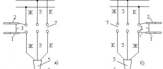
The order of phasing in lines of different voltages is approximately the same. Thus, phasing of a cable line using voltage indicators is performed in the following sequence (see Fig. 1). The serviceability of the voltage indicator is checked, for which the probe of the tube without a neon lamp touches the ground, and the probe of the other tube is brought to the core of the energized cable, and the neon lamp should light up. Then the probes of both tubes touch one live wire. The indicator lamp should not light up. After this, the presence of voltage is checked at the terminals of the electrical installation and cable (see Fig. 1c). This check is carried out in order to exclude an error in the phasing of a line that has an open circuit (for example, due to a faulty fuse). The process of phasing itself consists of touching the probe of one indicator tube to any extreme terminal of the installation, for example, phase C, and the probe of the other tube to alternately touch three terminals from the side of the line being phased (see Fig. 1d). In two cases of contact (C-A 1 and C-B1) the neon lamp lights up, in the third (C-C1) the paw will not light up, which will indicate the same phases. Other phases of the same name are defined similarly.
Measuring current distribution in single-core cables
On the power cable, currents flowing both in the conductors and in the metal sheaths and armor are measured. Measurements are made using current clamps.
Depending on the sheath material, armor and position of the cable in space, the currents in them can reach 100% relative to the core current and greatly affect the heating of the cables. Simultaneously with measuring currents at loads close to the rated load, the temperature of the outer covers of the cables must be measured, from which the temperature of the core can be calculated. This temperature should be measured at the hottest point of the cable line and should not exceed the permissible temperature for a given measurement location. If the current distribution is uneven by more than 10%, when individual cables limit the throughput of the entire group of cables, measures must be taken to equalize the currents across phases.
Test report for power cable line above 1000V
Below is an example of filling out the test report tables:
In the “General Data” table, in the column number of couplings, I suggest recording not only intermediate couplings, but also end couplings. In this case, even on a cable without intermediate couplings, it is necessary to indicate the number 2 in this column. With this filling, this column remains empty only in the case of testing the power cable, for example on a drum, or before laying and installation.
| Beginning of CL | End of CL | Cable type | Length, m | Number of couplings | Note |
| ZRU, cell 1 | TP-2, T-1 | SBG 3x35 | 250 | 2 | — |
In the table “High Voltage Insulation Test”, in the leakage current column, it is necessary to record the current at the beginning of the test (steady-state) and the current at the end of the test before removing the voltage.
| Name | Cable | Note | ||
| L1–(L2+L3+^) | L2–(L1+L3+^) | L3–(L2+L1+^) | ||
| Usp (kV) | 60 | 60 | 60 | |
| Iut. (µA) | 110/100 | 120/100 | 110/80 | start/end |
| Cont. tests | 5 minutes | 5 minutes | 5 minutes |