Where is the voltage indicator used?
The success of the work performed and the health of the worker depend on this device - any repair work cannot be carried out under voltage. Before starting any repair, the technician checks that there is no current in the sections, and only then can he disassemble the device, solder contacts, and so on.
How to carry out test monitoring of the device's serviceability? Just check the pointer on a section of the network that definitely has electric current.
There are special devices that create voltage for the indicator, and then the owner will be able to verify the correctness of the values demonstrated by the voltage indicator.
Indicator for microcircuits (logic probe)
If there is a need to check the performance of a microcircuit, a simple probe with three stable states will help with this. If there is no signal (open circuit), the diodes do not light up. If there is a logical zero on the contact, a voltage of about 0.5 V appears, which opens transistor T1; if there is a logical one (about 2.4 V), transistor T2 opens.
This selectivity is achieved thanks to the different parameters of the transistors used. For KT315B the opening voltage is 0.4-0.5V, for KT203B it is 1V. If necessary, you can replace the transistors with others with similar parameters.
Range of indicators
Where to choose a device for measuring voltage in stores?
- Varieties based on detectable voltage (up to 1 kV and more than 1 kV).
- Differences in the number of poles for indicators up to 1 kV (device with 1 and 2 poles).
Devices for different currents (will determine direct and alternating current).
Varieties in the appearance of the device.
Voltage indicators with one and two poles up to 1 kV
The pole of such a device is by touching the wire. Grounding here takes place with the help of a person by touching the contact. Here we can observe a small current occurring, which leads to the activation of the light bulb.
- You can find such a device in a design similar to a fountain pen (to some it may resemble a screwdriver). The material from which the “fountain pen” is made is not susceptible to electric current. Also in the case there is a resistor and a neon light bulb.
- The device is also equipped with a small spring and a place where it fits comfortably in your hand. There is also a small space that the electrician must touch with his finger when working.
- Such a device will show correct data with alternating current, but if you connect it to elements that contain direct current, the indicator (light bulb) will not light up. It is perfect for household use, for example, for checking the voltage in an outlet or the phase in a light switch.
If you work with a source that produces less than a thousand volts, you can do without additional protection - that is, without gloves. Do not use a separate voltage indicator light source that is independently wired.
Such a light bulb may burst during voltage surges, and the worker will suffer because of this. Single pole indicators are less sensitive and may not even detect low voltage.
The bipolar model has 2 separate parts, which are made of material that does not transmit electricity. Also in his device there is an insulated conductor made of copper. It is enough to touch two elements of the device to find out whether there is voltage in the network or not. Like other voltage indicators, the presence of current will be indicated by the lighting of a neon light bulb.
Types of indicators
The main function that the voltage indicator should perform is checking the integrity of the electrical circuit - this is what determines whether the device plugged into the outlet will work or not. Different devices cope with this task in different ways - a standard screwdriver voltage indicator uses to check the current that is already in the network (passive), and inside a multifunctional voltage tester-probe there is a whole circuit with a separate power supply (active), which allows you to dial even de-energized electrical circuits. All these devices work on a similar principle, but have some differences in the rules of use.
Passive screwdriver indicator
This is a single-pole household phase indicator that performs one single task - to show the presence or absence of voltage at a certain point in the electrical circuit. It is not used by professional electricians due to its extremely limited functionality, but at home among a set of tools “just in case” it can come in handy.
The indisputable advantage of the device is that the presence of voltage is shown by a single-pole indicator after touching any current-carrying contact. A neutral wire is not needed - its role is played by the human body holding a screwdriver in its hands. The presence or absence of a phase is indicated by a neon lamp inside the device - to check the voltage, you need to touch the conductor with the tip of a screwdriver, and touch the contact plate on the handle with your hand.
To protect the user from high voltage, a resistor is installed between the tip and the lamp, but because of this, the indicator does not respond to voltages lower than 50-60 volts.
Active screwdriver indicator
Inside the device body there is a circuit powered by its own power source (battery), so it is a more sensitive voltage detector. Instead of a neon lamp, an LED is used here, which reacts not only to touching the conductor, but also if the tip simply enters the electromagnetic field that exists around any live conductor. This property is successfully used to search for wiring in walls or where it breaks. You need to take the screwdriver by the blade and run it along the wire - if in some place the lamp stops shining, it means that the wiring there (+/- 15 cm) is damaged.
Also, the LED indicator will be activated if you touch the tip with one hand and the contact plate in the handle with the other. This property is widely used for testing wires (determining their integrity). You just need to take one end of the wire in your hand and touch the other with the tip of a screwdriver - if there is no break, then the indicator will light up.
The high sensitivity of the device is also its drawback - since the indicator can show the presence of voltage where it has never been and vice versa - it will not respond to a break in the neutral wire (unless the phase and zero are reversed).
Multi-function active screwdriver indicator
This voltage tester is an improved version of the previous tool - it is distinguished by the presence of a switch with which you can adjust the sensitivity of the device, as well as use it in contact and non-contact mode.
Often, such a multifunctional indicator screwdriver is equipped with a mini liquid crystal display, which shows not only the presence of voltage, but also its voltage. This allows you to determine parasitic pickup currents that are difficult to recognize using a conventional voltage indicator in the circuit.
In addition to the display, such devices are equipped with a buzzer, which allows you to use the device without interference in conditions where the digital indicator is not visible. In fact, the TOP models of electronic indicator screwdrivers are simplified multimeters, but with one tip instead of two probes. Some electronic indicator screwdrivers are even capable of measuring the temperature of the surface the tip of the device touches.
Homemade probe (control)
An electrician’s bag often contains a homemade voltage tester with an ordinary 220-volt light bulb - in professional jargon, called a “tester”. Despite its size, it is often more convenient, although all its advantages are fully revealed when checking three-phase networks.
In essence, this is an ordinary light bulb screwed into a socket, and the wires act as probes that touch the contacts on which the presence of voltage must be checked. Compared to other simple indicator probes, the control does not just show the presence of electric current - by the brightness of its glow you can understand whether the voltage in the circuit is normal.
Additional benefits include the ability to check the presence of all three phases. For example, if there are three wires and two of them are “set” to one phase, then any other voltage indicator at the other end of the wire will simply show that a phase is coming to each wire, and the electric motor will not start. In this case, take two controls connected in series, and use free probes to check the phases with each other - the lights on wires with one phase will not light up. Plus, the control can always be used as additional lighting.
The only disadvantage of the device is that one phase can only be checked if there is a neutral wire nearby, although it is difficult to imagine a situation with its absence.
Universal probe
The most common voltage indicator among professional electrician's tools, combining functionality and ease of use. A universal device that can do everything: determines phase and zero in an alternating current network, plus and minus in direct current, rings the wiring, shows what voltage is in the circuit, has an audio and visual indication.
Not all such devices can find wiring through walls, but the remaining functions are more than enough for the daily work that an electrician faces.
The measurement limits are determined by the quality of insulation and the model of the device - 220-380 or voltage indicators up to 1000 V and above.
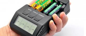
Multimeter - everything at once
An electrical universal tester that combines in one case all the main instruments used by electricians and radio amateurs - a voltmeter, an ammeter and an ohmmeter. In addition, the device can test diodes and transistors, as well as measure the capacitance of capacitors.
The voltage indicator is characterized by high measurement accuracy - depending on the selected mode, it determines the current strength, conductor resistance and other values up to hundredths and thousandths of units. To display measurement results, it is equipped with a liquid crystal indicator.
Indicators with voltage more than 1 kV
This device is equipped with a neon lamp. The connection diagram is serial, with a capacitor base. It is suitable for detecting alternating current, and there is no need to touch the contacts with your fingers.
The voltage here is higher than in other devices, so do not neglect safety rules. Be sure to have gloves in your arsenal (rubber ones are best). It is also necessary to check the instrument every time to avoid breakdowns and inaccurate measurement results.
- How to carry out test monitoring of the device's serviceability? Just check the pointer on a section of the network that definitely has electric current. There are special devices that create voltage for the indicator, and then the owner will be able to verify the correctness of the values demonstrated by the voltage indicator.
- Sometimes work with stress takes place, for example, in a garage. There is a method here that will help you make a test measurement. Start your car or motorcycle and bring your device to the engine. Voltage occurs in the spark plugs, and the gauge will accurately show the result.
Never ground the voltage indicator! This may result in an electric shock and damage the device itself. Grounding is an unnecessary procedure for the device, because it does not affect the accuracy of operation.
LED mains voltage indicator
The circuit of the mains voltage indicator is shown in Fig. 1. During its development, the task was set to make maximum use of available radio components. In this case, failed CFLs can serve as donors of elements [1, 2]. The parts used must, of course, be in good working order. Such an indicator must have threshold elements that are triggered (or switched) at a certain voltage. Such elements in the indicator are DB3 dinistors. They open at a voltage of 28...36 V, which remains almost constant. It should be taken into account that when the polarity is changed, the opening voltage may differ by ±3 V. Relaxation RC generators are assembled on dinistors.
Rice. 1. Circuit voltage indicator
The mains voltage rectifies diode VD1, ripples are smoothed out by capacitor C1. Resistors R2-R7 form a resistive voltage divider, which sets the thresholds for turning on the relaxation generators. The first generator is assembled using elements R8, C4 and VS2. Its switching voltage (in this case 150 V) is set with trimming resistor R4. When di-nistor VS2 opens, capacitor C4 is discharged through it, LED HL1 and resistor R11. In this case, the LED flashes at a frequency of a fraction of a hertz. As the voltage increases, the frequency of flashes increases.
When the mains voltage reaches 190 V, the second generator will start working on elements R9, C3 and VS3. The response voltage is set by trimming resistor R5. This generator operates at a frequency of several tens or hundreds of hertz. Transistor VT1 will open at the same frequency, so capacitor C4 does not have time to charge and the first generator will stop working. As a result, the LED will go out.
When the voltage reaches 240 V, the third generator will start working on elements R10, C2, VS1. The response threshold is set by trimming resistor R6. Since the capacitance of capacitor C2 is significantly less than the capacitance of capacitor C4, the frequency of the third generator will be significantly higher - several hertz. Thus, a voltage interval of 150...190 V is indicated by LED flashes with a significantly lower frequency than at a voltage of more than 240 V. In this way, the indicated voltage intervals can be distinguished.
If this is not necessary, to ensure a “constant” glow of the LED, the capacitance of capacitors C2 and C4 must be reduced to 0.047...0.1 µF, and the capacitance of capacitor C3 - to 10 nF. In this case, the LED flashes occur at a frequency indistinguishable to the eye.
Rice. 2. Drawing of the printed circuit board and placement of elements on it
Most of the elements are mounted on a printed circuit board made of fiberglass foil on one side with a thickness of 1.5...2 mm, a drawing of which is shown in Fig. 2. From the CFL you can use a 1N4007 diode, DB3 dinistors, a transistor of the xx13001 series, capacitors C1 (oxide) and C3 (film). You will need to purchase tuning resistors SP3-19 or suitable imported ones, fixed resistors - C2-23, P1-4, capacitors C2 and C4 - K50-35 or imported ones, as well as an LED of any color, but always super-bright with a permissible current of at least 20 mA. If a voltage of more than 280 V is possible in the network, the rated voltage of capacitor C1 should be more than 400 V.
Rice. 3. Appearance of the mounted board
The appearance of the mounted board is shown in Fig. 3. It is placed in a plastic cylindrical medicine container with a diameter of 30 mm and a length of 60 mm. The pins of the XP1 connector (ShP-4 plugs) are installed in the container lid. Resistor R1 is installed between the connector and the printed circuit board. For the LED, a hole of the appropriate diameter is made in the bottom of the container. The appearance of the device is shown in Fig. 4. You can use another plastic case to place the board, and connect to the network using a cable with a power plug.
Rice. 4. Appearance of the device
The setup comes down to setting the thresholds for the generators to operate with resistors R4-R6, as discussed above. You can shift the generator switching thresholds by selecting resistors R2, R3. Increasing their resistance increases the response thresholds. If you need to increase the thresholds, you need to increase the resistance of resistor R3. To reduce the thresholds, reduce the resistance of resistor R2.
Using the circuit solutions used in this indicator, you can create another indication algorithm.
Literature
1. Nechaev I. From parts of energy-saving fluorescent lamps. - Radio, 2012, No. 6, p. 26-28.
2. Nechaev I. From CFL parts. LED flasher for a New Year's toy. - Radio, 2012, No. 11, p. 36, 37.
Author: I. Nechaev, Moscow
Indicators with a universal device
Sometimes electricians need to “ring” a network, and then they use universal indicators. They have a large capacitor capacity, which acts as a voltage source. If other devices often use neon lamps, here the presence of current will be shown by LEDs.
Advanced users stick out devices with displays where the voltage value is indicated. Most often, universal devices operate on batteries.
Another way to find out about the presence of current is to study the electromagnetic field, and indicators hidden in the rooms cope with this task. When changes occur, they signal with color and sound.
AC voltage indicator 220 V
Let's consider the first, simplest version of a network indicator on an LED. It is used in screwdrivers to find the 220 V phase. To implement it we will need:
- Light-emitting diode;
- resistor;
- diode.
You can choose absolutely any LED (HL). The characteristics of the diode (VD) should be approximately as follows: forward voltage, with a forward current of 10-100 mA - 1-1.1 V. Reverse voltage 30-75 V. Resistor (R) must have a resistance of at least 100 kOhm, but not more than 150 kOhm, otherwise the brightness of the indicator will decrease. Such a device can be made independently in a hinged form, even without the use of a printed circuit board.
The circuit of a primitive current indicator will look similar, only it is necessary to use capacitance.
Rules for using a voltage indicator
Working with tension is a dangerous craft that should only be performed by professionals. Familiarize yourself with the basic rules for working with a pointer.
Perform a test to check whether the instrument readings are correct.
- To do this, use a network that definitely has electric current.
- If the indicator shows the presence of voltage, then it is working properly.
- Do not connect a regular light bulb as a voltage indicator in the device.
- This may result in deformation of the light bulb and subsequent injury to the worker.
Be careful when working with the voltage indicator, follow the above rules.
Double pole indicator
Two-pole devices are more complex and contain two dielectric housings. Each case contains everything that is included in an ordinary indicator screwdriver.
However, some models can also produce sound in addition to a light signal. It is also important to note that both cases are connected to each other by wiring, the length of which is different in each version.
There are models that are non-contact voltage indicators.Using such a device, you can determine not only the phase or the presence of voltage in the network. They make it possible to determine the presence of current between two electrical contacts in a circuit.
The range of devices is very extensive and the main differences between them are in functionality. But all devices of this nature are considered professional electrician tools, since they are the most accurate and convenient even when performing complex work.
- How to fix a laptop that won't charge
- Insulated dielectric screwdrivers up to 1000V - tips on how to choose the best manufacturer
- Dielectric insulated tool for work - which one is better to choose? Review of manufacturers, photos + video
Thus, a two-pole voltage indicator is more suitable for those who are professional electricians.