Galvani Potential
Within a conducting material, the energy of an electron is influenced not only by the average capabilities, but also by the particular thermal and atomic environment in which it is found. When a voltmeter is connected between two different types of metal, it does not measure the difference in electrostatic potential.
The quantity measured by a voltmeter is negative and is usually called the voltage difference. While the net uncorrected electrostatic capability (not measured by a voltmeter) is sometimes called Galvanic. The terms "voltage" and "electric potential" are ambiguous in the sense that in practice they can refer to either in different contexts.
Foreign-made products
Technologies in the construction industry are developing and the construction market has become increasingly supplied with foreign-made terminal blocks. If you compare domestically produced and foreign products, the latter look more perfect, and it is more convenient and easier to work with them.
But if we consider the reliability of the design, then foreign products raise doubts. Still, domestically produced products are more reliable. However, among foreign products there are those products that are worth paying attention to.
Particular attention should be paid to WAGO products. The company's engineers have developed several designs in which an ordinary terminal has turned into a convenient connecting device:
- push wire;
- power cage clamp;
- cage clamp.
The Wago concern supplies the world market with a huge range of terminals and connectors, which are often used when working with electrical wiring. Terminals and clamps are designed to constantly press the contact so that over time the contact does not weaken due to plastic deformation.
Spring terminals from Vago have two main parts: a current-carrying busbar and a pressure spring. Since the terminals are small in size, they easily fit into the mounting boxes of electrical appliances and electrical installations. WAGO develops transparent products that allow the connection to be visually inspected .
Among the company's products there are connectors with a flat spring. This type of product absolutely eliminates the possibility of accidentally disconnecting the conductor from the contact pad.
FOR REFERENCE! The terminal block from the WAGO 222-413 series can connect stranded and solid wires, while maintaining excellent connection quality and ensuring reliable contact with the conductive busbar.
Connector type 1 – Push wire
The essence of this connector is that it is produced using Push wire technology, based on the use of the rigidity characteristics of the conductor. This results in a strong connection.
This type is suitable for single-core wires. Working with the Push wire connector is easy and quick. To do this, a part of the wire (1-1.5 cm) is stripped and pushed inside the terminal. To pull out the conductor, it is pulled out and at the same time rotated around its axis.
There are two types of Push wire connectors:
- For a group of wires;
- For one wire.
Connectors for a group of conductors are designed to work with products of less rigidity, since a different method of mechanical clamping is used. In order to gain access to the wire entry holes, you need to apply force to the push button.
Connector type 2 – Power cage clamp (universal)
This is a universal design used for conductors with a cross section of 6-95 mm. It has the appearance of a double cage, which contains a spring press and a current-carrying busbar. This terminal has a different cross-section and is used for installing lines of various capacities.
DC voltage
In such circuits, the value of the described characteristic remains constant for a long time. A gradual change in the value of this characteristic when connecting consumers (load) to the battery is associated with its discharge - a decrease in the potential difference between the terminals of the power source due to the movement of a larger number of charge carriers from the positive terminal to the negative.
Current and voltage in this case are related by Ohm's law, the formula of which is given below:
I = U/R,
Where:
- I – current strength, A;
- U – potential difference, V;
- R – resistance, Ohm.
Ohm's triangle is a convenient form of the formula of the law of the same name
How to calculate three-phase voltage
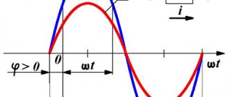
Industrial power transmission uses three symmetrically spaced voltage sinusoids, which are produced by generators.
The three windings of their rotor are spaced 120 degrees apart and rotate in the magnetic field of the stator, alternately crossing its lines of force. Therefore, a displaced electromotive force is induced in them in the same way.
The sinusoids are shifted among themselves by the same angle as shown to the right. Their vector expression on the complex plane is also displayed with an angle of 120°.
In this case, a system of linear and phase voltages is formed, shown in the picture.
A potential difference of 380 volts is formed between all linear wires. At the same time, relative to each of these conductors and zeros, the familiar 220 is present.
Such a system constantly operates in a balanced mode: the currents of single-phase consumers circulate through their closed circuits, constantly adding up in the neutral conductor. The addition is not purely arithmetic, but vector, taking into account the direction of energy flow.
Therefore, when geometrically adding vectors, the current in the zero wire decreases and, as a rule, it is made thinner than the other wires.
Formulas for electric voltage for linear and phase quantities, as well as currents, can be found directly in the picture.
Principle of operation
The simplest alternator consists of the following parts:
- 2 permanent magnets of different polarities.
- Frames made of copper wire.
- Contact rings from which the resulting voltage is removed.
A simple alternator works according to the following principle:
- Permanent magnets create a magnetic field.
- When the copper frame rotates, these fields are intersected by the frame itself.
- When the fields intersect, electricity is generated on the frame.
- If there is no intersection, the voltage disappears.
The frame, performing one complete rotation, crosses the magnetic field twice. Thus, the direction of the EMF changes to the opposite. A change in the direction of the EMF leads to the appearance of a sinusoidal or alternating current.
In such an experiment, not only a change in the direction of the EMF is observed, but also a complete loss of electrical voltage. In order for this effect to disappear, the alternator is equipped with a drive. The drive is used to constantly rotate the generator armature in order to minimize voltage loss and maintain it at a given level. Generators are powered in several ways. This could be an internal combustion engine, transmission rotation from water, steam, oil or gas combustion, or wind energy.
How to find current through resistance and voltage
The current strength is denoted by the Latin or, and it depends on the amount of charge transferred from one pole to the other over a certain period of time, i.e. I = q/t. The current is measured in amperes, and you can find out its value in the circuit using an ammeter.
A man counts the current strength
There are formulas for determining current strength through voltage and resistance. In the first case, the product of current and time is equal to work divided by voltage: I*t = A/U, in the second - according to Ohm’s law, I = U/R. Through power, force will equal P/U.
With a series connection, the current is the same in all parts of the circuit, therefore, equal to the total value in the circuit. Otherwise, the strength of the electric current is equal to the sum of the current strength of all loads.
Thus, there are a huge variety of formulas for finding current, voltage and resistance. They can always be useful for theory, but in practice special devices - an ammeter and a voltmeter - will always help.
Electricity
- Electric current
is the directional (ordered) movement of charged particles.
Electric current in conductors is:
in metals
— directed movement of electrons (conductors of the first kind);
in electrolytes
— directed movement of positive and negative ions (conductors of the second kind);
in plasma
- directional movement of electrons and ions of both signs (conductors of the third kind).
For the direction of electric current
agreed to calculate the direction of movement
positively charged
particles.
The movement of charged particles inside a conductor cannot be observed, but the presence of an electric current can be judged by its actions:
- thermal
- the current-carrying conductor heats up; - magnetic
- a magnetic field appears around a current-carrying conductor; - luminous
- a conductor carrying current can glow; - chemical
- the chemical composition in a conductor carrying current changes (such conductors are called second-class conductors).
For the continued existence of electric current in a closed circuit, the following conditions must be met:
- the presence of free charged particles (current carriers);
- the presence of an electric field, the forces of which, acting on charged particles, cause them to move in an orderly manner;
- the presence of a current source within which external forces move free charges against electrostatic (Coulomb) forces.
The quantitative characteristics of electric current are current strength I
and current density
j
.
- Current strength
is a scalar physical quantity equal to the ratio of the charge Δ
q
passing through the cross section of the conductor over a certain period of time Δ
t
to this interval:
\(~I= \dfrac{\Delta q}{\Delta t}.\)
The SI unit of current is the ampere (A).
If the current strength and its direction do not change over time, then the current is called constant
.
- Current density j
is a vector physical quantity, the modulus of which is equal to the ratio of the current
I
in the conductor to the cross-sectional area
S
of the conductor:
$$~j = \frac {I}{S}.$$
The SI unit of current density is ampere per square meter (A/m2).
*Dependence of current strength on charge speed
Let us consider how the current strength depends on the speed of the ordered movement of free charges.
Let us select a section of the conductor with cross-sectional area S
and length Δ
l
(Fig. 1).
The charge of each particle is q
0. The volume of the conductor, limited by sections
1
and
2
, contains
n∙S
∙Δ
l
particles, where
n
is the concentration of particles. Their total charge is \(~\Delta q = q_0 \cdot n \cdot S \cdot \Delta l\).
Rice. 1
If the average speed of the ordered movement of free charges is \(~\left\langle \upsilon \right\rangle\), then over a period of time \(~\Delta t = \dfrac{\Delta l}{\left\langle \upsilon \right \rangle}\) all particles contained in the volume under consideration will pass through the section 2
.
Therefore, the current strength: \(~I = \dfrac{\Delta q}{\Delta t} = \dfrac{q_0 \cdot n \cdot \left\langle \upsilon \right\rangle \cdot S \cdot \Delta l} {\Delta l} = q_0 \cdot n \cdot \left\langle \upsilon \right\rangle \cdot S. \qquad (1)\)
Thus, the current strength in the conductor depends on the charge carried by one particle, their concentration , the average speed of directional movement of particles and the cross-sectional area of the conductor.
Note that in metals the magnitude of the vector of the average speed of the ordered movement of electrons \(~\left\langle \upsilon \right\rangle\) at the maximum permissible current values is ~ 10-4 m/s, while the average speed of their thermal movement ~ 106 m/s.
As follows from formula (1), the current density is \(~\vec j = q_0 \cdot n \cdot \left\langle \vec \upsilon \right\rangle\).
- The direction of the current density vector \(~\vec j\) coincides with the direction of the speed vector of ordered motion \(~\left\langle \vec \upsilon \right\rangle\) of positively charged particles. The DC current density is constant over the entire cross-section of the conductor.
What is the voltage?
Voltage is directly related to current work, charge and resistance. To measure the voltage directly in an electrical circuit, you need to connect a voltmeter to it. It is connected to the circuit in parallel, unlike an ammeter, which is connected in series. The clamps of the measuring device are attached to those points between which the voltage needs to be calculated. For it to display the value correctly, you need to turn on the circuit. In the diagrams, the voltmeter is indicated by the letter V surrounded by a circle.
Image of a voltmeter and an electrical circuit
Voltage is denoted in Latin and measured in. It is equal to the work that the field does when moving a unit charge. The formula for current voltage is U = A/q, where A is the work done by the current, q is the charge, and U is the voltage itself.
Note! Unlike a magnetic field, where charges are stationary, in an electric field they are in constant motion. Electric field
Electric field
Manufacturing companies
Since terminals are a necessary element of any electronics, such a product is in high demand, and many companies produce it.
The main terminal manufacturing companies include:
- Weidmüller . One of the largest manufacturers of automation systems and industrial connections. Today, terminals from Weidmuller are known in many countries around the world, including Russia. The company is a large international holding company and has representative offices in more than eighty countries around the world.
- Phoenix Contact . The group of companies includes twelve enterprises and has its own production structures. The company is distinguished by the production of high-quality terminals for the high price segment. This manufacturer has offices in approximately thirty countries around the world.
- WAGO Kontakttechnik . One of the largest German manufacturers, offering terminals in many countries around the world. He is the inventor of the Cage Clamp, which has become the reason for its popularity throughout the world. It has its own factories, which are located in different countries of the world, including in Europe. The manufacturer offers high quality products in the premium segment.
There are also other companies producing terminals and terminal blocks, but the three companies presented above are enough to choose the right device. It is wise to give preference to products from well-known manufacturers.
Voltage information
Voltage is the work of an electric current that moves a charge from one point to another. It has a vector direction. Electric current is the movement of charged elementary particles under the influence of an electromagnetic field.
Some novice physicists do not know how voltage is measured.
Knowing this is very important, since the elements of an electrical circuit can be calculated incorrectly. The unit of current is ampere (A) and voltage is volt (V)
In the latter case, a voltmeter is used - a device that measures the voltage or potential difference. It is connected in parallel to the system. For example, you need to measure its value on an incandescent light bulb. To do this, you need to connect in parallel to it, and not in series.
Physical meaning
The physical meaning of voltage or potential difference is the work required to move a point charge of 1 C from one place to another. In this case, only the positive potential is transferred. In this case, an electromotive force (EMF) arises, which is called voltage or potential difference.
To understand the physical meaning, we should consider a simpler example. Let there be a system consisting of a pump, pipes and a tap. The pump is the electric field strength, the pipes are the wires, and the tap is the system resistance. When the first one is turned on, water is pumped. If you open the tap a little, it will flow in a small stream. When it is opened completely, the liquid will flow out more intensely.
Formulas for calculations
All formulas for calculations are based on Ohm's laws. There are only two of them: for a section and for the entire chain. The formulation of the first: the current flowing in the desired area is directly proportional to U and inversely proportional to R. Its mathematical notation has the following form: I=U/R. From the latter we obtain the following relations:
- U=IR.
- R=U/I.
- P=IU=(I2)R=(U2)/R, where P is power.
For a complete circuit, the law is formulated differently: current I is directly proportional to the emf (E) and inversely proportional to the algebraic sum of the external R and internal r resistances. It should be noted that r is the conductivity of the power source. It is written in this form: I=E/(R+r). Physicists have derived the following relationships to help with calculations:
- E=I (R+r).
- R=(E/I)-r.
- r=(E/I)-R.
- Р=ЕI=(E2)/(R+r)=(R+r)I2.
Identities for alternating current
AC voltage is classified into certain types. These include the following:
- Instantaneous or current is a parameter that is measured by instruments (Um).
- Amplitude is a value characterizing the maximum value at a certain point in time. It is calculated by the formula taking into account the angular frequency (w), time (t) and the angle between phases (f), which is measured by an oscilloscope: u (t)=Uмsin (wt+f).
- Root mean square (Uq) is a value calculated by the formula: Uq=0.7073Um).
To calculate, you should have knowledge of inductive Xl, capacitive Xc and resistive R loads. The first is the conductivity of all elements containing inductance (coils, transformers, electric motors). In the second case, all capacitive radio components (varistors and capacitors) are taken into account. Resistive load includes all resistor values.
The total impedance of the circuit (Z) is equal to the sum of all elements, containing active, inductive and capacitive. Experts recommend using the following formulas necessary for calculations:
- Xl=wL.
- Xc=1/wC.
- Z=R+Xc+Xl.
- I=Uм/Z.
- Um=IZ.
- Z=Uм/I.
The fourth formula is Ohm's law for a section of a circuit, which should be applied to alternating currents.
Thus, using the voltage formula, you can calculate not only the basic parameters of electricity for direct and alternating currents, but also its permissible values for humans.
Alternators
Alternating current generators are designed and operate on the principle of a simple experimental alternator. These devices consist of the following elements:
- Rotor. It is a metal core placed on the main shaft of the generator. The rotor may or may not have a winding wire. It all depends on the type of device. The rotor is the moving part of the device. It is driven by a drive mechanism (engine, turbine, blades).
- Stator. The fixed part, which is also equipped with a copper winding. The winding is placed in specially cut grooves and has insulation between the metal casing and the wire itself.
- Slip rings with brushes or commutator. These elements are used to apply constant voltage to the windings to initially excite them. The collector is also used as a rectifier. It prevents directional changes.
This generator works according to the following principle:
- The excitation current is supplied to the stator winding, which is a permanent magnet. Next, a magnetic field is formed.
- The rotating rotor with winding also becomes a permanent magnet. Because of this, an EMF is created between the stator and the rotor.
- During rotation, the magnetic field intersects, resulting in the formation of alternating current.
- Current flows through the switching brush assembly into the connected circuit.
Alternating current generators come in many varieties. They differ in:
- Classifications. Can be synchronous or asynchronous. Synchronous are dependent on the rotation speed and the frequency of the alternating EMF. Such generators are easy to identify visually. Their movable rotor has a winding. Asynchronous ones do not have a winding on the rotor. They do not depend on rotation speed, are more resistant to changes in speed and are not subject to rapid heating during short circuits.
- According to the method of arousal. There are 4 main types: from an external power source; self-exciting; from a more powerful generator that works in conjunction with the main one; from a permanent magnet.
- By number of phases. There are single-, two- and three-phase models. The most common are three-phase types of devices.
- According to the method of connecting the stator winding. There are 2 main schemes - a triangle and a star. The difference between these two schemes is the way they are connected. When a star is used, all ends of the windings are connected at one point. “Triangle” - provides for a serial connection of all ends of the winding.
- By design. Variable type generators can be: with a fixed stator or with a fixed rotor.
- According to the method of energy conversion.
Also, generators may differ in the method of operation. They can be stationary or portable.
Units of measurement in the formula
In the formula for voltage, the SI value is volt. Thus, 1B = 1 joule/coulomb. The Volt is named after the Italian physicist Alessandro Volta, who invented the chemical battery.
This means that in the voltage formula in physics, one coulomb of charge will gain one joule of potential energy when it is moved between two points where the electrical potential difference is one volt. At a voltage of 12, one coulomb of charge will receive 12 joules of potential energy.
A six-volt battery has the potential for one coulomb of charge to produce six joules of potential energy between two locations. A nine-volt battery has the potential for one coulomb of charge to produce nine joules of potential energy.
Physical work of a test charge in an electric field
So, you have turned into a test electric charge
q,
many times smaller than the charge
Q
on the capacitor plates, and have begun your journey between the capacitor plates.
In this case, you will experience the action of Coulomb forces. Let's say that you are a negatively charged particle like an electron, then you will be attracted towards the +Q
-Q
plate . The closer you are to one of the plates, the stronger you will experience its force.
Let's assume that you entered the capacitor from the plate side -Q
and you immediately began to be pushed away from it towards the
+Q
.
You did not resist this influence and decided not to resist nature and move in complete agreement with the attraction. For these purposes, beams and stairs are conveniently located, along which you can freely reach the +Q
by any route.
Since the electric Coulomb force acts on you, you begin to freely pick up speed, as if you were being carried by the wind. As a result, you have covered the distance along the beam from one ladder to another in the direction from point A
to point
B
(
see picture above
).
Stairs are equipotential lines, and accordingly, you have covered the distance from one potential value to another. In our case, you moved from the potential that was larger for you to the one that was smaller. If you were a charge of a different sign, that is, +q
, then the potentials would change their signs and the larger one would become smaller, and the smaller one would become larger.
Mathematically, this means multiplying the potentials by -1
.
A force acted on you and you moved from point A
to point
B
, in other words, you moved from
potential φa
(larger) to
potential φb
(smaller).
It's like floating down a river on a raft, where you don't have to row oars and don't need a motor to propel you. We can say that you have done mechanical work, which is calculated as the product of force and distance. Having made such a movement, you lost some of the potential energy, which turned into kinetic energy (the speed of your movement), and then was probably released in the form of heat during braking. Having made the return journey from point B
to point
A
, you will move against the flow, as it were, you will have to expend energy, row with oars, use a motor, etc. By moving back you will increase your potential energy, because you will move to a point with greater potential and your energy state will increase.
The difference between these two potentials φa
and
φb
and will be the electrical voltage. These are equivalent concepts, but in practical electrical engineering the expression most often used is not potential difference, but voltage. When considering electrical circuits, the expression used is the voltage drop across a section of the circuit, and for sources of electricity, the same potential difference is defined as electromotive force (EMF).
Potential difference Δφ=φ1-φ2
always shows what work
A
can be done by a charge carrier
q
when moving this charge from a point with one potential
φ1
to a point with another potential
φ2
.
When calculating, you must keep in mind that potentials can have either a plus
or a
minus
.
If a charge needs to expend energy for such a movement, and therefore increase its potential, then work A
will have a sign (-), and if the charge carrier moves from a region of high potential to a region of low potential, then energy is released and work
A
will have a sign (+).
Thus, electric voltage is an energy characteristic
of the electric field and represents a potential difference
Δφ
.
This means that it is fundamentally incorrect to say that voltage is potential. Electric voltage is always a potential difference and it is only possible between two points of the electric field. If there is one point in the space of the electric field, then it is appropriate to talk only about the potential of this point, but not about its voltage.
It is necessary to be absolutely clear about the differences between such concepts as: electric field strength E
, potential
φ
, and, of course, potential difference - electrical voltage. Having understood these differences, it will be quite easy to understand what electric current is.
Current source
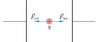
To maintain electric current in the circuit, it is necessary that at its ends (Fig. 2) there is a constant potential difference φ1 – φ2. Let at the initial moment of time φ1 > φ2, then the transfer of positive charge q
from the source terminal “+” to the “–” terminal will lead to a decrease in the potential difference between them.
To maintain a constant potential difference, it is necessary to transfer exactly the same charge from the “–” terminal to the “+” terminal. If in the direction from “+” to “–” positive charges move under the influence of Coulomb forces Fk
, then in the direction from “–” to “+” the movement of charges occurs against the direction of action of Coulomb forces, i.e.
under the influence of another force F
st, which is called an external force.
Rice. 2
- Third-party forces
are any forces acting on electrically charged particles, with the exception of electrostatic (Coulomb) forces.
External forces arise in the current source.
- A current source
is a device capable of maintaining a potential difference between the ends of an electrical circuit and ensuring the orderly movement of electrical charges in an external circuit.
Sources of electric current may vary in design, but in any of them work is done to separate positively and negatively charged particles. The separation of charges occurs under the influence of external forces. We list the most common current sources:
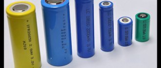
- galvanic cells
(batteries) (Fig. 3, a) and
accumulators
- third-party forces use the energy of chemical reactions; - generators
(dynamos) - third-party forces use the mechanical energy of falling water, wind, steam, etc.; - photocells
(solar batteries) (Fig. 3, b) - external forces use the energy of electromagnetic radiation (light).
- A
- b
Rice.
3 The source of electric current has two poles (two terminals) to which the ends of the wires are connected.
The conductor connecting the terminals of the source from the outside is called the external section of the circuit
.
The resistance of this source is denoted by R
and is called
external resistance
.
Inside the source itself, charges move along the internal section of the circuit
.
The source resistance is denoted by r
and is called
internal resistance
.
The sum of external and internal resistances ( R + r
) is called
the total resistance of the circuit
.
On electrical diagrams, the current source is designated as shown in Fig. 4. The positive pole (terminal) of the source is conventionally represented by a longer line than the negative one.
Rice. 4
Any current source is characterized by electromotive force - EMF.
- EMF (Electromotive force) ε of a current source is a physical scalar quantity that is numerically equal to the work of external forces Ast
to move a single positive charge inside the current source:
\(~\varepsilon = \dfrac{A_{st}}{q} .\)
The SI unit of electromotive force is the volt (V).
EMF is an energy characteristic of a current source.
- The term “ electric motor force
” was introduced by Ampere in 1822. The abbreviation EMF is usually read without decoding.
see also
All about chemical current sources
How the law works in real life
Using the power calculation formula and Ohm's law together, you can make calculations without knowing one of the quantities. The simplest example is that for an incandescent lamp only its power and voltage are known. Using the above formulas, you can easily determine the parameters of the filament and the current through it.
Incandescent lamp
Current formula through power:
I=P/U;
Resistance:
R=U/I.
The same result can be found from the power without resorting to intermediate calculations:
R=U2/P.
Similarly, you can calculate any quantity knowing only two of them. To simplify transformations, there is a mnemonic display of formulas that allows you to find any quantities.
Rule for remembering calculations
Looking carefully at the formulas, you can see that if you reduce the voltage on the lamp by half, the expected power will not decrease by the same factor by half, but by four, according to the formula:
P=U2/R.
This is a fairly common mistake among people who are far from electrical engineering, who incorrectly correlate power and voltage, as well as their effect on other parameters.
By the way. The current found through resistance and voltage is valid for both direct and alternating current, as long as it does not use elements such as a capacitor or inductance.
You can make calculations easier by using an online calculator.
Concept of potential
In order for electrons to pass through a circuit, energy is needed that can set them in motion along an electrical circuit. For example, in the case of static electricity, it is the force produced by an imbalance of electrical charge in objects.
A school experiment with rubbing an ebonite stick on wool illustrates the creation of an excess of electrons in ebonite (negative charge) and a deficiency of electrons in wool (positive charge) when mechanical energy is expended on rubbing.
This is the electric current in the circuit, and the degree of electrification of bodies is a quantity called potential. To simplify the understanding of what is called voltage, we can consider this value as the potential difference between objects.
Classification and types of units
All electric generators can be classified according to operating criteria and the type of fuel from which electricity is generated. All generators are divided into single-phase (voltage output 220 Volts, frequency 50 Hz) and three-phase (380 Volts with a frequency of 50 Hz), as well as according to the operating principle and type of fuel that is converted into electricity. Generators can also be used in various fields, which determines their technical characteristics.
According to the operating principle
There are asynchronous and synchronous alternating current generators.
Asynchronous
Asynchronous electric generators do not have an exact dependence of the EMF on the rotor speed, but a term such as “slip S” works here. It makes that difference. The amount of slip is calculated, so there is still some influence of the generator elements in the electromechanical process of the asynchronous motor.
Synchronous
Such a generator has a physical dependence on the rotational movement of the rotor to the generated frequency of electricity. In such a device, the rotor is an electromagnet consisting of cores, windings and poles. The stator are coils that are connected according to the star principle and have a common point - zero. It is in them that electric current is generated. The rotor is driven by an extraneous force of moving elements (turbines), which move synchronously. The excitation of such an alternating current generator can be either contact or non-contact.
By engine fuel type
With the advent of generators, distance from the power grid no longer becomes an obstacle to using electrical appliances.
Example with ordinary water
This pressure potential is equivalent to voltage. The more water in the tank, the stronger the impact. The more powerful the charge stored in the battery, the higher the voltage.
When you open the hose, a stream of water flows. The pressure in the reservoir determines how quickly it drains. Electrical current is measured in amperes. The more volts, the stronger the A current. This means that the stronger the water pressure, the faster it will flow out of the tank.
However, current also depends on resistance. In the case of a hose, this is its width. A wide pipe allows more water to pass through in less time, while a narrow pipe resists the flow of liquid. With electric current there can also be resistance, measured in ohms.
Ohm's law
The electrical circuit consists of separate sections - homogeneous and inhomogeneous. Sections of the circuit in which there is no action of external forces, i.e. sections without current sources, are called homogeneous. Sections of the circuit where there are current sources are called inhomogeneous.
The formula for Ohm's law for a homogeneous section of a chain looks like this:
$ I = {U \over R} $ (1).
The full formulation of Ohm's law is as follows: the current strength I for a conductor in a homogeneous section of the circuit is directly proportional to the voltage U in this section and inversely proportional to the resistance of the conductor R.
For a non-uniform section of a circuit containing a current source with electromotive force Eems, Ohm’s law is written as follows:
$ I = {E_{emf} \over R + r} $ (2),
where: R is the circuit resistance, r is the resistance of the current source. Equation (2) is called Ohm's law for a complete circuit: the current in a complete circuit is equal to the source emf divided by the sum of the resistances of the homogeneous and inhomogeneous sections of the circuit.
The essence of the phenomenon
Voltage is the electrical driving force that is designed to push free types of electrons from one atom to another in a certain direction. A mandatory requirement for the flow of charges is the presence of a circuit with a closed loop, which creates the conditions for them to move. If there is a break in the electrical circuit, then the process of directional movement of particles stops.
Note! It is worth noting that the unit of voltage in an electrical circuit depends on the material of the conductor, how the load is connected, and what the temperature is. What it is
What it is
Characteristic values and standards
| An object | Voltage type | Value (at consumer input) | Value (at source output) |
| Electrocardiogram | Pulse | 1-2 mV | — |
| TV antenna | Variable high frequency | 1—100 mV | — |
| Galvanic zinc cell type AA (“finger”) | Permanent | 1.5 V | — |
| Lithium Galvanic Cell | Permanent | 3—3.5 V (finger-type element, using the example of Varta Professional Lithium, AA) | — |
| Logic signals of computer components | Pulse | 3.5 V; 5 V | — |
| Battery type 6F22 (“Krona”) | Permanent | 9 V | — |
| Power supply for computer components | Permanent | 5 V, 12 V | — |
| Electrical equipment of cars | Permanent | 12/24 V | — |
| Power supply for laptop and LCD monitors | Permanent | 19 V | — |
| "Safe" reduced voltage network for operation in hazardous environments | Variable | 36-42 V | — |
| Voltage of the most stable burning of Yablochkov candles | Permanent | 55 V | — |
| Voltage in the telephone line (with the handset on-hook) | Permanent | 60 V | — |
| Japan power grid voltage | AC three-phase | 100/172 V | — |
| US Home Electrical Voltage | AC three-phase | 120 V / 240 V (split phase) | — |
| Voltage in household electrical networks in Russia | AC three-phase | 220/380 V | 230/400 V |
| Electric ramp discharge | Permanent | up to 200-250 V | — |
| Tram and trolleybus contact network | Permanent | 550 V | 600 V |
| Electric eel discharge | Permanent | up to 650 V | — |
| Metro contact network | Permanent | 750 V | 825 V |
| Contact network of an electrified railway (Russia, direct current) | Permanent | 3 kV | 3.3 kV |
| Low power overhead power distribution line | AC three-phase | 6—20 kV | 6.6—22 kV |
| Power station generators, powerful electric motors | AC three-phase | 10—35 kV | — |
| At the anode of the kinescope | Permanent | 7—30 kV | — |
| Static electricity | Permanent | 1—100 kV | — |
| On a car spark plug | Pulse | 10-25 kV | — |
| Contact network of the electrified railway (Russia, alternating current) | Variable | 25 kV | 27.5 kV |
| Air breakdown at a distance of 1 cm | 10-20 kV | — | |
| Ruhmkorff coil | Pulse | up to 50 kV | — |
| Breakdown of a 1 cm thick layer of transformer oil | 100-200 kV | — | |
| High power overhead power line | AC three-phase | 35 kV, 110 kV, 220 kV, 330 kV | 38 kV, 120 kV, 240 kV, 360 kV |
| Electrophore machine | Permanent | 50—500 kV | — |
| Ultra-high voltage overhead power line (inter-system) | AC three-phase | 500 kV, 750 kV, 1150 kV | 545 kV, 800 kV, 1250 kV |
| Tesla Transformer | Pulse high frequency | up to several MV | — |
| Van de Graaff generator | Permanent | up to 7 MV | — |
| thunder cloud | Permanent | From 2 to 10 GV | — |
What is EMF
What is EMF, do you think? I'll tell you now!
Electromotive force (EMF) is also measured in Volts, like voltage.
Let's take a device that measures volts (voltmeter), a battery and take a measurement.
The device shows 1.5 Volts and this is not voltage, but electromotive force (EMF).
Now let’s connect the light bulbs to the battery.
Measuring voltage in various parts of an electrical circuit.
We noticed that on one light bulb the voltage (not EMF) is 1 Volt, and on the other 0.3 Volts
The voltage on the light bulbs depends on their power. Power is measured in Watts.
Power=Voltage*Current (P=U*I)
The higher the power of the light bulb, the higher the voltage will be on it.
If our battery is 1.5 volts = 1 volt +0.3 volts = 1.3 volts, where did the 0.2 volts go? The battery also has its own internal resistance, so that’s where they went.
Electronics for everyone
Another post from the basics series. I noticed that many people are completely unaware of the concept of voltage drop, potential difference and types of power sources. Therefore, I will write down an educational program on this topic. From the very beginning. Then I’ll throw it at the beginning of the “Beginners” section. It will serve as a replacement for a series of articles on sewer electronics. Because that series was written for “Hacker” and was not particularly detailed due to restrictions on the size of the page.
The beginning of time. Zero.
So, I'll start from the beginning.
From the bottom. That is, from the ground. Zero potential points. This point is completely arbitrary. It’s just so convenient for us that we took it for zero. We have to start somewhere. In unipolar nutrition, this is usually a minus of nutrition. In bipolar there is something in the middle, but it depends on the design. Energy source
What is a source of electrical energy anyway? This is just a “charge pump” that pumps electrons (or ions) through chemical, electrostatic, ferroelectric, electromagnetic, thermal, and any energy. It doesn't matter. The only point is that it distorts the neutrally uniform distribution of charges, pulling positive ones in one direction and negative ones in the other. Like a pump, raising water to a height, due to the energy of a crowd of dirty niggas, in the sweat of their brows rotating its flywheel, increases the potential energy of the water raised to a height.
And if we take one end of our conductor pipe as zero, then there will be some kind of potential at the other. Which? And this depends on the strength of the energy source, because the charges resist, they want to go back to the zero state. System with minimal energy. And also on the characteristics of the force itself. For example, the chemical one in salt batteries does not produce a voltage greater than 1.5 volts. These are the properties of the electrolyte and electrodes (I have already forgotten the chemistry, but something is connected with the electrochemical series). Moreover, we can form energy sources in a chain. And then it turns out that the output of the first one will become a point of zero potential for the second one, the same, and it will be able to pump up the same amount from above. And relative to the general zero it will be twice as much.
It’s as if we connected two pumps in series, one gives us a pressure of 1 atmosphere, and the second one gives us 1 atmosphere relative to it, and together they give as many as two points.
At my last job they made bench multimeters. They were made from ordinary DT-838 by screwing them onto the panel. They did it en masse, in the hundreds. And all of them are supplied from the factory with a KRONA type battery, which turned out to be unnecessary here. The battery was useless, but it provided its 9 volts. And there was a whole box of these batteries from the TV, in bulk. And the Crown is cool because it can connect with its connector to another Crown. Well, I don’t care, let’s connect them in series, laying them out on the floor. I don’t remember how many of them I connected. Then I became stupidly scared, because... I ran out of space in length, and joining them in two layers was awkward - since the ends were close. And as a result, I got a source with a voltage of almost a kilovolt and capable of delivering a current of a couple of amperes within a few minutes. If I had shortened it on myself, I would have been left with nothing but shoes. I had to disassemble the infernal machine.
Closed circuit
Well, we have sources of energy, everyone increases their potential according to their own stupidity. At the top of this chain we will have their total potential. A wild number of uncompensated charges rushing towards zero. They can be compared to compressed air.
They cannot break back - the source of energy does not provide it. There is nowhere to go forward. There is not enough energy to break through the air. So they hang in this state. Like a battery not connected anywhere - the output is bare potential and no movement. There is voltage, but no current. All that remains is to give them a way. Let's close the circuit. In short, no payload.
And the current will rush along a short path, and then back up at the expense of the energy source, and so on. The voltage at the top will immediately drop to zero. But since there is no resistance, then with what speed will he do it? An ideal pump, with infinite power, will accelerate our current to infinity.
But what really comes into play is the pump's performance. Those. the pump physically, due to its design, cannot pump us more than a certain volume (say, a limited cylinder size), and the battery has a limited area of the electrodes, the generator has winding resistance. It turns out that there is still resistance in the circuit, this is the source resistance. And you can't jump higher than him. Same with a real voltage source. He also always has internal resistance. And the lower it is, the more powerful the source, the more current it can deliver.
However, no one bothers you to take and connect two source pumps in parallel. And it turns out that with the same pressure (voltage) they generate twice as much current. The truth here is that we must take into account that it is impossible to put two sources with different voltages in parallel - then the weaker one will be pushed through by the stronger one and serve as a consumer. Of course, if there is no external load that would reduce the voltage to a weak level.
The same applies to sequential switching. If we plug into a series connection a source with a higher internal resistance than all the others, then it will clog the entire circuit and become a burden, preventing it from developing the maximum current.
Now let's think about batteries. When a battery is new, it has low internal resistance, but the more electrolyte reacts, the greater the internal resistance becomes. And it turns out that it produces voltage and the multimeter shows a seemingly clear one and a half volts, but as soon as you demand a large current from it, it instantly blows away - the increased resistance does not allow it to output it and the voltage drops.
And now a little more specifics. Ohm's law for a complete circuit.
There is simply Ohm's law: voltage = current * resistance
U = I * R
This is a special case of Ohm's law for an individual circuit element. But there is also Ohm's law for the complete circuit, taking into account the source.
So, in our chain we have:
Our ideal pump is a source of electromotive force (EMF) - E
. It has infinite power and zero internal resistance. But so that life doesn’t seem like honey, let’s also add internal resistance. To get the real source. Re And there are also loads R1 and R2 connected in series.
The current (I) in a series unbranched circuit is the same everywhere. And it is equal to the value of the EMF divided by the sum of ALL resistances, including internal ones. And this is what comes out of it:
E = I*Re+I*R1+I*R2
Because I*R=U let’s rewrite everything differently:
E = I*Re + U1 + U2
It turns out that the electromotive force of our source is distributed, depending on the magnitude of the load, throughout the entire circuit. The greater the load, the more energy must be applied to overcome it. Those. in our battery, if our E is a constant and does not change (let me remind you that it depends only on the chemistry of the process and the selection of battery materials - i.e. this is a design feature of the battery), then with an increase in Re, in order to maintain equality, we have to reduce current. And if so, then U1 and U2 fall, i.e. voltage at the consumer. You can also notice that for serial consumers, the voltage on each of them depends on its R. And where the resistance is greater, there will be a greater voltage.
What happens when we poke a voltmeter into our dead battery? And the voltmeter has HUGE resistance. And in comparison with it, the internal resistance of the source does not even shine.
Re <<<< Rvoltmeter
And the current is equally small (fractions of a milliampere) for all consumers. So in the equation:
E = I*Re + I*Rvoltmeter
On the numbers:
E=1.5 Re=10 Ohm Rvoltmeter = 10,000,000 Ohm I = 1.5/10,000,010 = 1.499E-7 I*Re = 0.00000015 * 10 = 1.499E-6 I*Rvoltmeter = 1.499E-7 * 10,000,000 = 1.499
1.5 = 1.499E-6 + 1.499
The lion's share of the voltage will land where the resistance is greater - on the voltmeter. And the voltmeter will show practically the value of E, but this will only work at low currents. As the load resistance decreases and the current increases, the I*Re part will become heavier and heavier until it drags the entire voltage onto itself. Then the voltage at the load will drop almost to zero - the battery is simply not able to provide enough current to maintain the voltage. Or, if it is not a battery, but some other source, the source does not pull the load. And if the internal resistance of the battery has increased due to long-term operation of the load, then in this case the battery is dead.
Voltage source. Stabilization
But there are such cunning circuits where the internal resistance of the source can be changed within wide limits. And there is a tracking system that regulates it so that the load has a strictly defined voltage. Of course, as long as the currents do not go beyond the agreed limits, and then failure is inevitable. Moreover, if the load resistance, for example, decreases, then the source resistance will also decrease in order to be able to pass more current through the load and equalize the voltage across the load.
If we take an ideal voltage source - essentially a naked EMF source with zero resistance, then when the load drops to zero it will give an infinite current. The simplest example of a voltage source is a capacitor at the moment of discharge. An ideal capacitor has zero internal resistance, so when it is discharged, it produces an infinitely large current over an infinitesimal period of time.
Potential
Based on the name of the quantity, this is the potential energy of the electric field at a specific point. But in order to measure it, you need to set a starting point, a reference system - the point of zero potential. She could be anywhere. It depends only on our goals at the current moment. But usually the case or minus of the power supply is taken as zero. This will be our point of zero potential - the Earth.
Let's take and add this point to our chain, like this.
So we have a chain. The parameters are:
E = 5V R = 1 Ohm - all resistors, for simplicity. I = 1 A
Now let's find the potential at all points. It is traditionally designated by the letter phi. The rule here is simple:
- 0. Select the zero point.
- 1. Select the direction of the traversal.
- 2. Select the direction of the current in the circuit. Completely arbitrary, if you make a mistake with the direction, then a number of quantities will have a negative sign, but the equation will still converge. However, it is better to choose the current based on a logical assumption of how it should flow for a given direction of the source - there will be fewer minuses.
- 2. If the source is on our path, then it increases the potential by the amount of its emf.
- 3. If there is a load along the way. Then if the current coincides with the selected bypass direction, then we reduce the potential by I*Rн. If the current through the load goes opposite to our bypass, then we increase the potential by I*Rн.
And let's return to our outline:
- 0. The zero point is set.
- 1. Let the circuit traverse clockwise.
- 2. Current is clockwise.
- 3. We pass the EMF source. The potential at point B immediately jumps by its value. This is the maximum voltage. But it’s somewhere deep in the battery; we can’t measure it except mathematically. Therefore, we go through internal resistance. We follow the current, so our potential decreases by I*Re. At Point B we got the real potential at the terminal of our battery. Let's go further, next we have a resistor. There, the current flows around the bypass, which means the potential decreases by another I*R1. The rest is similar. As a result, when we make a circle, the potential on each resistor will drop until it reaches zero upon returning to the starting point of the circle.
If we go around in the opposite direction, we will get the same thing, only the potential will increase until we reach E and, having passed it in the opposite direction, we will not subtract the EMF, reaching zero again.
But we received potential relative to zero. And if we take the potential difference between points G and E? And we will get the voltage between these two points. If you poke a voltmeter there, it will show exactly this voltage. Those. Voltage is a potential difference. And the voltage drop between points is the amount by which the potential changes when moving from one point in the circuit to another.
And most importantly, you need to very clearly understand the fact that the main thing in the circuit is the potential difference. There is a potential difference - there is a current, charges flow and tend to reduce this difference to zero. No - there will be no current, because In this case, the charges will not want to run somewhere and level something somewhere, because The energy of the system in this case is minimal.
There may not be any current if the circuit is not closed, but there is more than enough potential. For example, there is a piece of wire lying around, not connected anywhere. At the ends the difference is zero - all charges are evenly distributed. An electromagnetic wave went past the wire, arrived from somewhere outside, thereby serving as a source of energy and scattering charges at different ends of the wire. A potential difference appeared at the ends.
Thus, even in a leg of the microcontroller that is not connected anywhere, if it hangs in the high input impedance mode (HiZ - that is, it is practically not connected anywhere and the circuit is open), large potentials can be induced from the air, from random interference, sufficient for chaotic switching the input from 0 to 1 and back. And if you attach a long wire to your leg, then such a potential can build up on it that the controller will burn out. Therefore, long lines are usually made in the form of a current loop, with low resistance, so that overvoltages are not induced on them. And the presence or absence of a signal is detected by the presence or absence of a current of the required magnitude.
This concept of potential and the dependence of current on it must be understood thoroughly, at the level of the spinal cord. Because then further operation will be mainly potentials relative to a common point.
The concept of voltage drop is actively used when calculating nonlinear elements such as diodes.
Calculation of a resistor for an LED
So, we have an LED. Somewhat abstract. And according to the datasheet, the voltage drop is 2.5 volts. And the permissible current is 10mA. There is also a battery that provides 5 volts and has an internal resistance of 1 ohm.
What does LED voltage drop mean? And the fact that between its terminals the voltage can be no higher than 2.5 volts. Those. If you plug it into a battery of at least 100 volts, there should still be 2.5 volts. This is achieved due to the fact that the resistance of the diode is lower, the greater the voltage applied to it. Where to put the remaining 97.5 volts? And they will have to be landed on the internal resistance of the source. What if it's not enough? Don't care! You will have to pump in a large current, so large that the ill-fated 97.5 volts drops into the internal resistance of the source. But the current there will go into hundreds of amperes. And the LED from such currents will emit a plasma flash and give you a short circuit with an explosion.
Of course, with a real LED, everything is not so scary and its resistance cannot fall indefinitely, and the voltage drop is not constant and changes, but when these deviations are significant, the current will be beyond the permissible limit. So you can safely take the voltage drop across the LED as a constant.
So, let's get back to our sheep.
There is a source, there is a diode. Here's the diagram.
E=I*Re+Vled 5=I*1 + 2.5
By plugging our five-volt source into our 2.5-volt diode, we get a voltage drop across the diode of 2.5 volts. And the same amount should land on the internal resistance of the source. The current will be 2.5A, which is a lot, two orders of magnitude higher than allowed. This means we need to add another resistor so that it relieves some of the voltage and provides a current of 10 mA.
E=I*Re + I*R + 2.5
It’s clear, because I = 0.01 then calculating R is not difficult. R = 249 Ohm. The closest of the E24 series is 240 Ohms.
We select the parameters of the diode from its datasheet, the current-limiting resistance, but where can we get the internal resistance of the source? But usually it is neglected, considering it equal to zero. One fig, its resistance is orders of magnitude less than the resistance of the limiting resistor.
Current source
Antipode of the voltage source. If a voltage source produces a voltage and can develop an infinite current, just to hold this voltage.
Then the current source produces a current and can produce an infinite voltage, just to push through this current. It has infinite internal resistance, so its output voltage (I*Rin) tends to infinity. A real current source has an internal resistance and it is located in parallel. Those. if the current is not forced through the load, then it flows through the internal resistance, preventing a surge in voltage until the bitter end. And the higher the internal resistance of the current source, the greater the voltage drop across it, and therefore the greater the voltage across the load. Thus, according to Ohm's law, more current will be pushed through the load.
The source of current in nature is an inductor at the moment the circuit breaks. That's why it sparks like that, because... pumps up wild tension, trying to make way for the current and keep it at the same level.
Application of Ohm's law in practice
In practice, it is often necessary to determine not the current strength I
, and the resistance
value
R.
you
can calculate the resistance value R
, knowing the flowing current
I
and the voltage value
U.
| Online calculator for determining the resistance value |
| Voltage, V: |
| Current value, A: |
The resistance value may need to be calculated, for example, when making a load block to test a computer power supply. There is usually a label on the computer power supply case that lists the maximum load current for each voltage. It is enough to enter the given voltage values and maximum load current into the fields of the calculator and as a result of the calculation we obtain the value of the load resistance for a given voltage. For example, for a voltage of +5 V at a maximum current of 20 A, the load resistance will be 0.25 Ohm.
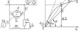
Synchronous electric generator
A synchronous electric generator is a synchronous machine operating in generator mode in which the rotation frequency of the stator magnetic field is equal to the rotor rotation frequency. A rotor with magnetic poles creates a rotating magnetic field, which, crossing the stator winding, induces an emf in it. In a synchronous generator, the rotor is made in the form of a permanent magnet or electromagnet.
The number of rotor poles can be two, four, etc., but a multiple of two. In household power plants, as a rule, a rotor with two poles is used, which determines the rotation speed of the power plant engine of 3000 rpm. The rotor, when starting the power plant, creates a weak magnetic field, but with increasing speed, the EMF in the field winding also increases. The voltage from this winding is supplied to the rotor through an automatic regulation unit (AVR), controlling the output voltage by changing the magnetic field. For example, a connected inductive load demagnetizes the generator and reduces the voltage, and when a capacitive load is connected, the generator is biased and the voltage increases. This is called the "anchor reaction".
To ensure stability of the output voltage, it is necessary to change the magnetic field of the rotor by regulating the current in its winding, which is provided by the AVR unit. The advantage of such generators is the high stability of the output voltage, but the disadvantage is the possibility of current overload, since if the load is too high, the regulator can excessively increase the current in the rotor winding. Another disadvantage of a synchronous generator is the presence of a brush assembly, which sooner or later will have to be serviced. Thanks to this adjustment method, regardless of changes in load current and power plant engine speed, the stability of the generator output voltage remains very high, approximately ±1%.
How to find load resistance
Load resistance is designated by the Latin letters Rn or Rн. In essence, this is the same resistance of the circuit section and is also calculated using the formulas of Ohm’s law. The load is indicated by symbols, which are depicted on the electrical diagram as crosses in a circle - a light bulb; that is, a motor, a lamp, a specific device, etc.
Each load has its own resistance. For example, if one light bulb is connected to the network, then the load resistance is an indicator of this only device in the circuit. If several loads are connected to the circuit, then the resistance is calculated in total for each of them.
The load resistance is calculated in accordance with Ohm's law, that is, Rn = U/I. If several loads are connected to the network, then it will be calculated as follows: first, the resistance of each individual “light bulb” is found. Next, Rn is calculated depending on the type of connection in the circuit: serial or parallel. In parallel, 1/R = 1/R1 + 1/R2 + 1/Rn, where n is the number of connected devices. If the connection is serial, the total R is equal to the sum of all R of the circuit.
Serial/parallel connections
What electrical connections are there?
Connections using terminal blocks can be divided into 2 types:
- Electrical;
- Electrical.
They differ slightly, but there is still a difference. Terminals vary in current load, and this factor should be taken into account when selecting products for installation, repair and other actions.
FOR REFERENCE! Electricians constantly use terminal blocks in their work. Without these components, high-quality work cannot be carried out.
When the question arises about which terminals to purchase, it is best to start with the products offered by a domestic manufacturer. Such products are considered reliable, time-tested and have a good service life.
Terminals come in the following types:
- knife;
- ring;
- coupling;
- pin.
Connections in electrical circuits can be made using different methods, and the use of “clamps” is one of the methods. This option is quite simple and convenient to work with. In addition, it does not require large financial costs, because welding or soldering connections will cost much more.
The advent of terminals has greatly simplified the work of electricians, and the quality of connections has greatly increased . Thanks to the terminals, you can quickly create connections that will be resistant to stress, and they are also protected from dust and water ingress.
The terminal presses the conductive core to the contact pad, which eliminates damage and weakening of the contact. Terminal blocks can be used not only to create linear connections, but also to connect lighting devices and power supplies.
For novice electricians and for those who connect wires on their own, the use of terminals is necessary. With their help, in case of an error, you can connect several times.
To connect using terminal blocks, no special devices (soldering iron, welding machine) are required . Work with these products is done by hand, while maintaining high accuracy and speed of work. Using a terminal block, you can connect several lines and combine the wires into groups so that the electrical wiring can be used rationally.