General classification
The concept itself implies a set of symbols that are intended to identify any structural elements or parts.
In accordance with the rules and requirements of GOST 2.701-84, several types are distinguished, differing both in the scope of application and in the type of symbols installed. The breakdown by type is shown in the table below:
Table: varieties diagram
| № | Scheme type | Letter designation |
| 1 | Electrical | E |
| 2 | Hydraulic | G |
| 3 | Pneumatic | P |
| 4 | Gas (except pneumatic) | X |
| 5 | Kinematic | TO |
| 6 | Vacuum | IN |
| 7 | Optical | L |
| 8 | Energy | R |
| 9 | Divisions | E |
| 10 | Combined | WITH |
Thus, for the same device or object, if necessary, several diagrams can be developed at once, explaining the principle of connection, operation or implementation of functions. For electrical equipment, circuits are divided into several types:
- Fundamental or complete – indicated by the number 3;
- Structural – indicated by the number 1;
- Functional - indicated by the number 2;
- General – indicated by the number 6;
- Installation or connection diagrams - indicated by the number 4;
- Connections – indicated by the number 5;
- Locations and combined are designated by numbers 7 and 0, respectively.
When drawing up a specific diagram, as a rule, alphanumeric designations are used, for example, for an electrical functional marking it will look like E2, for a gas structural one X1, etc.
The principles of graphic designation of any elements on diagrams are determined by industry and state standards. They also establish requirements for the location of components, their sizes, and the application of codes, names or markings.
Definition and purpose of each electrical circuit
Each type of electrical circuit is implemented in the form of a drawing or graphic image, made manually or using printed devices. The main differences are due to the description of certain functions, indication of the sequence, principle of operation, or connection to something.
The principle of constructing circuits is regulated by the ESKD standard, which is implemented by a number of regulatory documents, among which GOST 2.702-2011, as well as GOST 2.708-81, are considered quite important.
They install:
- image requirements;
- principles of component arrangement;
- preparation of drawings;
- application of designations and technical characteristics.
Next, we will consider in detail the features of each type of electrical circuit.
Fundamental (full)
A schematic diagram is intended to explain the principle of operation of a particular device. Most often it is used for various distribution devices in power circuits, any devices, etc.
Circuit diagram example
Schematic diagrams must indicate the operating electrical components and the connections between them, power contacts and electrical components connecting radio components. In turn, such electrical circuits are divided into two subtypes: single-line and complete.
Single-line circuits are also called primary circuits; they usually indicate the power part of the equipment or electrical installation. On the other hand, a single line diagram is widely used to indicate three-phase circuits, where all equipment on three phases has an identical arrangement and connection. Due to this, in the single-line version, only one phase is demonstrated with some deviations in places where the equipment in different phases is different.
In addition to power circuits, there are also low-current circuits for powering protections, measuring equipment and various electronic devices. Such secondary circuit diagrams are called complete, as they show a complete picture of the entire equipment, even highlighting the state of some contacts and parts of the equipment. Alas, due to the complexity of modern equipment, not all devices can be depicted on one sheet, so complete ones can be elemental and expanded.
Full scheme
Structural
Block diagrams provide a general image of a device, all components or individual units of which are made in the form of blocks indicating equipment, and connections between blocks can indicate certain operations connecting individual blocks with each other.
Structural scheme
This type of graphic image is intended to give a general idea of the device and principle of operation, therefore they are often marked with arrows, explanatory inscriptions and other symbols that simplify understanding of the process or explain the operation of the device. To work with such an image, you do not need to have an electrical engineering education, since its designations will be clear even to a person who is not experienced in electricity.
Functional
A functional diagram is a more detailed version of a structural diagram; on it, all elements are also depicted as separate blocks. The main difference is that each block already has an individual form of designation in accordance with its functional purpose. It is also possible to highlight different types of connections between parts, combine parts into blocks, etc.
Functional diagram
General
The general diagram is intended to depict the locations of electrical devices on the ground or within an electrical installation. Determines the main types of electrical connections of these devices, places of their implementation, etc. This type is mandatory when developing various design documents at the design stage. But in addition to the general one, the design documentation includes two more equally important diagrams - connections and connections.
General scheme
Connection diagram (installation)
The connection diagram is used to graphically depict electrical equipment connection points. It indicates a specific connection to parts of buildings, distribution systems, in relation to which the installation of electrical equipment should be carried out, due to which this type of diagram is also called installation diagram.
Most often, wiring diagrams are used to indicate the layout of electrical circuits in a building; they are widely used during repairs to indicate places for laying wiring, installing junction boxes and connecting points to devices and device contacts.
Wiring diagram
The figure above shows an example of a wiring diagram; as you can see, each option can have its own symbols, indicated separately. There are links to each specific room and planned electrical equipment, lighting fixtures, etc. In the future, it is used not only for installation work, but can also be used during operation.
Connections
A wiring diagram is used to indicate the principles of connecting various electrical or electronic components into a single system. Sometimes the units are assumed to be geographically separated, in other situations they may be located within the same switchgear, busbar or rack. An example of this is shown in the figure below:
Connection diagram
Depending on the complexity of the graphic and the number of connections displayed, it may be supplemented with connection tables to explain the pinout order and connection of the product.
Locations
It is also part of the design documentation and helps determine the locations of all parts of the electrical installation relative to each other and other significant objects.
Layout diagram
The layout diagram may include:
- components of the entire object, and, if necessary, connections between all parts;
- connecting wires, cables, cords, etc. in a simplified form;
- the name of each element, its type and the document on the basis of which it is applied.
Such an image can be performed in both two-dimensional and three-dimensional space. But in any case, the image must be scaled in relation to actual dimensions and distances.
3D layout
United
Combined scheme
The combined scheme is built on the basis of several types of images that we discussed earlier. This structure is designed to simplify the work of electricians or designers by combining various information into a single whole. But in practice, it is not always advisable to combine several types of graphic elements. This is due to the complexity of some instruments and devices, in which, due to the clutter of elements, it is quite difficult to combine different images.
Principles of constructing a functional diagram
The functional diagram makes it clear what is happening in the individual components of the device and explains the principle of its operation. The functional parts of the device and the connections between them are indicated in the form of special graphic symbols. Individual functional parts may be depicted as rectangles. If a device or link is depicted as a rectangle, then its type and the document on the basis of which this device is used must be indicated. Each element of the functional diagram must be assigned a symbol. It is recommended to indicate the technical characteristics of each functional part of the device. For each group of functional elements, the designation assigned to it on the diagram or its name must be indicated.
Types of circuit diagrams
Models of electrical devices, apparatus, equipment, made using digital and alphabetic symbols, as well as graphic images, designed to understand the principles of operation of electrical circuits and the physical processes occurring in them are called schematic diagrams.
Unlike mounting ones, they do not contain data on the location of parts on printed circuit boards. The purpose of this type of drawing is to show the connections of elements with each other, indicate their type and important parameters for reading the diagram. If necessary, graphic materials are supplemented with tables, text footnotes, and diagrams.
Technical documentation of this kind is divided into 2 types:
- Staggered (multilinear) - different circuits are depicted in lines (indicated by Arabic numerals), and in each line all the elements of one circuit are arranged sequentially. This method is suitable for complex electrical and automation devices containing a large number of relays and contact groups in three-phase systems.
- Combined (single-line) - a more visual form of graphical representation of electrical connections between circuit elements. In them, in one drawing, primary circuits with connection diagrams together with control devices for switches, automation, and relay protection can be indicated. Such schemes become less popular as designs become more complex.
Types of electrical circuits.
Detailed diagrams of parts of the functional structure
The section provides a detailed model in IDEF0 , reflecting information connections between the functions of the information system subsystems and their relationship with the external environment.
The purpose of using the IDEF0 is to visually display a detailed level of information data flows between functions within each subsystem and display incoming/outgoing flows of interaction with external elements.
Download: IDEF0_example_DataWarehouse_v1.zip
Kovtun M.V. October 2010
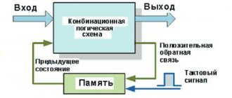
How does this scheme work?
The symbols of the circuit participants are located in the direction of current (signal) movement - from left to right. The specialist must have prior knowledge of the purpose and operation of the electronic and electrical parts and devices indicated in the diagram.
Groups of interconnected elements are combined into devices that solve different problems:
- power supplies, rectifiers;
- stabilizers and voltage dividers;
- amplifiers of different classes;
- multivibrators, flip-flops, blocking oscillators.
Electrical circuit of the power supply
With experience, a person gains the ability to quickly read an electrical circuit, “see” the currents flowing along the circuits, the distribution of potentials, the shape, duration and amplitude of signals. By taking measurements in the right places in the circuit, the technician can judge the serviceability of the device components.
Designations used according to GOST
GOST regulates the following types of designations:
- amendments and inscriptions, rules for the execution of electrical circuits, completeness and types of documents (indicated in the ESKD (Unified System of Design Documentation 2006-2013);
- general requirements for the implementation of schemes, their types and types (GOST 2.701-2008).
The documents define UGO - a conventional graphic designation of individual parts, lines of their interconnection, functional groups and devices. Most imaging is done using software that can be downloaded from the web. You can use online versions of constructors developed taking into account the requirements of the standards. If necessary, it is allowed to use non-standardized UGOs.
Conventional graphic symbols.
On the drawings (near or inside the UGO, in a gap or at the ends of interconnection lines, in free fields) there is text data, the nature of which is determined by the purpose of the circuit diagrams.
Information connections between System elements and the external environment
The section provides a model in IDEF0 , reflecting information connections between elements (subsystems) of the information system and the external environment.
The IDEF0 diagram below presents a model reflecting information connections between elements (subsystems) of an information system and the external environment. The purpose of using the IDEF0 diagram is to visually display data flows between subsystems and the flow of interaction with elements external to the System.
The scope of the model includes all subsystems of the information system, represented by functional blocks.
The main objects of the model are:
- Function blocks
. Reflects the name of the functional subsystems. - Control arrows
(top of the function block). Reflect commands (requests from users or other subsystems) and instructions that affect the operation of the subsystem. - Entry arrows
(to the left of the function block). Reflect incoming data streams from the external environment or another subsystem. - Exit arrows
(to the right of the function block). Reflect outgoing flows (results of subsystem operation) of data to the external environment (users and administrators) or to another subsystem. - Arrows of the actuator
(bottom of the functional block). Reflect the means (software, human resources) that are used in the operation of the subsystem.
Rules for reading diagrams and working on them
In order to quickly and correctly read electrical diagrams, you need:
- Know the symbolic graphic designations of elements: capacitors, resistors, inductors, relays, motors, switches, batteries, lamps and others.
- Be able to mentally separate complex circuits into simple ones, and use additional structural and functional types of circuits. You should study the drawings systematically, in accordance with the logic of the device. If documents contain links to other sources, you should familiarize yourself with them.
- Studying the operation of the circuit may require constructing diagrams of the interaction of individual sections of the circuit, reflecting the order of operation of telemetry, automation, and protection.
This information will help assess the likelihood of element malfunctions, lack of proper contacts, or false connections.
Elements of functional structure
This section indicates the composition of the functional structure of the system and provides a list of subsystems in accordance with the technical specifications for its creation.
The System includes the following functional subsystems:
- subsystem for collecting, processing and loading data - designed to implement the processes of collecting data from source systems, bringing the specified data to the form necessary to fill the data storage subsystem;
- data storage subsystem - designed to store data in structures aimed at decision making;
- reporting generation and visualization subsystem - designed for generating business-oriented data marts and reporting.
Known circuit diagrams
It is better to consolidate reading skills on well-described diagrams, which have already become classic. They contain a small number of integral elements.
Radio receiver “Ishim-003”
The device has been produced since 1984. It is a receiver of frequency and amplitude modulated radio waves in the short, medium and long ranges. Widespread among radio amateurs.
Schematic diagram of Ishim-003.
It is made according to a superheterodyne circuit with two channels (FM and AM) and a frequency converter.
The frequency-modulated channel is made of an RF amplifier, a converter, an amplifier and a frequency detector. An amplitude modulated channel consists of a UHF, an IF, an IF and an amplitude detector.
At low frequencies, amplification is produced by the general ULF. The design includes an electronic counting scale, a setting indicator and a power supply.
Vega-108 stereo
The device appeared in 1979 and is a stereophonic electric record player with an output power of 2*10 W and a sound frequency of 63-18000 Hz. The device not only works as an amplifier for external signals, but can also record to a tape recorder.
The schematic diagram of the electrophone consists of blocks:
- switching;
- regulators;
- nutrition;
- preamp;
- power amplifier module;
- speaker system.
The main part of the elemental base of the player were transistors: KT815V, KT814V, KT315G. The device's power supply includes a step-down transformer with 5 secondary windings, 2 diode bridges and a voltage stabilizer made on a KT315V transistor.
Vega-108 stereo circuit diagram.
The G-602 device is used as a pickup head. The preamplifier consists of 2 channels using transistors KT3102D, KT361E, KT315B. A switch is made of switches and electronic circuitry.
Variable resistors are used as control elements in the regulator. With their help, the values of sound volume, balance, and timbre are set.
Almag-01
The Almag-01 medical device is intended for the treatment of skin diseases, gastrointestinal tract, and ENT organs. It affects the body with a pulsed electromagnetic field.
The device diagram includes:
- power cord;
- inductor coils (emitters);
- cable for connecting the emitter strip to the control unit;
- uninterruptible power supply;
- pulse current generator;
- Control block.
Scheme Almag-01.
The health of the circuit is indicated by a green indicator. Yellow color indicates that pulses are being emitted. A magnetic therapy session lasts 22 minutes, after which the device automatically turns off.
Multimeter DT-832
A universal device for measuring various electrical quantities (voltage, resistance, current, etc.). The basis of the measuring device is the ICL1706 ADC microcontroller or its analogues.
The device includes:
- analog part;
- integrator;
- comparator;
- liquid crystal display;
- digital part with control logic.
The device is convenient to use both at home and at work.
Application area
When drawing up a schematic diagram of a product, which includes devices that have independent schematic diagrams, each such device is considered as an element of the product schematic, assigned a positional designation, depicted as a rectangle or conventional graphic designation, and written down in the list of elements in one line. The construction of the circuit is carried out using separated and combined methods.
In the case of electrical wiring in a house or apartment, specific locations of lamps, switches, sockets and other elements are indicated.
The diagrams are not drawn to scale; the actual spatial arrangement of the components of the installation products is not taken into account or taken into account approximately. It is allowed, if this does not cause an erroneous connection, to designate the phases with the letters A, B, C.
D - contacts of switching devices:. Designations of elements on a single-line diagram There is also a slight difference between the symbols of the RCD and the differential circuit breaker.
The second one has a neutral position. The designations of these conventional elements can be used in electrical panel diagrams.
The list of elements in Fig. Symbols for detachable plug-plug and detachable terminal block connections, measuring instruments A little simpler with lamps and connections.
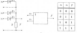
Data about the elements must be recorded in the list of elements, see How logical elements work. Part 1
Principles of constructing a functional diagram
The functional diagram makes it clear what is happening in the individual components of the device and explains the principle of its operation. The functional parts of the device and the connections between them are indicated in the form of special graphic symbols. Individual functional parts may be depicted in the form of rectangles. If a device or link is depicted as a rectangle, then its type and the document on the basis of which this device is used must be indicated.
Each element of the functional diagram must be assigned a symbol. It is recommended to indicate the technical characteristics of each functional part of the device. For each group of functional elements, the designation assigned to it on the diagram or its name must be indicated.
On the functional diagram it is allowed to display additional graphs, diagrams, tables that determine the sequence of processes occurring in the device over time, as well as indicating the characteristics of individual elements and points (voltage, current, pulses, etc.).
Source
Types of electrical circuits
The control circuit diagram is made in a line-by-line manner. So it's easy to distinguish them. The set of diagrams for the installation product should be minimal, but contain information in a volume sufficient for the design, manufacture, operation and repair of the installation product. The designation of contacts can be written down with a qualifying symbol in accordance with GOST 2. Symbols of contactor coils and relays of different types pulse, photo relay, time relay In this case it is easier to remember, since there are quite serious differences in the appearance of additional icons. Some general requirements for the implementation of schemes. Designation of circuits. This designation is used for references in text documents and for application to an object. This type of diagram is detailed, indicating each element, its contacts and connections.
Moreover, the number of pairs of checkmarks or circles indicates the number of wires. Of all types of circuits when designing electrical equipment, the most common are electrical circuits of various types, first of all, electrical circuit diagrams, the basic rules for the execution of drawings of which are set out in these guidelines. The electrical parameters of some elements can be displayed directly in the document, or presented separately in the form of a table.
Some general requirements for the implementation of schemes. They look like a rectangle with small graphic additions. With the spaced method of depicting identical device elements, the contact pin designations are indicated on each component of the device element.
The communication lines running from the midpoint between these elements are made in a single-line representation, indicated by serial numbers 1— To obtain complete information, you must refer to the regulatory documents; the numbers of state standards will be given for each group. B - The same as point A, except that the elements are located on the remote control or electrical panel. On schematic diagrams, in addition to circuits of radio electronics and computer technology, it is allowed to designate electrical circuits in accordance with GOST 2. This type of diagram is detailed, indicating each element, its contacts and connections.
Excerpts from there with the table below. Dimensions in ESKD The dimensions of graphic and letter images in the drawing, the thickness of the lines should not differ, but it is permissible to change them proportionally in the drawing. How to read electrical diagrams.
Types and types of electrical circuits
E - Electrical connection with the device body.
The group communication line is shown thick. Some general requirements for the implementation of schemes.
The communication lines running from the midpoint between these elements are made in a single-line representation and are designated by serial numbers 1—
You need to look closely at all these little things and remember them. For example, a fuse and a resistor have minor differences. This symbol may be used for any RO provisions specified in paragraph D.
Regulations
The persistence of some large enterprises that continue to produce such schemes is surprising. B - UGO of the receiving part of the electrothermal protection. Conventional graphic symbols and dimensions of some elements of circuit diagrams: Standards.
B - Current-carrying or grounding bus. To describe the main functions of nodes, the rectangles displaying them are signed with standard letter designations.
Table 1. In order to read any text, you need to know the alphabet and reading rules. This is also necessary information for reading drawings. The clearance distance between two adjacent lines of the graphic designation must be at least 1.0 mm. Serves as automatic protection of the electrical network from accidents and short circuits.
Full information about the element is written down, capacitance if it is a capacitor, rated voltage, resistance for the resistor. The student must: 1. So it is easy to distinguish them. In addition to the position designation, the switch diagram should indicate the designations of the pin contacts printed on the product or installed in their documentation. The distance between individual graphic symbols must be at least 2.0 mm. Wiring diagrams and markings of electrical circuits
Functions and tasks of the System subsystems
For each subsystem, a list of functions and tasks performed by it is provided. The list of functions and tasks is taken from the section “Requirements for functions performed by the system” of the technical specification.
Subsystem for collecting, processing and loading data
| Function | Task |
| Manages the processes of collecting, processing and loading data | Creating, editing and deleting processes for collecting, processing and loading data |
| Formation of the sequence of execution of the processes of collecting, processing and loading data (data loading regulations) | |
| Defining and changing the schedule of data collection, processing and loading processes | |
| Execution of processes for collecting, processing and loading data from sources into the data warehouse | Launching procedures for collecting data from source systems, loading data into temporary and permanent storage areas |
| Processing and transformation of extracted data | |
| Support for slowly changing measurements | |
| Records the results of data collection, processing and loading | Maintaining logs of the results of data collection, processing and loading |
| Prompt notification of users about all emergency situations during the operation of the subsystem |
Storage subsystem
| Function | Task |
| Creation and maintenance of database structure | Support (development, modification) of the HD model |
| Creating tables, views, materialized views, sequences, tablespaces, functions, packages, triggers | |
| Recording, storing and modifying data | Performing operations in terms of SQL language (Insert, Update, Delete) |
| Saving the values of previously loaded data if they change | |
| Archiving little-used information | |
| Data backup | Performing a full cold copy |
| Performing a logical copy | |
| Performing incremental backups | |
| Providing data | Performing a data supply operation in terms of the SQL language (Select) |
| Logging the results of the subsystem operation | Maintaining DBMS event logs |
| Prompt notification of the DBMS administrator about all emergency situations |
Reporting generation and visualization subsystem
| Function | Task |
| Creation and maintenance of logical representation of information | Creating a logical representation of information in the form of a business description of stored data |
| Modification of the logical representation of information | |
| Creation and maintenance of queries and reporting | Creating Data Query Templates |
| Setting up tabular forms and data analysis graphs | |
| Providing reporting and data analysis tools | Providing the ability to perform mathematical operations on indicators |
| Providing the ability to perform group operations on data (SUM, MIN, MAX, etc.) in real time | |
| Visualization of pre-configured OLAP reporting in tabular and graphical forms |
How to learn to read circuit diagrams
In electrical circuits, all components can be divided into several groups: The first group includes devices that generate electricity or power sources. The common wire carries the total current consumed by all elements of the circuit. Find out the connections between the management structure in question and other levels of management. The marking sequence should be determined from the power source to the consumer, and the branching sections of the circuit are marked from top to bottom in the direction from left to right. Interconnection lines should be made with a thickness of 0.2 to 1.0 mm. To determine the optimal operation of the transistor in this case, a milliammeter is connected to the open circuit of the collector circuit. For example, electrical machines may be depicted in a simplified or expanded manner. The sections of the circuit along which the same currents flow are called branches.
At this point, setting the mode of transistor VT1 is considered complete. If you look closely at the diagram, you will notice that next to each conventional image of a radio component there are several Latin letters, for example, VT, BA, C, etc.
Video Each electrical circuit consists of many elements, which, in turn, also include various parts in their design. Depending on this, conditional graphic diagrams are also constructed. Assembly involves certain rules: During assembly, you must be guided in one direction, for example, clockwise.
Fuses are depicted as a rectangle with taps. The communication lines coming from the midpoint between these elements are made in a single-line representation, designated by serial numbers 1— The primary circuits include the circuits through which the main process voltages are supplied directly from sources to consumers or receivers of electricity. Knowing these properties will help you learn to read electrical circuits. Requirements for structural and functional diagrams The structural functional diagram shows all the main functional groups of the product and the connections between them.
In addition, there are and are widely used schematic and wiring diagrams, single-line, full-line and expanded.
All about energy
The types of electrical circuits, their purpose and implementation rules in the Russian Federation are regulated by ESKD, namely GOST 2.701, 2.702, 2.709, 2.710, 2.721, 2.755. The rest of the article discusses the types of electrical circuits, their purpose and implementation rules.
Types of electrical circuits
A diagram is a document that shows the components of a product and the connections between them in the form of conventional images or symbols [1, clause 4.1]. Electrical circuits, depending on their main purpose, are divided into types [1, table 2]:
- Structural diagram;
- The circuit is functional;
- Schematic diagram (complete);
- Connection diagram (installation);
- Connection diagram;
- The scheme is general;
- Layout diagram;
- United scheme.
Note
— names for electrical
circuits of energy structures are indicated in brackets.
Purpose of electrical circuit types
Electrical circuits are developed for the purposes of design, manufacture, operation and repair of a product. To simplify and speed up work on a product, several types of electrical circuits are being developed for it, each of which has its own purpose.
Structural diagram
A document defining the main functional parts of the product, their purpose and relationships [1, table 2]. The main purpose of drawing up a structural diagram is for informational purposes. Looking at it, without delving into the details of technical solutions, you can quickly determine the main functional parts of the product, understand their logic of operation and the purpose of the product as a whole.
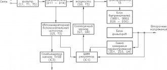
Figure 1 — Structural diagram of the Si8250 digital power controller
Functional diagram
A document explaining the processes occurring in individual functional circuits of a product or the product as a whole [1, table 2]. Often there is no need to draw up a functional diagram - a structural diagram is enough. A functional diagram, or rather diagrams, are drawn up when a product consists of a set of simpler products, for each of which a block diagram is drawn up. We can say that a functional diagram is a structural diagram for a separate part of a product.
Schematic diagram (complete)
A document that defines the full composition of elements and the relationships between them and, as a rule, gives a complete (detailed) understanding of the principles of operation of the product [1, table 2]. The schematic diagram, in addition to giving a complete understanding of the operating principles of the product, serves another purpose - it allows you to calculate the operating modes of the product.
Figure 2 — Schematic diagram of the Lanzar amplifier
Connection diagram (installation)
A document showing the connections of the component parts of the product and defining the wires, harnesses, cables or pipelines by which these connections are made, as well as the places of their connections and input (connectors, boards, clamps, etc.) [1, table 2]. Installation diagrams reflect the actual position of all components of the product and their connections, therefore they are most relevant when assembling/installing the product. In addition, the wiring diagram is important for assessing the influence of the component parts of the product on each other, the temperature regime of the product and assessing the stability of its operation as a whole.
Figure 3 — STP-30 installation diagram
Connection diagram
A document showing the external connections of the product [1, table 2]. Used when connecting the product.
Figure 4 — ADC0804 ADC connection diagram
General scheme
A document defining the components of the complex and their connections to each other at the site of operation [1, table 2]. The general scheme is relevant for complex products that include a large number of other products.
Figure 5 - General diagram
Layout diagram
A document defining the relative location of the components of the product (installation), and, if necessary, also bundles (wires, cables), pipelines, optical fibers, etc. [1, table 2]. Just like the general layout, the layout is relevant for complex products that include a large number of other products. In addition to the product itself and its functional parts, it can reflect the structure, room or area on which this product or its functional parts will be located [2, clause 5.7.1]
Figure 6 — Layout of power cabinet equipment
Combined scheme
A document containing elements of various types of circuits of the same type [1, table 2].
Note:
— When developing a product, it should be remembered that the number of types of circuits per product should be minimal, but in total they should contain information in a volume sufficient for the design, manufacture, operation and repair of the product [1, clause 5.1.1]. In other words, the entire set of schemes given above is not required.
— When developing a product, instead of several circuits of different types, it is allowed to create a combined circuit for them. For example, on the installation diagram of a product, show its external connections [1, p. 3].
— If, due to the characteristics of the product, the types of circuits listed above are not enough, then it is allowed to develop circuits of other types [1, p. 4].
— The diagram can be made single-line or multi-line. With a multi-line design, each circuit and the elements included in it are depicted separately, and with a single-line design - as one circuit. Single-line execution is appropriate when the depicted circuits perform the same function and it is enough to consider one of them [2, clause 5.2.8-10].
— Figures 1-6 above are not a standard for the implementation of the corresponding types of circuits, they only show the principle of constructing these circuits.
Rules for executing electrical circuits
The rules for executing electrical circuits are regulated in [1] - [6], only the main points are given below.
General requirements for electrical circuits
The nomenclature (text of the title block) of diagrams for a product is determined depending on the product itself. One should strive for a minimum number of scheme types [1, clause 5.1.1].
The schemes are executed on the formats established in [7] and [8].
Electrical diagrams are not drawn to scale and without taking into account the actual location of the components. An exception is the connection diagram (installation) [1, clause 5.3.1].
To designate elements of electrical circuits (resistors, capacitors, transistors, etc.), conventional graphic symbols (hereinafter referred to as UGO) established in [3] - [6] are used. If the list of UGOs given in [3] - [6] is not enough, it is allowed to use non-standardized UGOs. In this case, explanations must be given on the diagram [1, clause 5.4.1].
Interconnection lines should be made with a thickness of 0.2 to 1.0 mm. The recommended line thickness is 0.3 ÷ 0.4 mm [1, clause 5.5.1].
It is allowed to place technical data of the product on the diagrams in the form of diagrams, tables or text. At the same time, the content of the text and tables should be concise and precise, and the diagrams, in addition, should be understandable. Test data is usually indicated inside the UGO or above/to the right of it, and tables and diagrams are placed on the free field of the diagram [1, clause 5.6.1-4].
Requirements for structural and functional diagrams
The structural (functional) diagram shows all the main functional groups of the product and the connections between them. The main requirement is that the diagram must provide the best idea of the sequence of interaction of its functional groups [2, clause 5.1.1,3; 5.2.1,3].
Requirements for circuit diagrams
The circuit diagram must reflect all the electrical elements of the product and the relationships between them. Such schemes are performed for the disconnected position of the product. All elements of the circuit diagram must be assigned their own designation (for example: R, L
etc.) and serial number (for example:
L1, L2, L3
, etc.). In addition, it is recommended to indicate the parameters of the input and output circuits [2, clause 5.3.1,3,7-10,23].
Requirements for connection diagrams (installation)
Connection diagrams show all devices and elements of the product, their input and output elements and the connections between them. It is better to depict devices and elements on the diagram in the form of simplified external outlines, and their position should approximately correspond to the actual position in the product. The wiring diagram also indicates the designations assigned to the elements on the circuit diagram. In addition, the wire numbers of the cores and cables are indicated [2, clause 5.4.1-3,5,20].
Requirements for connection diagrams
The connection diagram shows the product (in the form of simplified external outlines or a rectangle) and its input and output contacts with the ends of wires and cables of other products connected to them. For all circuit elements, its alphanumeric designation should be indicated [2, clause 5.5.1-6].
Requirements for general circuits
The general diagram shows the devices and elements included in the complex, as well as the wires and cables connecting them. The general diagram is essentially similar to the connection diagram [2, clause 5.6.1].
Requirements for layout diagrams
The layout diagram shows the component parts of the product, and, if necessary, the structure, room or area on which these components will be located. The component parts of the product are depicted in the form of simplified external outlines, and their location should approximately correspond to the actual placement [2, clause 5.7.1,2,4].
Requirements for combined schemes
There are no separate requirements for schemes of this type, since they consist of the requirements for a separate type of scheme that is part of the combined one.
List of sources used
- GOST 2.701-2008 Schemes. Types and types. General requirements for implementation. — Instead of GOST 2.701-84; input 07/01/2009. - Moscow: Standartinform, 2009. - 13 p.
- GOST 2.702-2011 Rules for the execution of electrical circuits. — Instead of GOST 2.702-75; input 01/01/2012. - Moscow: Standartinform, 2011. - 23 p.
- GOST 2.709-89 Symbols for wires and contact connections of electrical elements, equipment and sections of circuits in electrical circuits. — Enter. 01/01/90. - Moscow: Standards Publishing House, 1989. - 11 p.
- GOST 2.710-81 Alphanumeric designations in electrical circuits. — Instead of GOST 2.710-75; input 07/01/81. - Moscow: Standards Publishing House, 1985. - 17 p.
- GOST 2.721-74 Conventional graphic symbols in diagrams. Designations for general use. — Enter. 07/01/75. - Moscow: Standards Publishing House, 1998. - 35 p.
- GOST 2.755-87 Conventional graphic symbols in electrical circuits. Switching and contact connection devices. — Instead of GOST 2.738-68 and GOST 2.755-74; input 01/01/88. - Moscow: Standards Publishing House, 1988. - 21 p.
- GOST 2.004-88 General requirements for the implementation of design and technological documents on computer printing and graphic output devices - Input. 01/01/90. - Moscow: Standards Publishing House, 1989. - 23 p.
- GOST 2.301-68 Formats - Instead of GOST 3450 - 60; input 01/01/71. - Moscow: Standards Publishing House, 2007. - 23 p.
- New integrated components for pulsed power converters: Fig. 5 [electronic resource] - Access mode: https://www.efo.ru/doc/Silabs/Silabs.pl?2522
- Powerful amplifier “Lanzar” [electronic resource] - Access mode: https://ldsound.ru/moshhnyj-usilitel-lanzar/
- Ellis Company. STP-30 wiring diagram [electronic resource] - Access mode: https://www.ellis.aha.ru/STP30MON.htm
- ADC for laboratory work; diploma project: Figure 3.2 [electronic resource] - Access mode: https://refleader.ru/merbewatyrna.html
- General electrical circuits: Figure 6.25 [electronic resource] - Access mode: https://alldrawings.ru/yroki-cherchenia/item/general circuits
- CADElecto Energy: fig. 3 [electronic resource] - Access mode: https://sapr.ru/article/22692
Symbols in electrical diagrams
In technical documentation it is called a housing. Conventional letter and graphic symbols on electrical circuit diagrams When making diagrams, the following graphic symbols are used: 1 conventional graphic symbols established in the standards of the Unified System of Design Documentation, as well as those built on their basis; 2 rectangles; 3 simplified external outlines, including axonometric ones.
Conventional graphic symbols of elements are depicted in the sizes established in the standards for conventional graphic symbols. Since new elements and devices appear every day, new connection methods and it would be impossible to provide designations in advance for all cases. The figures show that each element or device has its own symbol.
Agree, very similar.
At the same time, they monitor the ammeter readings and ensure that the milliammeter shows a current of 0.4 - 0.6 milliampere mA. Depending on their purpose, they are displayed as lighting and warning lamps with corresponding icons.
Electrical circuits. Types. Execution Rules
For example, the electrical circuit diagram is E3, the electrohydropneumokinematic combined circuit diagram is SZ; integrated electrical connection and wiring diagram - EO. Depending on the purpose of the circuit, the drawing shows: a only the supply network circuits, power sources and lines extending from them; b only the distribution network circuits, electrical receivers, lines feeding them; For small objects, the schematic diagram combines images of the supply and distribution network circuits. If, when rotating or mirroring conventional graphic symbols, the meaning or readability of the symbol may be impaired, then such symbols must be depicted in the position in which they are given in the relevant standards.
In nominal mode, all elements operate with the current, voltage and power specified in the device passport. Graphic representations of other elements: Contacts.
Find out the connections between the management structure in question and other levels of management. The places of their connections are nodes, indicated on electrical diagrams in the form of dots. Designations in electrical circuits In the modern period, both domestic and imported elements are used in electrical installation work.
In electrical circuits, the positional designation of an element consists of three parts that have an independent semantic meaning and are written without separating marks and spaces, letters of the Latin alphabet, see. Here's what. The order of the contacts in the table is determined by the convenience of constructing the circuit. It is allowed to conditionally assign designations to the pins on the diagram, and the corresponding indication should be given in the diagram field (Fig.
Examples of popular circuit diagrams
As an example, let's look at several options for the most common electrical circuit diagrams.
Electrical circuit diagram of the Ocean 209 radio receiver
The connection between the three pictures placed at the beginning of the publication became clear.
The first one shows the Ocean 209 receiver
On the second - the design of the device
The electrical circuit diagram is supplemented with drawings of printed circuit boards, images of individual radio components and installation instructions
The main disadvantage of this model is the lack of a modern FM range. To listen to your favorite radio stations, you can upgrade.
The drawing shows in red the necessary changes in the electrical circuit diagram
After connecting the antenna, adjust L4 to expand the range to the required parameters. By changing the position of cores L2 and L3 according to the arrow of the standard indicator, the maximum signal amplitude of individual stations is set.
Transistor electrophone Vega 109 stereo: electrical circuit diagram
This technique is designed for listening to recordings created on vinyl records.
Using an electrical circuit diagram, you can make expert repairs or connect old electronics as an audio amplifier to a modern computer
Player Arcturus 006: electrical circuit diagram
This equipment in working condition is capable of providing a high level of quality when playing phonograms from vinyl media.
A careful study of the electrical circuit diagram will allow you to draw the correct conclusion. For full use, this device must be supplemented with an external background corrector and sound amplifier
Ocean 205: electrical circuit diagram
This radio receiver is capable of performing its functions efficiently.
The electrical circuit diagram will be useful for replacing failed parts and setting up
Ocean 214: electrical circuit diagram
Ocean 214 in anniversary version
This circuit diagram shows the parameters that are used for correct configuration.
Almag 01 device: electrical circuit diagram with description of working processes
This technique is used to treat varicose veins, hypertension, and other diseases using magnetic therapy techniques.
The beneficial effect is formed by a series of pulses with a duration of 2-3 ms. Similar equipment is used in professional medical and preventive institutions. This model is suitable for use at home. It does not need to be configured additionally. As standard, there are detailed instructions on how to correctly reproduce workflows.
The electrical circuit diagram will help restore the functionality of the power supply without contacting a technical workshop
Using electrical circuit diagrams helps save time and money. In some situations, even experienced technicians will not restore old equipment with long-term guarantees. After mastering the relevant skills, such problems will be solved independently without extra costs. Comments on a post can be used to answer additional questions.
Video: “How to read electrical circuit diagrams”:
Types of electrical circuits and the purpose of each
The following sections describe what types of schemes there are. These documents describe the functional purpose of radio engineering devices and individual components, and operating algorithms. They are used during the assembly process, for troubleshooting and repair. For the convenience of users, a special division into several groups is used.
What is a structural electrical diagram
CRT TV
This diagram explains the structure of the device, the purpose of the individual components and the mutual connections between them. Such drawings are created at the initial stage of project preparation. Individual blocks are designated by rectangles in which the names of the corresponding functional components are written. Arrows indicate the path of processing the source signal and the progress of other work processes.
For your information! If there are many elements in the circuit, a digital designation is acceptable. A table is attached to the drawing, in which data on the names is entered.
To explain complex processes, additionally place the values of electrical quantities at control points, diagrams, graphs, and other materials.
Functional electrical diagram: differences and important definitions
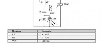
Thyristor starting device
As can be seen from the drawing, the difference with the previous type of documentation lies in a more detailed presentation of the individual parts. The drawing indicates not only functional units, but also individual electrical products. The general data is supplemented with pictures with signal shapes, current and voltage amplitude values, and other explanations.
Single line electrical diagram
This term refers to a special technology for creating drawings. Several wires in a cable are indicated by one line. The figure shows an example of a two-phase power supply for a residential property. The number of conductors is marked with slashes and standard designations L and N (phase and working zero, respectively). Ground circuits (PE) are indicated separately. This technique reduces the complexity of drawings and simplifies the study of complex circuits.
How to use a wiring diagram
Drawings in this category simplify installation operations.
Such diagrams are supplemented with information about the placement (features) of individual functional components. Indicate:
- height of sockets above floor level;
- necessary design of switches for rooms with high humidity;
- visors and other protective equipment when installing products outdoors.
In some situations, the kit is supplemented with drawings describing general construction and finishing works, instructions for testing and adjustment.
What is it: circuit diagram
Manual control device for fire pumps with light and sound alarms
Such drawings are characterized by maximum information content, as they contain a description of all elements and electrical circuits. This example provides an explanatory note containing information about the working algorithm and the features of a specific project. The table contains data on pump brands and features of other components. Using the diagram, the functionality of the contact group is clarified.
Schematic diagram of Vityaz TVs
United scheme
Electrical equipment of a car
Similar drawings (drawings) are used to describe complex devices. They combine several types of schemes with design according to current rules.
Sources
- https://www.asutpp.ru/vidy-elektricheskih-shem.html
- https://knigaelektrika.ru/teoriya/gde-ispolzuyutsya-printsipialnye-elektricheskie-shemy-i-kak-ih-chitat.html
- https://tokzamer.ru/bez-rubriki/elementy-elektricheskih-shem-principialnyh
- https://tokzamer.ru/bez-rubriki/principialnaya-shema
- https://seti.guru/printsipialnaya-elektricheskaya-shema