There are several classes of electrical converters, among which the so-called inductive analogues have found practical application. In them, energy conversion occurs due to the conversion of induction windings, which are an integral part of the unit itself. The windings are located on two elements - the stator and the rotor. So, what is the difference between a stator and a rotor (what are they and what are their functions?).
The simplest definition of the two parts of the converter is their functionality. Everything is simple here: the stator (of an electric motor or generator) is a stationary part, the rotor is a movable part. In most cases, the latter is located inside the former, and there is a small gap between them. There are so-called units with an external rotor, which is a rotating ring with a stationary stator inside.
Types of converters
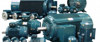
Why is it so important to consider the types in order to understand how the stator of an electric motor differs from its moving part. The thing is that electric motors have a lot of design features, the same applies to generators (these are converters of mechanical energy into electrical energy, electric motors have the opposite functionality).
So, electric motors are divided into AC and DC devices. The former, in turn, are divided into synchronous, asynchronous and collector. For the former, the angular speed of rotation of the stator and rotor are equal. For the latter, these two indicators are unequal. In collector types, the design contains a so-called frequency converter and the number of phases of a mechanical type, which is called a collector. Hence the name of the unit. It is he who is directly connected to the windings of the motor rotor and its stator.
DC machines have the same commutator on the rotor. But in the case of generators, it performs the functions of a converter, and in the case of electric motors, it functions as an inverter.
If an electric unit is a machine in which only the rotor rotates, then its name is one-dimensional. If two elements rotate in opposite directions at once, then this apparatus is called two-dimensional or birotative.
Pole rotation using alternating current
Pole rotation using alternating current
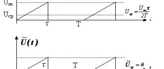
The polarity is constantly reversed using alternating current (AC). Next we will see how the rotor is replaced by a magnet, which rotates under the influence of induction. Alternating current plays an important role here, so it will be useful to provide some brief information about it here:
Alternating current - AC
Alternating current is understood as an electric current that periodically changes its direction in a circuit so that the average value of the current over the period is zero. A rotating magnetic field can be created using three-phase power. This means that the stator is connected to a three-phase AC source. A complete cycle is defined as a 360 degree cycle. This means that each phase is located at an angle of 120 degrees relative to the other. The phases are depicted as sinusoidal curves, as shown in the figure.
Three-phase alternating current
Three-phase power is a continuous series of overlapping alternating current (AC) voltages.
Pole reversal
The following pages explain how the rotor and stator interact to make the motor rotate.
For clarity, we replaced the rotor with a rotating magnet and the stator with coils. On the right side of the page is an image of a two-pole three-phase electric motor. The phases are connected in pairs: the 1st phase corresponds to coils A1 and A2, the 2nd phase - B1 and B2, and the 3rd phase corresponds to C1 and C2. When current is applied to the stator coils, one of them becomes the north pole, the other becomes the south pole. Thus, if A1 is the north pole, then A2 is the south pole.
AC Power
The windings of phases A, B and C are located at an angle of 120 degrees relative to each other.
The number of poles of the electric motor is determined by the number of intersections of the winding field with the rotor field. In this case, each winding is crossed twice, which means that we have a two-pole stator. Thus, if each winding appeared four times, it would be a four-pole stator, etc.
When electric current is applied to the phase windings, the motor shaft begins to rotate at a speed determined by the number of poles (the fewer poles, the lower the speed)
Rotor rotation
The following describes the physical principle of operation of an electric motor (how the rotor rotates inside the stator). For clarity, let's replace the rotor with a magnet. All changes in the magnetic field occur very quickly, so we need to break the whole process into stages. When three-phase alternating current passes through the stator windings, a magnetic field is created in it, resulting in mechanical forces that cause the rotor to rotate in the direction of rotation of the magnetic field.
Once it starts rotating, the magnet will follow the changing magnetic field of the stator. The stator field is changed so as to maintain rotation in one direction.
Asynchronous electric motors
To understand the concepts of a motor rotor and its stator, it is necessary to consider one of the types of electrical converting machines. Since asynchronous electric motors are most often used in production equipment and household appliances, it is worth considering them.
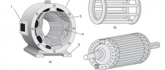
So, what is an asynchronous electric motor? This is usually a cast iron body into which a magnetic circuit is pressed. It contains special grooves into which the stator winding, assembled from copper wire, is placed. The grooves are shifted relative to each other by 120º, so there are only three of them. They form three phases.
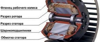
The rotor, in turn, is a cylinder assembled from steel sheets (stamped electrical steel) and mounted on a steel shaft, which in turn is installed in bearings when assembling the electric motor. Depending on how the phase windings of the unit are assembled, the motor rotors can be phase or squirrel-cage.
- A phase rotor is a cylinder on which coils are assembled, shifted relative to each other by 120º. At the same time, three slip rings are installed in its design, which do not come into contact with the shaft or with each other. The ends of three windings are connected to the rings on one side, and graphite brushes on the other, which are located in sliding contact relative to the rings. An example of such a machine is crane electric motors with a wound rotor.
- The squirrel-cage rotor is assembled from copper rods that fit into grooves. At the same time, they are connected with a special ring made of copper.
Speed control of asynchronous motors
To regulate the rotation speed of asynchronous electric motors and control their operating modes, the following methods exist:
- Frequency - when the frequency of the current in the electrical network changes, the rotation speed of the electric motor changes. For this method, a device called a frequency converter is used;
- Rheostat - when the resistance of the rheostat in the rotor changes, the rotation speed changes. This method increases the starting torque and critical slip;
- Pulse is a control method in which a special type of voltage is supplied to the motor.
- Switching the windings during operation of the electric motor from a star circuit to a delta circuit, which reduces starting currents;
- Control by changing pole pairs for squirrel-cage rotors;
- Connecting inductive reactance for wound-rotor motors.
With the development of electronic systems, the control of various asynchronous electric motors is becoming more efficient and accurate. Such engines are used everywhere in the world, the variety of tasks performed by such mechanisms is growing every day, and the need for them is not decreasing.
Operating principle of the electric motor
- Detailed description of the operating principle of different types of electric motors:
- Operating principle of a single-phase asynchronous electric motor
- Operating principle of a three-phase asynchronous electric motor
- Operating principle of a synchronous electric motor
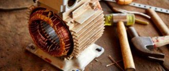
Carrying out repairs
Any electrical equipment, over time, is characterized by failures in its operation. The causes of breakdowns can range from simple pollution to exposure to external factors.
In case of malfunction, start repairing the electric motor by cleaning or purging the stator elements. Then, after removing dirt and dust, proceed to removing the product body to replace the winding. On a lathe or using a chisel, the front part of the stator rewind is cut off.
To soften the insulating material, the stator should be accelerated to a temperature of about 200 degrees, after which the winding is removed, the coil is removed and the grooves are cleaned. After disassembling the electric motor, a new stator winding is installed using ready-made templates.
After installing the coil, it is varnished, followed by drying at a temperature of 150 degrees Celsius for at least two hours.
Checking the electric motor for resistance between the housing and the winding is carried out after all parts of the stator have dried. Adjustment of the equipment to the required parameters is possible by selecting a cable for rewinding.
Classification of electric motors
| Rotating electric motor | ||||
| Self-switching | Externally switched | |||
| Mechanically switched (collector) | Electronically switched 1 (valve 2, 3) | Asynchronous electric motor | Synchronous motor | |
| Alternating current | Direct current | AC 4 | Alternating current | |
|
|
|
|
|
| Simple electronics | Rectifiers, transistors | More complex electronics | Complex electronics (CP) | |
- This category does not represent a separate class of electric motors, since the devices included in the category under consideration (BDDC, VRM) are a combination of a brushless motor, an electrical converter (inverter) and, in some cases, a rotor position sensor. In these devices, the electrical converter, due to its low complexity and small dimensions, is usually integrated into the electric motor.
- A valve motor can be defined as an electric motor that has a rotor position sensor that controls a semiconductor converter that performs coordinated commutation of the armature winding [5].
- A DC valve motor is a DC electric motor, the valve switching device of which is an inverter controlled either by the rotor position, or by the phase of the voltage on the armature windings, or by the position of the magnetic field [1].
- The electric motors used in BLDC and VRD are AC motors, and due to the presence of an electric converter in these devices, they are connected to a DC network.
- The stepper motor is not a separate class of motor. Structurally, it is a PMSM, SRD or hybrid SRD-PM.
- CMDC - commutator DC motor
- BLDC – brushless DC motor
- EP - electrical converter
- DPR - rotor position sensor
- VRD - switched reluctance engine
- ADKR - asynchronous motor with squirrel-cage rotor
- ADFR - asynchronous motor with wound rotor
- SDOV - synchronous motor with excitation winding
Motor stator
The stator is the stationary electrical component of an electric motor. It includes several windings, the polarity of which constantly changes as alternating current (AC) passes through them. Thus, a combined stator magnetic field is created.
All stators are installed in a frame or housing. The stator housing of Grundfos electric motors for electric motors up to 22 kW is most often made of aluminum, and for electric motors with higher power - from cast iron. The stator itself is installed in the stator housing. It consists of thin plates of electrical steel wrapped in insulated wire. The core consists of hundreds of such plates. When power is applied, alternating current passes through the windings, creating an electromagnetic field perpendicular to the rotor conductors. Alternating current (AC) causes the magnetic field to rotate.
The stator insulation must comply with the requirements of IEC 62114, which provides different protection classes (temperature levels) and temperature change (AT). Grundfos electric motors have protection class F, and when the temperature increases, class B. Grundfos produces 2-pole motors with power up to 11 kW and 4-pole motors with power up to 5.5 kW. Grundfos purchases more powerful electric motors from other companies whose product quality meets Grundfos standards. For pumps, stators with two, four and six poles are mainly used, since the speed of the electric motor shaft determines the pressure and flow of the pump. The stator can be manufactured to handle different voltages, frequencies and output powers, as well as a variable number of poles.
Types of electric motors
Commutator motors
A commutator machine is a rotating electrical machine in which at least one of the windings involved in the main energy conversion process is connected to a collector [1]. In a commutator motor, the brush-commutator assembly serves as a rotor position sensor and a current switch in the windings.
Universal electric motor
DC brushed motor
Brushless motors
Brushless motors may have slip rings with brushes, so there is no need to confuse brushless and brushless motors.
A brushless machine is a rotating electrical machine in which all electrical connections of the windings involved in the main energy conversion process are carried out without sliding electrical contacts [1].
Asynchronous electric motor
Synchronous electric motor
Stator and rotor in asynchronous motors
Three-phase asynchronous motors have their own characteristics; the rotor and stator in them differ from those used in other types of electric motors. For example, the rotor can have two designs: squirrel-cage and phase. Let us consider the structural features of each of them in more detail. However, first, let's briefly understand how an induction motor works.
A rotating magnetic field is created in the stator. It induces an induced current on the rotor and thereby sets it in motion. Thus, the rotor always tries to “catch up” with the rotating magnetic field.
It is also necessary to mention such an important feature of an asynchronous motor as rotor slip. This phenomenon lies in the difference between the rotor speed and the magnetic field created by the stator
This is explained precisely by the fact that current is induced in the rotor only when it moves relative to the magnetic field. And if the rotation speeds were the same, then this movement simply would not occur. As a result, the rotor tries to “catch up” with the magnetic field in speed, and if this happens, then the current in the windings ceases to be induced and the rotor slows down. At this moment, the force acting on him grows, he begins to accelerate again. This is how the effect of stabilizing the rotation speed is obtained, for which these electric motors are in great demand.
Squirrel cage rotor
It is also a structure consisting of metal plates that act as a core. However, instead of a copper winding, there are rods or rods installed there that do not touch each other and are short-circuited with metal plates at the ends. In this case, the rods are not perpendicular to the plates, but are directed at an angle. This is done to reduce magnetic field and torque pulsations. In this way, short-circuited turns are obtained, hence the name.
Slip rotor
The main difference between a wound rotor and a squirrel-cage rotor is the presence of a three-phase winding, laid in the grooves of the core and connected in a special collector with three rings instead of lamellas. These windings are usually connected in a star. Such electric motors are more labor-intensive to manufacture due to the complexity of the design, but their starting currents are lower than those of squirrel-cage motors, and they are also better adjustable.
We hope that after reading this article you no longer have any questions about what the rotor and stator of an electric motor are and what their operating principle is. Finally, we recommend watching a video that clearly discusses this issue:
Basic parameters of the electric motor
Motor torque
Torque (synonyms: torque, torque, moment of force) is a vector physical quantity equal to the product of the radius of the vector drawn from the axis of rotation to the point of application of the force and the vector of this force.
,
- where M is torque, Nm,
- F – force, N,
- r – radius vector, m
,
- where Pnom is the rated power of the engine, W,
- nnom - rated rotation speed, min -1 [4]
Initial starting torque is the torque of the electric motor at start-up.
1 oz = 1/16 lb = 0.2780139 N (N) 1 lb = 4.448222 N (N)
torque is measured in ounce-force per inch (oz∙in) or pound-force per inch (lb∙in)
1 oz∙in = 0.007062 Nm (Nm) 1 lb∙in = 0.112985 Nm (Nm)
Motor power
Motor power is the useful mechanical power at the motor shaft.
Mechanical power
Power is a physical quantity that shows how much work a mechanism does per unit of time.
,
- where P is power, W,
- A – work, J,
- t—time, s
Work is a scalar physical quantity equal to the product of the projection of the force on the direction F and the path s traversed by the point of application of the force [2].
,
For rotational movement
,
- where is the angle, rad,
,
- where is the angular velocity, rad/s,
In this way, you can calculate the value of mechanical power on the shaft of a rotating electric motor
Electric motor efficiency
The efficiency of an electric motor is a characteristic of the machine’s efficiency in converting electrical energy into mechanical energy.
Motors used in industry
Both types of motors are successfully used in industry: asynchronous with a squirrel-cage rotor, and synchronous commutator.
The first type of device has important advantages:
- Low price;
- Reliability and durability;
- Easy to use.
There are also disadvantages:
- Impossibility of smooth control of armature speed;
- Low rotation speed - limit 3000 rpm. in networks with a frequency of 50Hz;
- Large starting currents.
However, the advantages of these products far outweigh their disadvantages.
For your information. Asynchronous motors are used in those devices that require constant operating modes of industrial or transport equipment. For example, in drives of various pumps, belt conveyors, in ventilation systems, in lifting mechanisms. The niche of asynchronous electric machines occupies 65-75% of the total volume of electric motors used.
Synchronous commutator motors have their advantages:
- Possibility of smooth, stepless change of rotation speed;
- Great power;
- High rotation speed.
Disadvantages inherent in commutator electric motors:
- Relatively high cost;
- Sliding contacts of the armature commutator, reducing operational reliability and reducing the service life of the machine;
- Frequent maintenance required.
They are used where a smooth change in angular speeds is necessary: these are machine tool drives, traction motors of electric vehicles, and precision installation systems.
Both types of engines are widely used in industry and everyday life. For their long-term and trouble-free operation, it is necessary to carry out routine maintenance, and, if necessary, restoration repairs, including rewinding the stator and rotor windings.
Comparison of characteristics of externally commutated electric motors
Below are comparative characteristics of externally commutated electric motors from the perspective of application as traction motors in vehicles.
| Parameter | ADKR | SDPMP | SDPMW | SRD-PM | SDOV |
| Consistent power throughout the entire speed range | |||||
| Efficiency (efficiency) over the entire operating range |
In accordance with the above indicators, a hybrid synchronous electric motor, namely a synchronous reluctance electric motor with built-in permanent magnets, is most suitable for use as a traction motor in the automotive industry (the choice was made for the BMW i3 & BMW i8 concept cars). The use of reactive torque provides high power in the upper speed range. Moreover, such an engine provides very high efficiency over a wide operating range [7]. |
Definition
From the point of view of electrical engineering, a classic rotor is a rotating cylindrical body with the following structure:
- Shaft made of durable tool steel with at least two bearings, one each at the front and rear;
- Cores made of thick metal plates;
- Coils wound on cores assembled from plates;
- A collector or a pair of special conductive rings.
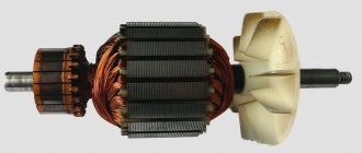
For forced air cooling of a part rotating very often at high speed, an impeller located at one of its ends is used. In generators, rotation is transmitted to the rotor from a turbine connected to it through a common shaft, or from a running engine using a pulley on which a flexible and durable belt is worn (V-belt drive).
So, the main function of the rotor is rotation relative to the stationary part. In electrical engineering, such a stationary part is the stator. Together, the rotor and stator are the most important components of electric motors and alternators.
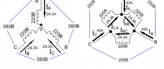
Connection
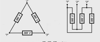
The stator windings of a three-phase ADKR can be connected in a “delta” or “star” circuit. In this case, the sprocket requires a higher voltage than the triangle.
Please note that an electric motor connected in different ways to the same network consumes different power. Therefore, you cannot connect an electric motor designed for a star circuit according to the delta principle. But in order to reduce starting currents, you can switch the star-delta contacts during the start-up, but then the starting torque will also decrease.
The connection diagrams are clear from Figure 4.
Rice. 4. Connection diagrams
To connect a three-phase electric motor to a single-phase current, phase-shifting elements are used: capacitors, resistors. For examples of such connections, see Figure 5. You can use either a star or a triangle.
Rice. 5. Examples of connection diagrams for a single-phase network
In order to control the operation of the motor, additional devices are connected to the stator electrical circuit.
Differences between electric motors in industrial production
Large enterprises with large production areas require equipment operating at high capacities. The technical characteristics of electric motors allow such machines to operate at powers ranging from 1 to 2.5 kW.
- Details about scissor lift
- How to choose a monument?
Why do you need online personnel testing?
In woodworking production, machines of three-phase type and asynchronous operating principle are used. At the same time, they operate without problems at a household voltage of 220 Volts.
Distinctive features of such engines are:
- high power performance with small dimensions;
- increased rotation speed;
- protection from moisture;
- durability and performance.
Best answers
Elektroburatino:
You see, dear Sergey XXX, the question, as I understand it, is a tricky one... Most likely, NOTHING!! ! This is the same name for a part of an electric current generator or an electric motor... I just don’t understand one thing - WHY ARE SUCH QUESTIONS NEEDED?? ? Do you really need answers to these questions? ? Or did you just want to flirt (make fun)?!..
Larisa Dementieva:
Is it true? The rotor is something that is in rotation, and the anchor forces it to remain in stagnation.
Vasya:
armature in DC motors, rotor in AC motors.
Sailor:
This is the name of one part that rotates inside the stator. Difference. There is no winding on the rotor, but there is one on the armature.
realist:
The rotor in DC electric machines is called an armature.
Amir Kstaubaev:
The rotor is the entire rotating part of the electric motor. engine (from the beginning of the motor shaft to the end of the shaft!!! and the armature is that part, round, where exactly the winding with steel plates goes where the EMF is formed!!!! (The rotor is the entire rotating part of the electric motor. Entirely. And the armature is that part of the rotor , where the winding of the electric motor is located in which the EMF is induced. In this photo, the armature along with the windings is indicated by the number four.)
Anatoly Lapshov:
unfortunately, the armature and the rotor are completely different parts, for some reason they don’t put a rotor on the electromagnet, and in non-rotor asynchronous motors there is a short-circuited armature, also now they call a die, but is it possible to cut a thread with a die without a tool? Yes, of course, people who studied in at the crossings it seems to them that all the same educated people were kicked out