Cable laid over the air
Often, to organize power supply in outbuildings, sheds, garages, and local areas, the cable is pulled through the air. If the wiring distance is more than 25 m, install additional support.
When laying a cable through the air, it is important to protect it from external influences: ultraviolet radiation, temperature changes, and precipitation. These factors negatively affect the most commonly used PVC braid, causing it to crack.
To extend the service life of the cable when laid overhead, it is enclosed in a corrugated metal or polyethylene pipe.
Materials used when laying VBBShV armored cable in the ground:
— corrugated PVC or HDPE pipe; — sleeves; — couplings and heat-shrinkable tubes (HERE); — PZK tile; - signal tape. they can also be purchased in our online store.
— Corrugated pipes are used for additional protection when laying armored cables in trenches. Corrugated pipe is often used in the private sector in areas with high humidity. The VBBbShv cable is not resistant to ultraviolet radiation, therefore, at the point where the cable exits over the trench, the cable can be pulled into a HDPE corrugated pipe, which is resistant to ultraviolet radiation, or a PVBbShv cable (PVBbShv), whose protective sheath is also resistant to ultraviolet radiation, can be used. — When connecting armored cables to each other, couplings and sleeves are used. — When closing an armored cable in a trench, a PZK polymer tile is laid on top of the cable. — The signal tape is laid on top of the PZK tile.
Ways to organize wiring inside the house
There are several options for performing internal wiring.
Connecting different cables inside
Wire welding
The SIP conductor is broken and connected to the VVGng cable by twisting and reinforcement by soldering. The technique is not reliable, as it can lead to fires.
Connecting various conductors with fittings
The coupling of SIP and VVGng is carried out using standard reinforcing bars, piercing clamps or other elements near the insertion point. It is unacceptable to use SIP in a residential area - it supports combustion processes.
Through the difavtomat
The connection diagram provides for the use of a two- or four-pole differential circuit breaker. The device is located in a separate sealed box. The cable is laid from the main line to the box and connected to VVGng in a corrugation.
To increase protection, a machine with a rating higher than the distribution board is used. This way, if there is a short circuit or overload, you can restore the line without leaving your home. Another device is installed outside, de-energizing the internal cable and preventing fire.
FAQ
Question No. 1. Is it possible to lay cables with a much larger cross-section than calculated according to the tables?
Yes, you can if you got them for free or very cheap, otherwise it’s an extra financial expense. In this case, take into account the possibility of inserting the ends into the control panel and securing them to the contacts.
Question No. 2. If there is a cable to be laid in the ground, can I lay it over the air?
You can, but you need to take into account its increased weight, be sure to use a cable suspension and the distance between the supports is preferably up to 10 m.
Question No. 3. Is it possible to lay AVVG cable in the ground?
Yes, this cable has reliable waterproofing, but without armored tape, so it must be laid in pipes.
Question No. 4. For a 380 V network, can two AVK cables be used?
To do this, you will need to connect the coaxial sheath of one cable to the third phase, and the sheath of the second cable to the grounded neutral; such a scheme is allowed.
Question No. 5. It is prohibited to lay a cable under the foundation, but can it be laid up to the shield along the wall so as not to drip around the building?
It all depends on the specific conditions at the site; when leaving the ground, the cable up to a height of 1.8 m must be in a protective box or pipe. Walk at a distance of 90 cm from windows and doors, if these conditions are met, do it.
Cable for laying underground 15 kW
Excavation work and cable installation require strict adherence to the standards established by the rules of the PUE and PTEEP.
The criteria for selecting cables for laying in trenches are as follows:
- soil type. This criterion is important for assessing the degree of freezing and natural deformations of various sections of the cable route;
- soil corrosion activity, which is characterized by humidity and acidity;
- operating conditions, including the proximity of foundations and green spaces, roads and railways, oil/gas/heat pipelines, power lines and electrified transport.
Cable products can be laid underground, either protected by armor or without special protective coverings. The classification of types of cables for laying in the ground (trenches) is also made according to the insulation material, which can be made:
- made of PVC;
- made of cross-linked polyethylene (XPE);
- made of paper impregnated with special compounds.
The minimum depth of underground installation of cable products is regulated by regulatory documentation and depends on the operating parameters of the power line and the type of soil. For example, the depth of the trench for cables up to 20 kV should be at least 0.7-0.8 m, up to 35 kV - 1 m.
Armored grades usually do not require additional protection when installed underground. When installing power lines from unarmored grades, as well as when it is necessary to cross roads or railways with armored cables, it is possible to use several types of protective structures:
- concrete slabs that are laid on top of a layer of soft soil or sand of at least 0.1 m. To protect power lines from 35 kV, slabs with a thickness of at least 50 mm are used;
- brickwork, which is installed similarly to concrete slabs;
- asbestos-cement or concrete, steel, ceramic or plastic pipes (corrugated hoses) made of low-density polyethylene (HDPE) or PVC.
Signal tape of the usual or protective type (LS or LZS) is an element of additional protection of power lines from mechanical damage.
Brands of armored cables for laying in the ground
Selecting brands of armored cables for laying in the ground is the optimal solution to ensure reliable operation of underground power lines.
Laying an armored cable in the ground usually does not require additional protective equipment. Products of this type have excellent resistance to mechanical damage, moisture, rodents and other external influences. Let's consider the most popular brands used when laying armored cable underground in Table 1.
| Criterion/brand | VBBShv | VVBG | PvBbShv | PvKShp | SBL | CSKl |
| Number of cores | 1-5 | 2-5 | 1-5 | 3.4 | 1,3,4 | 3 |
| Core cross-section, mm2 | 2,5-625 | 1,5-240 | 2,5-240 | 16-240 | 16-800 | 25-240 |
| Insulation | PVC | PVC | POA | POA | paper | paper |
| Screen | No | No | No | No | electrically conductive paper | electrically conductive paper |
| Armor | 2 steel strips | 2 steel strips | 2 steel strips | round galvanized steel wire | 2 steel strips | round galvanized steel wire |
| Outer shell | PVC hose | No | PVC hose | PET hose | fibrous materials | fibrous materials |
| Voltage, kV | until 6 | up to 1 | until 6 | up to 1 | to 10 | to 10 |
| Limit long-term core heating temperature, °C | 70 | 70 | 90 | 90 | 80 | 80 |
| Features of laying in the ground | In soils with any degree of corrosive activity, incl. with the presence of stray currents. Tensile loads are not allowed. Can be laid in horizontal and inclined routes | In soils with any degree of corrosive activity, incl. with the presence of stray currents. Significant tensile loads are not allowed. Installation in damp environments is possible. Without restrictions on levels on the cable route, incl. on vertical sections | In soils with any degree of corrosive activity, incl. with the presence of stray currents. Tensile loads are not allowed. Do not lay in heaving and subsidence soils. Without restrictions on levels on the cable route, incl. on vertical sections | In soils with any degree of corrosive activity, incl. with the presence of stray currents; in soils with a high probability of deformation (landslides, frozen soils). Without restrictions on levels on the cable route, incl. on vertical sections | In soils with any degree of corrosive activity, incl. with the presence of stray currents. Tensile loads are not allowed. Without restrictions on levels on the cable route, incl. on vertical sections | In soils with any degree of corrosive activity, incl. with the presence of stray currents; in soils with high humidity, bulk, swampy, heaving, frozen. Without restrictions on levels on the cable route, incl. on vertical sections |
What kind of cable can be laid underground?
Quite often, our clients receive questions about the possibility of laying this or that brand underground (in trenches). We have selected the most common of them in order to competently answer them within the framework of this article.
? Is it possible to lay VVGng cable in the ground?
VVGng cable is not recommended for use when laying underground power lines without additional protection from mechanical impact. However, laying VVGng in a HDPE pipe in the ground is permissible.
? Is it possible to lay VVG cable in the ground?
Similar to the VVGng brand, this cable does not have protective coverings, therefore, its installation in underground trenches is not recommended without additional protection. Installation in a pipe is acceptable.
? Is it possible to lay SIP cable in the ground?
This brand belongs to the group of self-supporting cables that are used in the process of installing overhead power lines. According to PUE-6, clause 2.1.48 “Wires and cables should be used only in those areas that are specified in the standards and technical specifications for cables (wires).”
? Is it possible to lay the KG cable in the ground?
The KG cable is designed for connecting moving mechanisms. Its laying in the ground in an open way is unacceptable according to PUE-6 clause 2.1.48.
? In which pipes are cables laid in the ground?
To protect unarmored grades that are used for installing power lines in the ground, double-walled corrugated pipes and technical polyethylene pipes are most often used. Steel pipes are not permissible for laying outdoors (according to PUE-6 clause 2.1.78)
Installation of external electrical wiring
Any technical work related to construction is carried out in accordance with the developed project, which is carried out by specialists. To connect to the power grid, you must submit an application to the energy supply service that serves the building area. The document must indicate the optimal power and voltage required by the user.
The numbers can be calculated based on the total power of the estimated energy consumption of all electrical appliances. Based on this data, the relevant authorities issue a permit in accordance with the technical data, which describes the permissible power, voltage, wire cross-section, grounding rules, as well as protective and fixing equipment.
To connect a house to a 15 kW power grid, a voltage of 230-400 V is required, and the meter must have the appropriate machines.
Why do you need to calculate the cable cross-section?
The following requirements apply to electrical networks:
- safety;
- reliability;
- efficiency.
If the selected cross-sectional area of the wire is small, then the current loads on the cables and wires will be large, which will lead to overheating. As a result, an emergency may occur that will damage all electrical equipment and become dangerous to the life and health of people.
If you install wires with a large cross-sectional area, then safe use is ensured. But from a financial point of view there will be cost overruns. The correct choice of wire cross-section is the key to long-term safe operation and rational use of financial resources.
A separate chapter in the PUE is devoted to the correct selection of a conductor: “Chapter 1.3. Selection of conductors based on heating, economic current density and corona conditions.”
The cable cross-section is calculated based on power and current. Let's look at examples. To determine what wire cross-section is needed for 5 kW, you will need to use the PUE tables (“Electrical Installation Rules”). This directory is a regulatory document. It states that the choice of cable cross-section is made according to 4 criteria:
- Supply voltage (single-phase or three-phase).
- Conductor material.
- Load current, measured in amperes (A), or power - in kilowatts (kW).
- Cable location.
What cable is needed to connect the house to the electrical network: parameters
In the process of connecting a house to the power grid, many conditions arise that must be taken into account in order for the supply of electricity to be stable and long-term. One of the most important elements is the correct choice of cable type from the power line to the distribution panel in the house. Let's look at the article about what cable is needed to connect your home to the power grid.
Parameters to consider when choosing a cable
First of all, determine the current loads that will pass through this cable in order to determine the thickness of the wires; professionals call this parameter the cross-section of the wires. Uninitiated people sometimes confuse cross-section with diameter; these are fundamentally different indicators.
The cross-section is considered to be S - the area of the circle of the cut wire.
Typically, private residential buildings and country houses consume 3-5 kW. But it is recommended to use a more accurate calculation method; it consists of summing up the power consumption of all electrical appliances in the house.
Total power consumption table
| Name of household appliances | Power consumption in W |
| Lighting | 800 |
| TV | 150 |
| Fridge | 700 |
| Computer | 50 |
| Boiler for heating water | 1500 |
| Warm floor | 1800 |
| Iron | 700 |
| Sum | 5700 |
By adding up the power of all household appliances, we get the maximum power that can be consumed in a given house: 5.7 kW. Knowing the voltage and power, we calculate the possible maximum load current on the cable wires.
I(current) = P(power)\U(voltage) = 5700W/220V = 25.9 A. In order not to waste time studying a complex method for calculating the cross-section of wires with known parameters of power, current and voltage, you need to use tables.
Based on the wire cross-section standards that manufacturers make, calculations were made and compiled into tables, which are available in specialized literature and on Internet resources. Let's use one of these tables for cables with copper wires with one phase, since most consumers in private homes use this connection diagram.
| P – power in kW | 1 | 2 | 3 | 3,5 | 4 | 6 | 8 |
| Current consumption in I, in Amperes | 4,5 | 9,1 | 13,6 | 15,9 | 18,2 | 27,3 | 36,4 |
| Conductor cross-section, mm2 | 1 | 1 | 1,5 | 2,5 | 2,5 | 4 | 6 |
| permissible cable length, m* | 34,6 | 17,3 | 17,3 | 24,7 | 21,6 | 23 | 27 |
25A – according to the table, corresponds to a wire cross-section of 4 mm2.
Tip #1. Wise consumers always take into account the prospect of a possible increase in household appliances in the house. Therefore, take the next value in the table upward, this is 36A with a 6 mm2 wire.
There are various tables for determining wire cross-sections:
- for copper wires;
- for aluminum wires;
- voltage 220 or 380 V;
- by current or power.
Nowadays, for an ordinary person, in order not to go into details of physical processes and mathematical calculations, it is easier to use the online calculator on this site https://ydoma.info/electricity-vybor-secheniya-provoda.html.
Options with aluminum wires:
| Current loads of wires and cables | |||||
| Conductor cross-section in mm2 | For one wire | With two wires | With three wires | ||
| (aluminum) | Gasket laying method | ||||
| air | air | underground | by air | underground | |
| 2,5 | 23 | 21 | 34 | 19 | 29 |
| 4 | 31 | 29 | 42 | 27 | 38 |
| 6 | 38 | 38 | 55 | 32 | 46 |
| 10 | 60 | 55 | 80 | 42 | 70 |
| 16 | 75 | 70 | 105 | 60 | 90 |
| 25 | 105 | 90 | 135 | 75 | 115 |
| 35 | 130 | 105 | 160 | 90 | 140 |
| 50 | 165 | 135 | 205 | 110 | 175 |
| 70 | 210 | 165 | 245 | 140 | 210 |
| 95 | 250 | 200 | 295 | 170 | 255 |
| 120 | 295 | 230 | 340 | 200 | 295 |
| 150 | 340 | 270 | 390 | 235 | 335 |
| 185 | 390 | 310 | 440 | 270 | 385 |
| 240 | 465 | — | — | — | — |
PUE (Electrical Installation Rules) determines that electrical wiring in residential buildings is carried out with copper wires.
When will the lights be turned on?
So, you have a contract and specifications in your hands. The conditions list the measures that, by completing them, will bring the site in accordance with the requirements of the network company. Usually they are interested in the metering unit and the machines that disconnect the wires in an emergency. As a rule, the box with the meter is installed on a pole (pipe stand) on the outside of the site.
The video below shows an example of performing specifications
Pay attention to the budget pipe stand. You can install it yourself
In winter, connection is possible if the pole and wires are located close to the metering station. When additional wire supports need to be installed, the network company's lead time may be extended to one year. The deadlines for fulfillment of obligations by the parties are specified in the agreement.
How to lay a route?
When planning an underground electrical route, you should adhere to the following basic nuances:
- Avoid crossing with other cables. If this is not possible, the distance from cable to cable should be at least 15 cm. In this case, in the area of intersection, special hard cases should be put on the cables, which are usually made from plastic water pipes. You can simply put a sawn asbestos pipe on the cable that was laid earlier, and then connect it with tape or ties.
- When crossing water, sewer, and gas pipes, it is necessary to maintain a distance to the cable, which should be at least 50 cm, if installation is carried out without a protective sheath. And 25 cm will be enough if there is a shell. The protective shell should extend two meters in two directions from the intersection points.
- If laying the cable is necessary along a pipeline or along sewers, gas pipes, then the distance from them should be at least one meter, and in the case of laying using pipes, this distance can be reduced to 25 cm.
- When the underground electrical main runs along the entire length of the heating main, the distance should not be less than two meters, and the heating main must have a good insulating coating.
- You should walk around the perimeter of the site if parking is required. And if you can’t get around it, then the route should be laid either a little deeper, or use hard cases when laying it.
- Large trees also need to be walked around in a circle, the radius of which should be at least two meters. Another option is to lay the route so that the tree trunk is at least two meters away. You can also lay a pipe about two meters long under the tree at the required depth, through which the cable will be routed.
- The distance from the cable laying site to the nearest bushes should be at least 75 cm.
- In the case when cables are laid along the foundation of the house, the distance from it should be at least 0.6 m.
Next, you should check compliance with the requirements, and you can begin creating the trench.
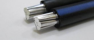
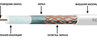
What are electrical cables made of?
The main conductor of electric current is aluminum or copper conductors. The larger their diameter, the higher the cable's capabilities.
Aluminum wires are cheaper, but they are more likely to deteriorate and have a lower electrical conductivity coefficient.
Copper cable is durable, does not break at bends and is capable of carrying more current than aluminum cable with the same diameter.
It is recommended that all wiring in the house be of the same type. This is due to the fact that to connect products from different materials, a special adapter will be required so as not to create a galvanic couple. In this case, oxidation and destruction of the wires occurs, which can lead to a short circuit.
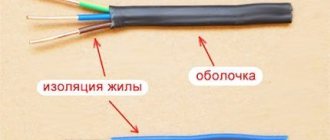
The main cores are covered in braids made of rubber, polyethylene or PVC. Often several of these insulated conductors are combined into a bundle, which in turn is covered with a protective sheath.
How to choose the right material
Copper is preferable to aluminum. It has greater conductivity and is less susceptible to corrosion. In addition, compared to copper, aluminum is fragile and can simply break if subjected to several bends. A negative property of aluminum is its rapid oxidation in case of contact with air, which results in the formation of a refractory oxide film on the surface. It conducts electricity poorly, which means it prevents the creation of good contact. A place with poor contact will heat up, spark, oxidize even more, heat up even more, and then it’s not far from a fire. And if you do not want to repeat the history of the “cat house”, you will have to periodically check the places where the aluminum conductors are attached to electrical appliances.
When fastened in screw clamps, aluminum exhibits another disadvantage - low yield strength. As a result, the aluminum slips out from under the clamp (“flows”), weakening the contact. Thus, aluminum wires located in junction boxes and other devices where clamps are used for connection also require periodic checking and tightening.
In addition, when aluminum comes into contact with copper, a galvanic couple is formed, in which the aluminum, subject to electrocorrosion, is destroyed. Which leads to further deterioration of the connection. We just talked about the results of this phenomenon.
What cross section is needed for 15 kW, how to choose?
In one of our articles, we examined in detail which machine is needed for 15 kW with a three-phase connection. Now it’s time to discuss what cross-section is needed for 15 kW, and how to choose the right cable.
The uninterrupted operation of all devices in your facility, as well as operational safety, depend on the cable cross-section. If you incorrectly calculate what cross-section is needed for 15 kW, the cable may overheat, which will lead to dire consequences.
For convenience, in our article we will also provide clear calculation diagrams that will help determine what cross-section is needed for 15 kW and for any other power.
How to choose SIP wire. The correct choice of self-supporting insulated wire
Self-supporting wires are the optimal solution for networks with both high and low voltage.
The popularity of this type of cable is associated with the ease of installation, convenience and safety of operation, and the minimum number of interruptions in the power supply due to emergencies.
Before choosing a SIP cable, you should decide for what purposes it is needed and under what conditions it will be used.
What types of wires are there?
Sip -1 and Sip -2 are used mainly for main power lines or their branches with a voltage of 0.6-1 kV;
Sip - 3 is also used for overhead lines, but is designed for much higher loads - 10 - 35 kV;
SIP-4 does not have a load-bearing conductor, it is laid mainly along the walls of buildings and structures, and its main area of use is branches from highways for supplying electricity to end consumers.
How to choose a section?
The cross-section of the wire must correspond as much as possible to the power of the connected load. Wires that are too thin will have a higher resistance and, accordingly, become very hot, which leads to significant energy losses during transmission, and can also cause insulation destruction, short circuits and even a fire.
How to choose the right one? Regulatory documents and tables indicating voltage and current for different types of self-supporting insulated insulated wires will help you select a cable with the characteristics required by the consumer.
The key characteristic for choosing a wire is the current strength that can pass through it.
This indicator is different for different sections:
- 16 mm2 - 100 A;
- 25 mm2 – 130 A;
- 35 mm2 - 160 A;
- 50 mm2 - 195 A;
- 70 mm2 - 240 A;
- 95 mm2 - 300 A;
- 120 mm2 - 340 A;
- 150 mm2 - 380 A;
- 185 mm2 - 436 A;
- 240 mm2 - 515 A;
Proportionally, as the cross-sectional area increases, the maximum permissible current strength for which this wire is designed for the load also changes. In addition, wires of different sections can withstand different intensities and durations of heating during operation.
If the task is to supply electricity to the house using a sip pipe, it is important to choose the right option. Typically, a wire with a minimum cross-section of 16 mm2 is more than enough
Cables with a smaller cross-section are simply not produced, and larger ones are not needed for household energy consumption.
In a standard household power supply network, there are no significant overloads, and the ambient temperature does not go beyond - 50 - + 60 degrees.
Selecting wire insulation
In addition to the characteristics of the current-carrying and load-bearing cores, it is worth paying attention to the insulation of the wires, or more precisely to the material of its manufacture. For regions with increased intensity of ultraviolet radiation, insulation made of light-stabilized polyethylene is recommended
If there is a risk of significant external heating during operation, it is worth giving preference to non-combustible insulation. If significant sudden changes in temperature are possible, or there is a risk of snow sticking or icing of wires, then in such conditions wires with thermoplastic insulation will be the most durable and work properly.
For regions with increased intensity of ultraviolet radiation, insulation made of light-stabilized polyethylene is recommended. If there is a risk of significant external heating during operation, it is worth giving preference to non-combustible insulation. If significant sudden changes in temperature are possible, or there is a risk of snow sticking or icing of wires, then in such conditions wires with thermoplastic insulation will be the most durable and work properly.
When operating in high humidity conditions, it is preferable to use sealed wires.
Production and sales
There are many cable manufacturers, and only the consumer can decide which wire to choose specifically from all the varieties. As for quality, it cannot be said that any of the large domestic or foreign manufacturers are significantly higher or lower in this indicator.
All requirements for SIP wires are presented in the relevant GOST, and if the products of a particular enterprise do not comply with it, they simply will not reach the market.
The manufacturer directly carries out mainly wholesale cable sales; for small volumes you will have to resort to the services of dealers or intermediaries. And decent companies are always ready to provide documentation confirming their cooperation with one or another manufacturer, as well as evidence of the quality of the product.
Choosing the right wire
Specialists from organizations that maintain power lines often, in order to save money or due to some personal preferences, use not the most suitable wires. These can be either insulated, but not intended for cable entry, or non-insulated, those that run as main lines along poles.
It is important to remember that if a bare wire was used to replace the input cable, then it should be laid securely and efficiently, because in strong winds such wires can short out. It may also happen that a truck enters the area and, while unloading, may touch the wires, which will lead to electric shock. However, someone may suggest making a replacement using insulated wire, but not intended for laying with air
In this case, due to constant sunlight, the insulation may crack and crumble over time, which is also unacceptable for an input cable
However, someone may suggest making a replacement using insulated wire, but not intended for laying with air. In this case, due to constant sunlight, the insulation may crack and crumble over time, which is also unacceptable for the input cable.
Based on the above, it is necessary to use a specially designed wire to lay the input to the house from the pole. SIP is ideal for such work because it is a self-supporting insulated conductor. It does not have the disadvantages that other wires have. We talked about how to connect a SIP wire to a house in a separate article.
Connection features
Modern electrical devices come in a wide range and are equipped with different functions. The connection to the power source is carried out according to a circuit diagram that allows you to connect the stove to a 220 V or 380 V network. The required power for a specific network is provided by installing special jumpers.
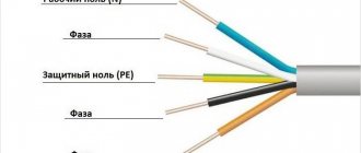
The distribution box on the back wall of the product has an image of such a diagram. The color of the core insulation helps to make proper connections.
A wire with black or brown insulation is connected to the phase contact, blue - to the zero contact, yellow-green - to the ground contact. According to the international designation, near such terminals there are respectively the letters L, N and the inverted designation of the letter T.
After connecting the wire or cable to the product being installed, all that remains is to connect it to the electrical panel. Now, using a tester, you need to check the correct connection. The work is considered complete and the product can be used if the manufacturer has equipped it with an outlet to connect the electric stove. And if it is not there, then you need to purchase a Euro plug with three pins for 25 ÷ 32 A and a PVS wire 3 x 2.5 in an amount of at least 2 m and make the necessary connecting device.
The correct connection is checked with a tester to ensure there is no short circuit. (short circuit) between each wire of the cable and on the plug in the absence of contact between ground and phase, while all switches on the product must be inoperative. The same check is carried out under different operating modes of the switches. Resistance readings from 4 to 10 ohms are considered normal when the mode is set to 100 ohms.
In any case, the block for connecting the power wire or cable contains six contact clamps and there is always a schematic diagram in the operating documents or on the stove itself, with the help of which you can, once you figure it out, connect the cable of the oven, electric stove or hob yourself if you have the necessary instrument and instrumentation (tester).
How to connect an electric stove is shown in detail in this video:
To protect a wire or cable, a differential circuit breaker or circuit breaker with characteristic C and an RCD is installed in an apartment or house panel.
Electric installation work
We will not dwell in more detail on the preparation of documentation for connecting the power supply; this is a separate topic. Our task is to determine the materials and devices for external installation work, which, although they are an intermediate stage in the connection, are the most important, since they are related to human safety.
Single-phase or three-phase input?
For both three-phase and single-phase networks, the permitted power is indicated in the technical specifications. This can be 15 kW for both options, that is, the benefit of a three-phase network is not in power, but in the possibility of using an input cable of a smaller cross-section and reducing the load, since the current is distributed over 3 phases. Therefore, in a three-phase network, the rating of the input circuit breaker will be lower.
But the input distribution board will be increased in size, since the meter itself is larger than a single-phase one, and the circuit breakers occupy 3-4 modules. Three-phase RCDs also have larger dimensions. This is a disadvantage of three-phase input into the house, but it is not very significant compared to such advantages as the ability to connect asynchronous electric drives, electric boilers, heaters, and electric stoves in the house.
To avoid phase imbalance from powerful electrical receivers, the electrician-installer must distribute the load as evenly as possible. The operating voltage of a three-phase network is 380V, therefore, in order to eliminate the risk of fire and electric shock, it would be a good idea to install a three-pole additional circuit breaker right before entering the house. This prevents short circuits at the input.
External connection and electrical panel
When connecting a private house to the power supply, an air input is most often used (which is also indicated in the technical specifications) with the installation of an electricity metering cabinet (SHUE) to eliminate cases of electricity theft and problems with the commercial registration of electricity supply.
According to the standards, the input cable must have a cross-section of at least 16 mm2 if the core is aluminum, and 10 mm2 if the core is copper, at a distance from the support pole of 25 m. For a distance of less than 25 m, the cross-section of the aluminum wire is 10 mm2, copper - 4 mm2 .
If you have decided on the method of connection from the pole to the house (aerial or underground), as well as the type and cross-section of the cable, then it remains to figure out exactly how the wire is connected to the house, from where further wiring to the devices is made.
The wire cross-section is selected according to the PUE based on the long-term permissible current. For aerial input, the most common cable is VVG or VVGng (modern version), as well as cable AVVG and SIP (self-supporting wire). By the way, for underground input, VBBbShv or AVBbShv cable is most often used. As you already understand, the presence or absence of the letter “A” means an aluminum core.
The value of the cable cross-section and the long-term permissible current for it are taken from the PUE. The optimal cross-sections for the input cable are 10, 16, 25 mm2, with a maximum permissible current, respectively: 50, 70, 85A (for underground input), and 80, 100, 140A for air input. For example, to a copper wire with a cross-section of 10 mm2, you can connect a power of 15 kW for a voltage of 230 V and from 30 kW for a voltage of 380 V.
If your main grounding bus is located on a pole and not in a cabinet, then the cable from the pole should be five-core (for example, VVG5 x 4.0) - three phases, a working zero (N) and a protective zero (PE).
High-quality cable products are produced domestically, Sevkabel, Concord, Nexans.
Installation of external electrical wiring
Any technical work related to construction is carried out in accordance with the developed project, which is carried out by specialists. To connect to the power grid, you must submit an application to the energy supply service that serves the building area. The document must indicate the optimal power and voltage required by the user.
The numbers can be calculated based on the total power of the estimated energy consumption of all electrical appliances. Based on this data, the relevant authorities issue a permit in accordance with the technical data, which describes the permissible power, voltage, wire cross-section, grounding rules, as well as protective and fixing equipment.
To connect a house to a 15 kW power grid, a voltage of 230-400 V is required, and the meter must have the appropriate machines.
Machine calculation parameters
Each circuit breaker primarily protects the wiring connected downstream of it. Basic calculations of these devices are carried out based on the rated load current. Power calculations are carried out in the case when the entire length of the wire is designed to carry the load, in accordance with the rated current.
The final choice of rated current for the machine depends on the cross-section of the wire. Only after this can the load value be calculated. The maximum current allowed for a wire with a certain cross-section must be greater than the rated current indicated on the machine. Thus, when choosing a protective device, the minimum wire cross-section present in the electrical network is used.
When consumers have a question about which machine should be installed at 15 kW, the table also takes into account the three-phase electrical network. There is a methodology for such calculations. In these cases, the rated power of a three-phase circuit breaker is determined as the sum of the powers of all electrical appliances planned to be connected through the circuit breaker.
For example, if the load of each of the three phases is 5 kW, then the operating current is determined by multiplying the sum of the powers of all phases by a factor of 1.52. Thus, it turns out 5x3x1.52 = 22.8 amperes. The rated current of the machine must exceed the operating current. In this regard, the most suitable protective device would be rated 25 A. The most common ratings of circuit breakers are 6, 10, 16, 20, 25, 32, 40, 50, 63, 80 and 100 amperes. At the same time, the compliance of the cable cores with the declared loads is clarified.
This technique can be used only in cases where the load is the same on all three phases. If one of the phases consumes more power than all the others, then the rating of the circuit breaker is calculated based on the power of this particular phase. In this case, only the maximum power value is used, multiplied by a factor of 4.55. These calculations allow you to select a machine not only according to the table, but also according to the most accurate data obtained.
When designing the electrical network of a new home, to connect new powerful devices, in the process of modernizing the electrical panel, it is necessary to select a circuit breaker for reliable electrical safety.
Some users are careless about this task, and can without hesitation connect any available machine, as long as it works, or when choosing, they are guided by the following criteria: cheaper, so that it won’t cost too much, or more powerful, so that it won’t break the bank again.
Very often, such negligence and ignorance of the basic rules for choosing the rating of a safety device leads to fatal consequences. This article will introduce the basic criteria for protecting electrical wiring from overload and short circuit, in order to be able to correctly select a circuit breaker according to the power consumption of electricity.
Common installation mistakes
Now let's pay attention to the main points during installation, which you can and should check during the work of an electrician. Firstly, the distance from the main support to the house should be no more than 25 meters
Otherwise, you will have to install additional support or make a pipe stand
Firstly, the distance from the main support to the house should be no more than 25 meters. Otherwise, you will have to install additional support or make a pipe stand.
You will also need a pipe stand if the energy supply organization does not give permission to install a metering cabinet on the facade and requires it to be placed on the nearest support.
Error No. 18 It is impossible for the clearance from the ground to the SIP wire on the facade of the house to be less than 2.5 m.
Don't be lazy, take a tape measure and check this height. If you cannot fulfill this requirement, install a gander.
Error No. 19 Do not attach the anchor bracket to the roof elements (windbreaker).
The load-bearing capacity of wood in these places is rather weak and fasteners can be torn out by the roots due to strong wind loads. Although the weight of the SIP is small, the lever, a couple of tens of meters long, does its job!
It is best to drill to the gable of the house using a good old traverse or supporting beam.
Error No. 20 It is also not recommended to attach SIP to the side wall of the building.
The point here is icicles, which in the spring often damage wires when they fall.
You can, of course, get confused and get rid of the icicles once and for all. But that's a completely different story.
The cable run to the switch cabinet must be protected with corrugation.
Error No. 21 The corrugation should not be gray as for home wiring, but resistant to ultraviolet radiation + non-flammable.
On wooden walls you need to use a metal hose.
Error No. 22 The end of the cable at the point of connection to the SIP on the facade should look down, not up.
This is protection against moisture penetration into the cut cable.
It’s even better to seal the end of the corrugation, where the wires come from, with a “TPI mini” glove from KVT.
It sticks perfectly to 25 and 32 corrugations.
If the cable goes directly into the attic, and does not go down the facade, then the entry through the wall must be made through a metal sleeve.
In this case, the tube should not be straight, but with the end bent towards the bottom.
The holes in it must be reliably sealed after inserting the cable. To protect the SIP itself from moisture, both on the support and on the facade, caps are used.
Error No. 23 If they are not there, then in a couple of years the wire, like a pump, will pick up water and very soon fail.
Here is a clear example confirming this problem.
https://youtube.com/watch?v=DWOP43hQ4zc%3F
The caps cost a penny, but without them long-term and reliable operation of the self-supporting wire is impossible. Almost every piercing clamp has such a cap in its design.
However, on some models they are attached to thin straps. It happens that the strap comes off and the cap is lost.
In this case, do not save money and be sure to buy yourself a new one. Fortunately, they are also sold separately.
Error No. 24 There is no need to remove the insulation from the cable core when connecting through a piercing clamp.
If your cable cross-section is too small (2.5mm2-4mm2, but where would such a cable go???), then the manufacturer recommends folding the core in half to ensure a larger contact area.
A thin vein can get between the spikes, and even if contact appears at first, over time this place will heat up and the cable will burn off. Cores from 6mm2 do not need to be folded in half.
The SIP itself from the support to the house, despite its insulation, must pass at least 0.5 m from the nearest trees and shrubs.
If you do not want to cut down your favorite birch or apple tree, then it is better to choose another attachment point on the facade. Any SIP passing through trees will eventually fray.
Mistake No. 25 Don’t listen to those who say that such wires can be safely run through green spaces and nothing will happen to them.
Even thick veins of 50-70 mm2 after a few years with constant winds are cut through by a branch like a hacksaw.
Here is a summary table of the minimum offsets and distances when laying SIP wires in a residential building.
https://youtube.com/watch?v=GYs2IU8b3_w%3F
Installing cables in the ground - 20 common mistakes. The formula for the ideal underground entrance to the house.
When installing an electrical input into a house, each of us thinks about how it is better to do it - overhead or underground?
Installation of air SIP is always much faster and several times cheaper.
Firstly, it is more reliable. And secondly, it does not spoil the facade of the building or the appearance of the surrounding area.
Often these two methods are combined. Initially, an input is made to a special pipe stand from a support.
And from this distribution cabinet the cable is laid in the ground and brought into the house. When the support is located not far from the building, some SIP wires are mounted directly on the facade.
But we will turn specifically to the underground input. Let's look at what difficulties you will encounter when laying cables in the ground and place special emphasis on common mistakes when performing this work, which ultimately, sooner or later, lead to failure of the cable line.
Cable installation in the ground can be done in two ways:
- without any protection (using armored KL grades)
- in pipes or special corrugation
Let's look at the first method first. Here, as a rule, a cable with tape armor is used - VBBbShv or AVBbShv.
It is not at all necessary to use armor of the type AABL, AAShV, where there is a one-piece cast protective shell made of aluminum. It could just be ribbons overlapping each other.
In this case, armor protects not so much from external influences (someone started digging where they shouldn’t), but from deformation and traction forces during soil heaving.
The same applies to the SIP wire. It cannot be laid in the ground, even in pipes.
You can often find videos on YouTube where copper CLs with 6mm2 conductors or 10mm2 aluminum are used. This is explained by the supposedly small number of electrical appliances in the house or country house.
In terms of load, this may be enough for you, but in terms of compliance with the requirements for the minimum cross-section of the PEN conductor, you will have a violation. For single-phase power supply, the cable must be three-wire, for three-phase power supply, it must be five-wire.
The selected cable should be carefully laid in the trench. What size should it be, what distances should be maintained when excavating it?
It is necessary to maintain a certain distance of 60cm.
Underground (trench) electricity input
Another way to introduce electricity into a wooden house is underground, through a trench.
Inputting electricity into a wooden house through a trench
In this case, the cable is lowered along a pole inside a steel pipe; its height must be at least 2 m from the ground level. Then, from the pillar to the entrance to the house, a trench is dug. Its depth:
- 0.7 meters, when laying the cable in a plastic or asbestos pipe or under the protection of a brick (concrete) slab
- 1 m - without protection.
The power cable also enters the house in a metal pipe. It can be passed through the foundation (strip), but not under it. The second option is to raise the pipe along the wall by at least 2 meters, and at this height pass it through the wall, also in a metal pipe.
Method of wiring electrical wiring through an external wooden wall
When connecting underground to a pole, it is recommended to use a power cable with copper conductors in reinforced insulation, preferably armored. With a power consumption of less than 15 kW, there are no restrictions on the cross-section of copper conductors, but most often they use a VBBShV cable with a conductor of 10 square millimeters.
All this work - right down to connecting power to the electric meter and sealing it - must be carried out by a special organization. Independent connection is prohibited, and even threatens with fines: an agreed project and a certain level of clearance are required. But you can choose the type of connection, and then do all the other work on installing electrical wiring in the house yourself.
Read how to assemble an electrical panel here. It will also be useful to read about the rules for connecting wires in junction boxes.
Cable for laying underground 15 kW
By using a cable for laying in the ground, you choose a reliable installation method. After all, the cable underground is protected from external influences (wind, frost, etc.), and also does not spoil the aesthetic appearance. However, laying cables in the ground is a rather labor-intensive process that requires compliance with the rules of PUE and PTEEP.
To lay a power cable in the ground, you need to carefully select the brand of cable. As a rule, the cable brand is selected based on the type of soil and its corrosiveness and the operating conditions of the cable. Corrosive activity depends on many factors, for example, the wetter and more acidic the soil, the higher the indicator. Here are some examples of ground cable brands and features for their installation. Operating conditions mean whether tensile loads will be applied to the cable. As a rule, I use armored cables for laying in the ground, since they do not require the use of additional protection during installation.
Cable for laying in the ground - review of power cable brands
The most common and frequently used brand of armored cable for laying in the ground is VBBbShv, according to the new standard (GOST R 53769–2010) VBShv or a similar aluminum cable AVBbShv. VBBShV cable is produced for voltages of 0.66 kV, 1 kV, 3 kV and 6 kV. Thanks to the armor made of steel strips in the design of this brand, cable laying is carried out without protective pipes. armor protects the cable from mechanical influences and rodents. In addition to laying cables in the ground, VBShv is used for laying by air, in special cable structures, damp places, etc. The peculiarity of the installation of VBBShV is that the steel armor must be grounded.
Other popular brands are armored cables for laying in the ground with paper insulation: copper SB, SBl, SKl, as well as aluminum cables with a similar design. In the design of paper-insulated cables, in addition to armor, there is always a metal sheath that protects the paper insulation from moisture. The sector shape of the cores of these cables significantly reduces the overall weight of the cable and saves space. The disadvantage of such cables is that if, when laid in the ground, the difference in the level of the route exceeds 15 meters, then a paper-insulated cable cannot be used. This is due to the viscous flowing impregnation of the paper insulation. in case of height difference, it is better to use cables with polyethylene insulation or cables with paper insulation with non-drip impregnation based on ceresin: TsSP, TsSB, TSKL, etc. Paper-insulated cables are most often designed for voltages of 1 kV, 6 kV and 10 kV.
An excellent replacement for paper-insulated cables are cables with cross-linked polyethylene (XPE) insulation. Popular brands of cable for laying in the ground: PvBbShv (produced at 0.66 kV and 1 kV), PvP, PvPg (10, 20, 35 kV). Despite the more expensive cost (by 5-60% depending on the voltage), cables with XLPE insulation have their advantages: the possibility of laying at subzero temperatures without additional heating, there are no restrictions on routes, etc.
Recommendations for installing cables for laying in the ground
- You do not have to use additional protection in the form of HDPE pipes if the cable in the ground is not subject to increased mechanical stress from pressure on the ground.
- The cable line in the ground should not intersect with other lines or utility networks, be located near trees, run under the foundation of a house, etc.
- The depth of the trench for the cable must be at least 0.8 = 0.9 m. The trench is cleared of debris, a sand cushion of approximately 10-12 cm is made in it
- The cable must be laid with a slack, wavy line and covered with sand, the soil poured on top is tightly compacted.
sells armored cables for laying in the ground of various brands and sections.
What documents need to be collected
To obtain permission to connect to electrical networks you will need:
- Application. The standard form can be filled out at the company or home serving the energy network by downloading the document on the Internet.
- List of machines and devices that consume energy.
- Copies of documents confirming your rights as the owner of the house or plot.
- Land plan showing electrical lines.
- Site or building plan.
- A copy of the passport of the owner of the plot or the person drawing up documents under a power of attorney.
- Power of attorney if the documents are not drawn up by the owner of the property.
The application must be completed in two copies. One copy signed by the employee accepting the documents remains in the hands of the owner of the house or an authorized representative.
The form must indicate:
- Full name of the person who is preparing the documents. This could be the owner of the site or a trusted representative.
- Passport issue date, series and number. Or details of an identity document.
- The address where the person applying is registered.
- Name of devices that consume energy.
- Device connection times. For example, during construction, energy consumption may differ from when the facility is put into operation.
- Power of connected devices.
- The name of the organization with which you agree to enter into an energy supply contract.
- Construction permit. This document is attached if there is nothing on the site yet.
The application can be submitted not only in person. It is possible to accept documents by mail. Send two copies of the completed form, the copies listed above, and a list of all documents in the letter.
The easiest and fastest way to send documents is the Internet. Register on the website of the organization servicing power lines, fill out the form and send copies.
The network company must report errors in the submitted documents within 6 days. If everything is fine, the applicant is sent two copies of the agreement with signatures in paper form. Technical conditions (TS) are attached to the contract. The contract and specifications are prepared within 15 days.
Once you receive the contract, you need to sign it and send it to the company. Or use an electronic signature by completing all documents on the organization’s website.
Entrust the solution to your problem to professionals!
Fast and profitable technological connection.
As a rule, the question of laying a cable at the appropriate power arises when preparing a facility for commissioning. In order to connect electricity to a facility, lay a cable and install a machine, it is not enough to obtain the appropriate power. And for this, in turn, you need to contact the network company and receive technical conditions, the composition of which will determine the total cost of the technological connection in your case.
- Even if you have already received not very favorable technical conditions, but have not yet signed an agreement, we can help you! Call us and we will get you good technical conditions that will allow you to reduce the final cost of the technological connection agreement several times!
- We will also carry out all the necessary electrical installation work for you quickly and efficiently. In our work we use only modern and reliable equipment, as well as high-quality consumables. Our specialists can easily navigate any situation and guarantee you the quality of all work performed. And we guarantee you the same price throughout the entire term of the contract!
- You can also use our assistance in concluding an agreement with a sales company. We will collect a complete package of documents for you, provide it to the guaranteeing electricity supplier and conclude a contract that is beneficial for you, once and for all solving the issue of non-contractual electricity consumption.
- We will speed up the final stage of putting the facility into operation: we will quickly obtain all the necessary approvals and permits!
vote
Article rating
Selecting the cable cross-section according to power
You can select the wire cross-section according to the power of the devices that will be connected. These devices are called load and the method can also be called “by load”. Its essence does not change from this.
The choice of cable cross-section depends on the power and current
Collecting data
First, find the power consumption in the passport data of household appliances and write it down on a piece of paper. If it’s easier, you can look at nameplates - metal plates or stickers attached to the body of equipment and equipment. There is basic information and, more often than not, power. The easiest way to identify it is by its units of measurement. If a product is manufactured in Russia, Belarus, or Ukraine, it is usually designated W or kW; on equipment from Europe, Asia or America, the English designation for watts is usually W, and the power consumption (this is what is needed) is designated by the abbreviation “TOT” or TOT MAX.
Example of a nameplate with basic technical information. There is something similar on any technology
If this source is also unavailable (the information has become lost, for example, or you are just planning to purchase equipment, but have not yet decided on the model), you can take the average statistical data. For convenience, they are summarized in a table.
Table of power consumption of various electrical appliances
Find the equipment you plan to install and write down the power. Sometimes it is given with a wide spread, so sometimes it is difficult to understand which figure to take. In this case, it is better to take the maximum. As a result, when calculating, you will slightly overestimate the power of the equipment and will need a cable with a larger cross-section. But for calculating the cable cross-section it is good. Only cables with a smaller cross-section than necessary will burn. Routes with a large cross-section work for a long time, as they heat up less.
The essence of the method
To select the wire cross-section for the load, add up the power of the devices that will be connected to this conductor
It is important that all powers are expressed in the same units of measurement - either in watts (W) or in kilowatts (kW). If there are different values, we bring them to a single result. To convert, kilowatts are multiplied by 1000 to get watts
For example, let's convert 1.5 kW into watts. This will be 1.5 kW * 1000 = 1500 W
To convert, kilowatts are multiplied by 1000 to get watts. For example, let's convert 1.5 kW into watts. This will be 1.5 kW * 1000 = 1500 W.
If necessary, you can carry out the reverse conversion - convert watts to kilowatts. To do this, divide the figure in watts by 1000 to get kW. For example, 500 W / 1000 = 0.5 kW.
Next, the selection of the cable cross-section actually begins. It's very simple - we use a table.
| Cable cross-section, mm2 | Conductor diameter, mm | Copper wire | Aluminum wire | ||||
| Current, A | power, kWt | Current, A | power, kWt | ||||
| 220 V | 380 V | 220 V | 380 V | ||||
| 0.5 mm2 | 0.80 mm | 6 A | 1.3 kW | 2.3 kW | |||
| 0.75 mm2 | 0.98 mm | 10 A | 2.2 kW | 3.8 kW | |||
| 1.0 mm2 | 1.13 mm | 14 A | 3.1 kW | 5.3 kW | |||
| 1.5 mm2 | 1.38 mm | 15 A | 3.3 kW | 5.7 kW | 10 A | 2.2 kW | 3.8 kW |
| 2.0 mm2 | 1.60 mm | 19 A | 4.2 kW | 7.2 kW | 14 A | 3.1 kW | 5.3 kW |
| 2.5 mm2 | 1.78 mm | 21 A | 4.6 kW | 8.0 kW | 16 A | 3.5 kW | 6.1 kW |
| 4.0 mm2 | 2.26 mm | 27 A | 5.9 kW | 10.3 kW | 21 A | 4.6 kW | 8.0 kW |
| 6.0 mm2 | 2.76 mm | 34 A | 7.5 kW | 12.9 kW | 26 A | 5.7 kW | 9.9 kW |
| 10.0 mm2 | 3.57 mm | 50 A | 11.0 kW | 19.0 kW | 38 A | 8.4 kW | 14.4 kW |
| 16.0 mm2 | 4.51 mm | 80 A | 17.6 kW | 30.4 kW | 55 A | 12.1 kW | 20.9 kW |
| 25.0 mm2 | 5.64 mm | 100 A | 22.0 kW | 38.0 kW | 65 A | 14.3 kW | 24.7 kW |
To find the required cable cross-section in the corresponding column - 220 V or 380 V - we find a figure that is equal to or slightly greater than the power we previously calculated. We select the column based on how many phases are in your network. Single-phase - 220 V, three-phase 380 V.
In the found line, look at the value in the first column. This will be the required cable cross-section for a given load (power consumption of devices). You will need to look for a cable with cores of this cross-section.
A little about whether to use copper wire or aluminum. In most cases, when laying wiring in a house or apartment, cables with copper conductors are used. Such cables are more expensive than aluminum ones, but they are more flexible, have a smaller cross-section, and are easier to work with. But copper cables with a large cross-section are no more flexible than aluminum ones. And under heavy loads - at the entrance to a house or apartment with a large planned power (from 10 kW or more), it is more advisable to use a cable with aluminum conductors - you can save a little.
How many kilowatts will SIP withstand?
While browsing the internet for electrical installations, I found a thread on one forum discussing “whether a 4x16 sip can withstand 15 kW.” The question arises because 15 kW 380 volts are allocated for connecting a private house. Well, people are wondering if it’s not enough to lay 16 square meters on a branch from the overhead line? I first looked into the PUE, but for some reason I didn’t find anything there on the topic of SIP power.
There is only plate 1.3.29 “Permissible long-term current for non-insulated wires according to GOST 839-80.” And it shows that the maximum permissible current for the cross section is 16 kV. mm. wire type AC, ASKS, ASK outdoors is 111 amperes. Well, at least something to start with.
How many kilowatts can a 4x16 SIP withstand?
But there is GOST 31943-2012 “Self-supporting insulated and protected wires for overhead power lines.” At the end of the standard, in paragraph 10 of the operating instructions, there is a sign
How many kilowatts can SIP withstand - table:
| SIP 4x16 | 62 kW | 22 kW |
| SIP 4x25 | 80 kW | 29 kW |
| SIP 4x35 | 99 kW | 35 kW |
| SIP 4x50 | 121 kW | 43 kW |
| SIP 4x70 | 149 kW | 53 kW |
| SIP 4x95 | 186 kW | 66 kW |
| SIP 4x120 | 211 kW | 75 kW |
| SIP 4x150 | 236 kW | 84 kW |
| SIP 4x185 | 270 kW | 96 kW |
| SIP 4x240 | 320 kW | 113 kW |
Calculation method (update from 02/19/2018)
We take plate 10 and from it we find that one core is 16 sq. mm. withstands - 100 amperes. Next, we take the following calculation formulas:
for single-phase load 220V P=U*I
for three-phase load 380V P=(I1+I2+I3)\3*cos φ*1.732*0.38
update from 02/19/2018 Regarding the calculation of power for a three-phase load, you need to understand that a lot depends on the type of consumers (more precisely, what kind of load they provide active or reactive, it depends on what cos φ should be substituted into the formula, in this case for calculations it is equal to 0.95 )
Dear visitors to the site, I might not have noticed your caustic but technically correct comments on the article if just today a person called me with the question: “what kind of sip do I need for 120 kW?” According to the sign, a SIP with a cross section of 50 mm square would be perfect for him. Even if we omit the fact that the length of the line affects the voltage drop (it has 150 meters), we should not forget that the load on the phases can vary, as can be seen from the formula - it takes the average value for three phases. Here you just need to understand that the phase current can exceed the maximum permissible values for a given wire cross-section.
Therefore, if the value of the load you need is closer than 10% to the table, you should choose a larger section of the vulture from the list. Let me explain with the example of 120 kW. According to the table, for this three-phase load, a SIP with a conductor cross-section of 50 mm is suitable, but this is less than 10%. That is, 121 kW * 0.9 = 109 kW. Accordingly, you need to choose SIP 3x70+1x54.6.
At the beginning of the topic, the question was raised: “will a 4x16 15kW sip handle it?” Therefore, for a private house we multiply 220Vx100A = 22 kW per phase. But don’t forget that we have three phases. And this is already 66 kilowatts in total for a residential building. Which is a 4-fold margin relative to the issued technical conditions.