Your home and LED lamps
Advantages
- Low energy consumption. LED overhead lamps consume ten times less than incandescent lamps and three times less than fluorescent models. This makes it possible to save money on electricity.
- Service life is one hundred thousand hours. Or this can be translated into 11 years of continuous service. Therefore, they practically do not require replacement.
- Does not contain mercury. Which is an environmentally friendly product.
Another advantage is that LED overhead lights are easy to install. They can be installed in any type of ceiling, which cannot be done with built-in models. They can only be done during global repairs.
Negative points
As with any other thing, there is a downside to LED surface-mounted lights.
- High price. The main disadvantage. LED lamps are 6-8 times more expensive than fluorescent models.
- "Degradation". If the model has a budget price, then after 3-5 years the lighting intensity drops. Given that the payback for using this lamp model will pay off only after five years, the disadvantage is significant.
Based on all this, we can conclude that the advantages and disadvantages of these lamps are on equal scales. Therefore, when making a choice, clearly weigh the pros and cons.
Halogen chandeliers, including those with remote controls
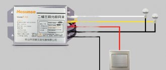
Halogen light bulbs are designed for a voltage of 12 V, so 220/12 V voltage converters are installed in such chandeliers. As a rule, the control circuit is assembled and only 2 wires can stick out of the chandelier, even if the chandelier is controlled by a remote control.
These two conductors are connected to the electrical wires in any order, although the terminal block may be marked with the letters "N" and "L". In addition, there may also be a grounding conductor.
The following video shows how to connect a chandelier with a remote control.
Connecting a chandelier with halogen lamps
Watch this video on YouTube
Popular faults
During operation of the chandelier, which is controlled using a remote control, various malfunctions may occur, in particular:
- For combined chandeliers, one of the groups of lamps - LED or halogen - does not turn on.
- The electronic switch for the chandelier has failed.
- It is impossible to turn on the lighting device using the remote control.
- There is no way to turn on the chandelier.
Each of the listed options may be affected by several causes of failure. Based on this, as described above, you will need to find the source of the malfunction, and then only begin repairs. A multimeter will help to identify failed elements installed in the chandelier.
The chandelier does not turn on when using the remote control
Causes of malfunction and their elimination:
- You need to make sure that the battery in the remote control is working properly. This can be done using a multimeter or a regular tester. If the battery is bad, you should replace it with a new one and recheck the functionality of the remote control.
- If after such actions the remote control still does not work, you need to check the functionality of its buttons through the phone camera. When you press the buttons, a white spot will be visible on the phone screen. If the buttons do not work, you can try to repair them or partially replace them. If repair is impossible, you will have to buy a new remote control, but there is a catch - it comes with a receiver. Replacing it is quite a labor-intensive task.
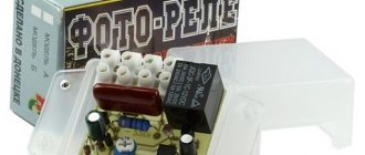
The connection diagram is indicated on the electronic transformer itself
- After checking the batteries and buttons on the remote control and making sure that everything is working properly, you should check the signal receiver. If the breakdown lies in it, then you will need to purchase it, but in this case you will also have to buy a remote control.
Buttons most often fail due to clogging of their contacts. You can fix this little thing as follows:
- It is necessary to thoroughly wipe the microcircuit contacts from dirt, lightly clean them and remove the factory grease. Now you need to prepare the powdered graphite. Apply super glue to the contacts and sprinkle with powder. After this you can assemble the remote control.
- If graphite is not available, you can use foil that does not allow electric current to pass through.
If the radio signal receiver malfunctions, you will need to purchase a new remote control, as well as a control unit, which are tuned to the same frequency. Usually the kit includes a connection diagram and repairing a chandelier with a control panel, according to it, becomes simple. You just need to follow the recommendations in the instructions provided.
Actions for partially non-functioning lamps in a chandelier
How to repair a chandelier with a remote control in this case? The procedure for repair work will be radically different and look like this:
- If halogen lamps burn out, you will need to turn off the power to the lamp and replace the unusable lamps.
- If the LED backlight does not turn on, it means that at least one LED has failed. In this case, it would be optimal to replace the entire tape.
- During normal operation of halogen lamps and LED strips, you need to check the integrity of the transformer. To do this, you will need to remove the wires connected to it and use a multimeter to measure the presence of voltage at the terminals. If defective, replace with a similar model.
Light bulbs shine when the lamp is moved
The chandelier does not light up using the remote control and wall switch, but when you move the light fixture with your hand, the lamps flicker occasionally. The fact is that there is a weak contact in the place where the chandelier wires connect to the power cable. This can happen if the chandelier with remote control was connected by an inexperienced electrician and did it carelessly, or if poor-quality terminal blocks were installed. It's easy to fix. You will need to remove power from the chandelier, clean all contacts and reconnect.
The chandelier doesn't work at all
After this situation occurs, you must do the following:
- It is necessary to measure the presence of voltage in the supply network. To do this you will need a voltmeter, multimeter or a regular contact.
- If there is power, you should make sure that the lamps themselves are working properly. Non-working ones should be replaced with new ones.
- It is necessary to check for a short circuit between the phase and neutral wires or elements inside the chandelier.
Quite high quality chandeliers with remote control that
Connecting a chandelier with a remote control and reviewing possible troubles
The development of technology has led to the use of modern lighting systems in domestic premises, apartments and private houses.
The use of LED chandeliers with remote control is increasingly becoming fashionable and practical. Stadiums, concert halls and other rooms and areas with large sizes and ceilings, where the light needs to be controlled remotely, are in great need of equipping this kind of lighting. Installing an LED chandelier allows you to turn on or off the light while in bed, after which you will not need to walk in the dark. But, like all equipment, sometimes such equipment requires repair. Content
Device and connection diagram
If malfunctions occur with such lighting sources, it is necessary not only to be able to repair them, but also to begin identifying them. The connection diagram of the chandelier and its structure is what you need to know to successfully identify a breakdown. Inside this electrical equipment there may be many cords and parts, depending on which not every electrician will undertake to repair it.
Chandelier with remote control
There are three types of chandeliers controlled by remote control, which come with the following types of light bulbs:
- halogen lamps;
- incandescent lamps;
- LED bulbs.
In addition to the above types, there are lighting devices with a combined type remote control. These lighting devices have the most complex design, combining halogen and LED lamps. The inclusion of such lighting devices can be performed by individual elements or completely by all groups for lighting.
There are many types and models of radio-controlled light sources, but their filling, in most cases, is assembled from monotonous modules, which include the following:
- lamp control unit (controller to which the remote control is attached);
- a block consisting of halogen lamps;
- block consisting of LED lamps.
In order to avoid mistakes when repairing a chandelier with a control panel yourself, you need to find out the detailed purpose of each block separately from each other.
Controller unit for chandelier
The controller acts as a remote switch. It is controlled by a remote control or a switch located on the wall. In electrical engineering, the controller unit is called a “switch” (switch). This device is responsible for the reliable operation and proper functioning of all elements and modes of the chandelier.
For such lamps, radio-controlled Wireless Switch units are usually used, which come in various types and parameters. The most common controllers are Y-2E and Y-7E. Let's look at the parameters of the controller marked Y-7E:
- supply voltage ranges from 200 to 240 V;
- output channels – 3 pcs.;
- power of one channel – no more than 1 kW when using halogen and incandescent lamps;
- power of one channel - no more than 0.2 kW, if energy-saving lamps are used;
- The remote control is capable of giving commands at a distance of 8 meters.
Each controller that performs remote control of the chandelier has a circuit for connecting this device. There are standard markings on these management charts. The letter K denotes the switches through which voltage is supplied to power the controller. This schematic instruction provides for connecting the Red wire (red wire) to the L - phase, and the Black wire (black wire) to the N - zero. The number of wires depends on the number of light bulbs, which are divided into groups. This controllable module has a white antenna that is needed to receive the signal, and it does not connect anywhere.
In addition to three-channel radio-controlled units, there are one-, two- and four-channel controllers. Their type allows you to connect the appropriate number of groups.
Unit containing halogen lamps
This unit consists of an electronic transformer, which is a power supply for halogen lamps, as well as halogen lamps. Transformers are used from various manufacturers and parameters. This depends on the power consumption of the lighting fixture. It can be 105 W, 160 W, etc. Installing more powerful lamps than those for which the electronic transformer is designed will result in its failure or melting due to the temperature of the sockets.
To power the transformer, two wires are used - red and brown. There are also two wires coming out of it - white and gray, to which you need to connect the halogens. The number of electrical transformers will coincide with the number of outputs on the controller and the groups of lamps used.
LED block
Such a block is installed if there is an LED group of lamps in the lighting device and is connected to one of the controller outputs using a driver. If the chandelier is Chinese, it may have a driver installed with unknown characteristics that were not indicated on the body. Typically, its connection is made with two incoming red wires (phase and zero), and there are also two output wires - the black one is connected to the “+” of the LEDs, and the white one is connected to the “-”. The LEDs in the chandelier are connected in series, and if one of them breaks, the entire chain will stop functioning.
Installing new elements in a chandelier with LEDs is quite simple. To do this, you will need to install a new one in place of the old element in the same connector, while observing its polarity.
If the LED breaks down, you can use a temporary solution to the problem. To do this, you need to replace it with a wire jumper. The characteristics of the driver allow it to work without missing LEDs, however, such long-term use will lead to a significant reduction in the service life of the remaining elements.
How to connect a chandelier with a remote control?
Before connecting the chandelier, it is necessary to install the mounting rail to the ceiling. Now you need to remove the power from the supplied cable in the ceiling and find the phase wire. A lighting control unit and a three-contact terminal are installed on top of the luminaires, but in houses without grounding the grounding contact is not used.
The next step is to connect the phase and neutral wires of the power cable to the corresponding terminals. Usually the controller wires are already connected according to the attached diagram. After this, the chandelier is fixed on the bar, lampshades are installed and light bulbs are screwed in. Now you can apply voltage and check that the connection is correct.
Popular faults
During operation of the chandelier, which is controlled using a remote control, various malfunctions may occur, in particular:
- For combined chandeliers, one of the groups of lamps - LED or halogen - does not turn on.
- The electronic switch for the chandelier has failed.
- It is impossible to turn on the lighting device using the remote control.
- There is no way to turn on the chandelier.
Each of the listed options may be affected by several causes of failure. Based on this, as described above, you will need to find the source of the malfunction, and then only begin repairs. A multimeter will help to identify failed elements installed in the chandelier.
The chandelier does not turn on when using the remote control
Causes of malfunction and their elimination:
- You need to make sure that the battery in the remote control is working properly. This can be done using a multimeter or a regular tester. If the battery is bad, you should replace it with a new one and recheck the functionality of the remote control.
- If after such actions the remote control still does not work, you need to check the functionality of its buttons through the phone camera. When you press the buttons, a white spot will be visible on the phone screen. If the buttons do not work, you can try to repair them or partially replace them. If repair is impossible, you will have to buy a new remote control, but there is a catch - it comes with a receiver. Replacing it is quite a labor-intensive task.
- After checking the batteries and buttons on the remote control and making sure that everything is working properly, you should check the signal receiver. If the breakdown lies in it, then you will need to purchase it, but in this case you will also have to buy a remote control.
- It is necessary to thoroughly wipe the microcircuit contacts from dirt, lightly clean them and remove the factory grease. Now you need to prepare the powdered graphite. Apply super glue to the contacts and sprinkle with powder. After this you can assemble the remote control.
- If graphite is not available, you can use foil that does not allow electric current to pass through.
If the radio signal receiver malfunctions, you will need to purchase a new remote control, as well as a control unit, which are tuned to the same frequency. Usually the kit includes a connection diagram and repairing a chandelier with a control panel, according to it, becomes simple. You just need to follow the recommendations in the instructions provided.
Top view of chandelier with remote control
If it is not possible to replace the necessary parts, you can use another method, but the chandelier will not be controlled remotely. In this case, the assembly of the chandelier with the remote control will be carried out by removing the unusable receiver, and the controller will be connected directly to the two-key switch. One key will be responsible for changing the set modes, and the second for switching backlight modes.
Actions for partially non-functioning lamps in a chandelier
How to repair a chandelier with a remote control in this case? The procedure for repair work will be radically different and look like this:
- If halogen lamps burn out, you will need to turn off the power to the lamp and replace the unusable lamps.
- If the LED backlight does not turn on, it means that at least one LED has failed. In this case, it would be optimal to replace the entire tape.
- During normal operation of halogen lamps and LED strips, you need to check the integrity of the transformer. To do this, you will need to remove the wires connected to it and use a multimeter to measure the presence of voltage at the terminals. If defective, replace with a similar model.
To avoid quickly burning out halogen lamps, do not touch them with bare hands.
Light bulbs shine when the lamp is moved
The chandelier does not light up using the remote control and wall switch, but when you move the light fixture with your hand, the lamps flicker occasionally. The fact is that there is a weak contact in the place where the chandelier wires connect to the power cable. This can happen if the chandelier with remote control was connected by an inexperienced electrician and did it carelessly, or if poor-quality terminal blocks were installed. It's easy to fix. You will need to remove power from the chandelier, clean all contacts and reconnect.
The chandelier doesn't work at all
After this situation occurs, you must do the following:
- It is necessary to measure the presence of voltage in the supply network. To do this you will need a voltmeter, multimeter or a regular contact.
- If there is power, you should make sure that the lamps themselves are working properly. Non-working ones should be replaced with new ones.
- It is necessary to check for a short circuit between the phase and neutral wires or elements inside the chandelier.
Quite high quality chandeliers with remote control that
Connecting the wires of the lighting fixture with the power cable
found on the domestic market, produced by Garlen. The manufacturer of lighting fixtures Garlen is in great demand among customers.
Installation of a chandelier with remote control
The most important question is why does a chandelier need a remote control if there is a switch? And is a switch necessary at all if there is a remote control? In this part of the article I will answer these questions.
The remote control is needed to remotely switch different operating modes of the chandelier. As a rule, in a chandelier, which is controlled from a remote control, there are several light groups - 2 or 3 groups of LED lighting, to create various lighting effects, and 1 or 2 groups of halogen light bulbs, actually for lighting.
Each group is powered through its own power supply (adapter, or electronic transformer), with the exception of those rare cases when 220V light bulbs are used.
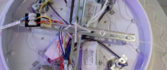
The photo shows the devices that make up the chandelier circuit:
How does an LED chandelier work?
The remote control is carried out via a radio channel. This means that it is not at all necessary to point the remote control directly at the chandelier, as we do when controlling a TV. The radio channel consists of a receiver (controller) and a transmitter (remote control).
The range of such a remote control can be different, it all depends on the needs of the client. For example, for a small chandelier in a standard apartment, a control panel with a range of up to 10m is suitable, and for chandeliers used in public places, remote controls with a range of 100m are used.
The remote control is always used in conjunction with a receiver; they are tuned to the same frequency. And they are sold as one set. The receiver supplies power to the controller, which creates light and color effects by outputting various signals to the LEDs. LEDs, as a rule, are used in different colors, and together with glitter and glass (or even crystal) they create very beautiful light and color effects.
Typically, the receiver and controller are located in the same housing and may be called a remote switch, wireless control panel, etc.
The minimum number of groups of such a switch is one; two- or three-channel ones are more common. I have never seen more than three channels.
Effects are switched by pressing buttons on the remote control.
What about the switch? Firstly, it is needed for its main task - turning off the chandelier. In other words, power is supplied to the chandelier through it, and sometimes it is much more convenient to turn off the chandelier with a switch than with the remote control, which still needs to be found and picked up.
In addition, the controllers make it so that every time you turn on (supply power) a new lighting effect is turned on. So, the switch is also a light mode switch. And in principle, even if the remote control is lost or the batteries are dead, the chandelier can be controlled quite well.
In addition to the controller with the receiver, the chandelier body contains electronic transformers and power supplies for LED and halogen lamps.
Everything will be shown below in the photo.
Enough theory, let's move on to practice.
Installation and repair of a radio-controlled chandelier
Here I will talk about the design and malfunctions of radio-controlled chandeliers with halogen and LED light sources.
Despite all their diversity, almost all chandeliers with a control panel have a modular design and are assembled from the same type of electronic components.
Here are the main ones:
Radio-controlled relay and control panel;
Lamp with halogen lamps.
Depending on the design, chandeliers can be either pure LED or combined with halogen lamps. Thanks to the radio-controlled relay, you can turn on either all the lamps, or only the LED or halogen part.
Where to buy parts and ready-made blocks for repairing a chandelier with a remote control?
Hereinafter I will refer to the well-known online store AliExpress. It is there that you can find all the necessary spare parts and units, which will be discussed further. My choice is due to the fact that there is a large selection and low prices.
In radio markets, as well as in electrical goods stores, similar products are more expensive - their prices are simply “inflated”, although the quality is the same. Therefore, for those who know how to buy on the Internet, I advise you to pay attention to this. The only disadvantage of such purchases is the rather long delivery (1-2 months), although this largely depends on the seller. I have already talked about how to search and order goods on Aliexpress here.
Radio controlled relay.
The radio control of the chandelier is organized using a radio relay, which is designed to be powered from a 220V power supply. Depending on the “steepness” of this block, it can contain from 2 or more electromagnetic relays, which are designed to switch a load with a power somewhere up to 1 kW.
This is what this block looks like. It is he who receives commands from the wireless remote control and turns on a certain section of the chandelier (halogen or LED lamp, or both). Pay attention to the inscriptions and typical connection diagram, which is shown on the unit body.
Here's what's inside this box.
Hidden under the green YDK-30 RF module is the HS153SP-J . The two black things that take up a third of the printed circuit board are electromagnetic relays.
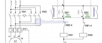
Here is a schematic diagram of a radio relay for 2 control channels, model Y-2E .
The diagram is drawn by hand, so there may be errors. Similar radio-controlled relays powered by a 220-volt power supply also have the same circuitry.
A radio module is installed on the printed circuit board (labeled YDK-30 ). It is made on SMD elements and, apparently, has a fairly simple circuit design.
The radio receiver circuit is powered using a “quenching” capacitor circuit. Excess mains voltage is suppressed by ballast capacitor C2. This implementation of the circuit is simple, but very dangerous, since there is no galvanic isolation from the power supply. Voltage stabilization is implemented using zener diodes VD5, VD6 ( 1N4741A ) at 11 volts.
In addition, over time, many encounter incorrect operation of the radio relay. And it is connected precisely to the ballast capacitor C2.
Here is a message from one of the site visitors who encountered this problem and discovered its cause:
“These radio modules have a typical breakdown - after some time of operation (2-3 years), only 1 channel works normally, when you turn on the 2nd or 3rd remote control it stops responding to button presses, that is, you can turn on all channels, but after that it cannot be controlled only with a switch on the wall or by bringing the remote control closer than 0.5 meters to the chandelier.
This is due to the degradation of the film capacitor in the radio relay power supply. In the photo it is indicated by a red arrow.
The capacity of this capacitor is usually 1-1.5 µF, the operating voltage is not lower than 250 volts (marking: 105j250v , which means 10 * 10 5 picofarads or 1 µF). Replace with similar domestic or imported ones with a capacity NOT greater than that of the one you have installed (more is possible, but there is a high probability that the zener diode will either heat up wildly or burn out immediately."
Despite the good appearance of the radio relay, it sometimes causes the halogen part of the lamp to not work. The fact is that the place where the electromagnetic relay is soldered onto the printed circuit board degrades over time. Either because of poor soldering, or because of the high inrush current that is generated when the halogen lamp is turned on.
Wireless chandelier control panel.
The RF control panel is also quite simple. The printed circuit board has 2 transistors ( S8550 and S9018 CS5211AGP encoder chip . It encodes commands and transmits them to the sending node.
The buttons are designed in the same way as standard remote controls - there are no mechanical buttons, like tactile buttons.
Since the chandelier is assembled from blocks, the radio-controlled relay can be easily replaced. You can look for a new unit at an electrical goods store or order it online. Here is the link.
The relay block can have several control channels. For example, one includes the halogen part of the chandelier, the other includes an LED lamp. In this case, the radio-controlled relay has 2 control channels (2 way). If you need a relay with a large number of control channels, then take the one that is required. Here you can select a module for 1, 2, 3 or 4 control channels.
In some cases, the radio-controlled relay unit can be completely disabled. This may be necessary when the unit itself is faulty and a suitable one is not available.
In this case, you can completely “throw out” the unit and turn on the chandelier using a regular power switch.
If you wish, you can assemble a chandelier with a control panel from an ordinary one. Or make the background lighting of the room, the main room and, for example, a street spotlight controllable from the remote control. To do this, you will need the same radio-controlled relay unit or, in other words, a controller with a remote control. At one time, at a wholesale store, I bought this ELEKTROSTANDARD unit for 3 channels (3 way).
This is the same set of wireless relays with a remote control only in blister packaging.
The set includes a remote control with a holder, a 12V battery for the remote control, and the unit itself has 3 channels. It is written that the remote control range is 8 meters. Each control channel is designed to connect a load up to 1 kW. For all channels, a total of 3 kW.
The hardware itself was allegedly developed in Germany and assembled in China. In fact, its electronic filling is no different from the filling of those blocks that are widely used in Chinese chandeliers with a remote control. Only detailed inscriptions are in Russian, but everything is the same.
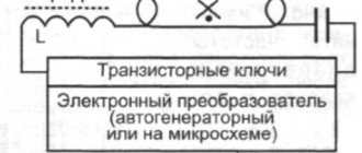
Halogen lamp.
To power halogen lamps (usually type G4), which are designed for a voltage of 12V and a power of 20W (watt) each, step-down pulse converters are used, which are called an electronic transformer. This is what he looks like.
The insides of an electronic transformer.
Halogen light bulbs can be easily checked with a multimeter by measuring the resistance of the filament. Attention! Halogen bulbs should not be touched with your fingers! Only through a napkin or rag material.
In the particular chandelier that fell into my hands, for each electronic transformer there were 5 halogen lamps, each with a power of 20W. Halogen lamps are connected in parallel . In total, one electronic transformer supplies 100 watts of power to the lamps.
Sometimes the electronic transformer in the chandelier fails. In this case, the part of the chandelier where the halogen bulbs are installed will not shine when turned on. In this case, you can replace the faulty electronic transformer. At the same time, it is worth first checking the serviceability of the radio relay itself, since it is through it that the mains voltage (220V) is supplied to the input of the electronic transformer.
LED chandelier controller circuit
Let me remind you that this remote radio-controlled switch (control unit) can be used not only in chandeliers, but also in other electronic devices. You can switch any voltage (within reasonable limits, with a little modification of the printed circuit board), and any currents (the current is limited by the relay current, but additional ones can be installed).
The controller diagram is shown below:
Controller circuit for chandelier with control panel Sneha B-827
The diagram was taken by me from the site www.tokes.ru, thank you!
Having this diagram, you can safely take on repairing the controller, and the chances of success are quite high.
To examine the diagram in detail, I enlarged it and divided it into 6 conventional parts:
Let's look at each part separately.
Repair of a chandelier controller with remote control
Such a controller is also called in everyday life a remote control, a radio control unit, or a remote switch.
Where the chandelier control unit is mainly used and how it works, I described in great detail in my other articles:
- , . . LED driver repair and circuit.
- , , (twilight relay).
That's it, enough introduction. Let's move directly to the topic of the article.
How does a controller with a remote control for a chandelier work?
Briefly once again what we are talking about.
The whole system looks like this:
We will not consider where the controller wires are connected in this article. This has been given a lot of attention in my other articles, links above.
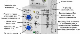
Instructions for using and connecting the control unit are given on its body:
Instructions for controlling and connecting the LED chandelier controller
We open the housing of the remote switch. Digital Remote Switch
In the photo, I specifically placed the remote control and controller next to each other so that the name could be seen.
LED chandelier controller circuit
Let me remind you that this remote radio-controlled switch (control unit) can be used not only in chandeliers, but also in other electronic devices. You can switch any voltage (within reasonable limits, with a little modification of the printed circuit board), and any currents (the current is limited by the relay current, but additional contactors can be installed).
The controller diagram is shown below:
Controller circuit for chandelier with control panel Sneha B-827
Having this diagram, you can safely take on repairing the controller, and the chances of success are quite high.
To examine the diagram in detail, I enlarged it and divided it into 6 conventional parts:
LED chandelier controller circuit broken down into parts for easy understanding
Let's look at each part separately.
Power supply and switching
This part of the circuit includes input and output circuits, and relay contacts through which the load is powered.
The relay coils are included in the 3rd part of the circuit.
Zero and phase come next.
This part receives 220V voltage, zero and phase. Zero passes to the diode bridge through a choke, which to some extent eliminates high-frequency power supply noise, which can lead to failures. Capacitor C1 serves the same purpose.
The phase to the diode bridge comes through the quenching capacitor C2, which is shunted by resistor R1 for safe operation.
Each diode of the diode bridge is also shunted by a capacitor to minimize the high-frequency component of the supply voltage.
The output of the diode bridge is loaded onto filter capacitors C3 and C4, which serve to filter the low-frequency and high-frequency components of the bridge output voltage. The voltage is stabilized by a chain of series-connected 12V zener diode VD2 and limiting resistor R4.
As a result, at point A a DC voltage of 12.5-15V is generated in relation to the neutral wire (minus the diode bridge).
Key transistors
Next, the 12V voltage is supplied to the +5V power stabilization circuit. The voltage at the input of this stabilizer is reduced and stabilized by a chain of resistor R6 and a 12V zener diode VD4 and supplied to the 78L05 integrated stabilizer. Further, the stabilized +5V voltage is additionally filtered by capacitors C5 and C6, since a special quality of constant voltage is required.
Radio module
Radio decoder
The controller we repair
The circuit of this controller almost completely coincides with the circuit given above. The only difference is that this controller has not 2 channels, but 3. But the principle is absolutely the same. Let's take a little time to get acquainted with some of the internals and differences from the above diagram.
This is what a controller for controlling a 3-channel chandelier looks like from the inside:
Appearance of the controller circuit
Closer view of the controller circuit
Three relays (black, left) correspond to three control channels.
To the right of the top relay we see a row of black semicircular parts. These are three key transistors and a +5V stabilizer. Here's what it looks like from a different perspective:
Details on the controller PCB
Reverse side of the circuit (soldering side). I signed the conclusions in the photo to make it easier to carry out reconnaissance:
Controller printed circuit board. View from the soldering side
The process of repairing the chandelier control unit
The problem with the faulty controller was that more than one relay would not turn on. And sometimes one relay might not turn on. That is, if one more relay can be turned on, then the second and especially the third are no longer turned on.
To repair, you first need to make sure that the remote control is working (the batteries are normal, and when you press any button on the remote control, the indicator lights up), and supply power to the controller:
We connect the controller to carry out measurements and checks during the repair process
It’s even better, for safety, to power the device through a 220/220 V transformer, for galvanic isolation from the network. Then the risk of electric shock will be significantly reduced.
First of all, we check the supply voltage. We measure with a conventional multimeter, switched to constant voltage mode, on the electrolytic capacitor of filter C3. In relation to the common wire (minus the diode bridge and capacitors C3, C4, as is more convenient).
The voltage when the relays are turned off (almost no load, idle) on the filter capacitor is 11.2V; when any of the relays is turned on, it drops to 6V. At this voltage, even if the decoder gives a signal to open the transistor and it opens, the relay will still not turn on.
It says 155J. This means 15x10^5 picoFarads. And since there are a million picoFarads in 1 microFarad, this means that the capacitance of the capacitor is 1.5 μF. The voltage is clear, 250V.
If its capacitance has dropped, then it greatly limits the current of the diode bridge, and under load the voltage at the bridge output (and at the input, in the first place) drops significantly.
We change the 1.5 µF capacitor.
Now we measure the voltage at the output of the diode bridge in four operating modes:
- idle: 12.9V,
- switching on one relay: 12.2V,
- switching on two relays: 11.7V,
- switching on three relays: 10.5V.
Everything works fine!
Typical malfunctions of the chandelier control unit (controller)
It should be remembered that most often in any electronic devices problems arise with connection or power supply.
In the controller circuit, repairs can be made according to the following points:
If not repaired
If the repair has reached a dead end, and there are no resources (psychological, material and time) to continue it, then you can simply buy a controller.
I believe that these three controllers have the same hardware, with the exception of the number of relays with transistors, and the power of the internal power circuit.
Chandelier controller option:
All controllers have approximately the same circuit, only the brands are different. For example. Photo of the chandelier control unit sent by a reader:
Chandelier controller Wireless Switch Y-B2E for 2 outputs
Faulty CADJA B-2 chandelier controller needs repair. Photo sent by reader
Update: Simplified chandelier controller diagram
Reader Vadim sent a slightly different controller circuit, see comments dated December 24, 2022 and later.
Diagram of a control unit for an LED chandelier controlled from a radio remote control
I will briefly consider the operation and differences of this scheme from the previously published one.
Up to the point of the first stage of the +14.3 V power supply circuit, the circuit is practically the same. At this point, 4 voltages are indicated, which correspond to the number of switched on relays: 0/1/2/3. Instead of key transistors, the ULN2001 microcircuit is used, which performs the same function of key cascades.
Next, the voltage is applied to a 470 Ohm resistor, and using a zener diode VD7 is converted to a voltage of about 5 V.
Next, everything, as in the first version of the circuit, is a radio module and a signal decoder.
Please speak out and ask questions in the comments! I will also be glad to share experiences!
Principles of controlling a chandelier from a distance
The traditional way of turning on the light from a conveniently located switch on the wall has one definite advantage: it cannot get lost and is always in a familiar place - at the entrance to the room.
Small remote controls can be accidentally moved to the side, and after a while you have to look for them. For this reason alone, it is recommended to combine two methods in lighting control:
- stationary switch;
- mobile remote control.
The rules for reliable connection of a chandelier with a stationary switch are described in the article about the safe connection of a chandelier and a switch with wires. Electrical diagrams of their installation are also provided here, taking into account the internal design of lamps with different numbers of light bulbs.
Therefore, we immediately analyze the principle of operation of a chandelier from a remote control, which is based on the method of transmitting commands - electrical signals via radio waves using:
- a radio transmitter located inside a small-sized remote control;
- a radio receiver that receives commands sent only from a specific source, which are processed here automatically and converted into electrical signals that light up light bulbs.
The principle of remote control of a chandelier is explained in the picture.
A radio command is created by pressing a button on the remote control and transmitted over the air, received by the antenna of the radio receiver built into the electronic device - the controller.
This is the name of a device containing blocks:
- power supply:
- receiving radio signals;
- logic;
- switching power circuits.
All of them are made in a very small volume, for which there is enough space inside the lamp or next to it.
Selecting a distance
The receiver and transmitter can be created to work together at different distances. For a room, a distance of 8 meters is sufficient, created by most budget models, consisting of:
- controller;
- remote control;
- current source.
The influence of interference and extraneous signals
Now remote controls and controllers are installed by many owners. In a multi-story building, a situation may arise where a radio command from a nearby neighbor will be received by your controller. To avoid this, choose kits that work only in pairs with each other.
For this purpose, manufacturers use the same algorithms to encrypt and process signals inside the receiver and transmitter, which foreign devices cannot recognize and do not respond to.
Configuration of such equipment is carried out at the factory and is not available to users. There is only one drawback to this positive point: if a breakdown occurs in the remote control or controller, then you will no longer be able to use them individually - you will have to purchase a new complete set.
Number of radio control channels
The usual number of buttons on the remote control determines the switching capabilities of the lamps. Modes A, B, C, D are created by simply pressing the corresponding button.
The first three operations light up different channels, and the fourth completely removes the voltage from them, extinguishing the light in the room.
Switched load power
Light sources consume different amounts of electricity. In order for the controller to work reliably with most chandeliers, its output contacts are made powerful, capable of switching a 1 kW load. For household lighting devices, this is quite a large margin, even when using incandescent lamps.
It is made specifically and takes into account the fact that fluorescent and energy-saving lamps create four times the rated current when starting up.
Power supply for remote control and controller
The receiver and transmitter electronics require electrical power to operate. Regular batteries are installed inside the portable remote control, and the chandelier's automation is powered from a stationary network through a power supply. Therefore, it is necessary to correctly supply the mains voltage to the controller: phase and operating zero. They must be connected to the terminals corresponding to the symbols.
In this case, one interesting feature of the circuit may arise, combining operation from a wall switch and a portable remote control at the same time. It is explained by the fact that the controller does not recognize the method of supplying voltage: if the light is turned off by a remote transmitter and turned on by a switch, then the chandelier should light up.
This method can be simulated by randomly disconnecting the voltage of an apartment or house from protection systems when faults occur in the electrical network and then automatically restoring power. When the chandelier switch is not turned off, the existing logic of the devices will normally turn on the light and leave it burning against the will of the owner.
TV repair POLARLINE 55PU11TC-SM
General recommendations for repairing TV LCD LED
Possible faults
— POLARLINE 55PU11TC-SM does not turn on and does not show any signs of performance at all.
The indicators do not blink and do not respond to control buttons. In such cases, the malfunction should be looked for primarily in the circuit of a switching power supply (SMPS) - a converter (AC/DC) of the mains voltage, which is combined with the MainBoard TP.MT5522S.PC822 main board in this model. It is necessary to ensure the presence of its output voltages and, if they are completely absent, check the power switches and rectifier diodes for a possible short circuit. In the event of breakdowns in the secondary circuits, the converter can operate in short circuit mode, and in the event of a short circuit in the elements of the primary circuit, the mains fuse usually breaks. Mos-Fet power switches used in switching power supplies sometimes fail due to a malfunction of any other elements that can prevent it from working in switching mode, or cause the maximum permissible parameters of the switch to be exceeded. These can be elements that power a PWM regulator, frequency-setting or damper circuits, or negative feedback elements in a stabilization circuit. PWM controllers PFC, PWM (SO-16), in the absence of visible damage or obvious short circuit between the terminals, are checked by replacing them with new ones or ones known to be good.
— There is no picture, there is sound, all other functions of the TV work. When turned on, the image may sometimes appear for a second.
A malfunction in these cases is usually most likely in the backlight units of the display matrix. Often the cause of the malfunction is the lack of current in the LED circuit, for example, their break or short circuit, or a violation of the contact connections of the connectors of the strips. When trying to detect a break in LED strings, keep in mind that it is difficult to do this without disassembling the panel. For example, a current source is needed to open PN junctions connected in series.
— The TV does not turn on and does not respond to the remote control. The indicator blinks or indicates standby mode.
Repair or diagnostics of the TP.MT5522S.PC822 motherboard should begin with checking the stabilizers and power converters necessary to power the chips and matrix. If necessary, the software (software) should be updated or replaced. When repairing the MB board, you need to check its CPU components: MT5522ZHOJ. Defective elements should be replaced. If chips with BGA soldering technology are used, problems in its implementation are detected by local heating of the chip.
If the TV works normally from external devices, but does not tune in to television channels, the CDT-9NT372-SL50 & SAT tuner may be faulty. In such cases, first of all, you should make sure that there is supply voltage at its corresponding terminals. You also need to make sure that the tuner and processor can exchange data via the I2C bus. Sometimes the cause of the tuner not working may be a software glitch.
We remind users once again! Attempts to independently repair the POLARLINE 55PU11TC-SM TV without the appropriate qualifications and necessary experience can lead to its complete irreparability!
Contacts on the chandelier
Each lamp in a chandelier has 2 wires, these are “phase” and “neutral”. Sometimes there is a third wire or pin that connects to ground. To connect a chandelier with such three contacts, the phase wire from the switch is connected to marking L, neutral to N, ground to PE (may be absent, but not mandatory).
When connecting a chandelier, certain safety precautions must be observed.
- De-energize the electrical wiring going to the chandelier by turning off the circuit breaker on the electrical panel.
- Check that there is no voltage on the wires where you will carry out work.
- Connect the “zero” to the desired contact on the chandelier.
- Connect the “phase” to the desired contact on the chandelier.
- Insulate exposed connections. If terminals are used, secure the wires in them.
Most people have a question about where to put the extra wire on a chandelier.
- First of all, you need to figure out what kind of wire it is.
- If this is a wire intended for grounding, but there is no grounding wire in the network, then it is insulated and then removed to the side.
- If your chandelier is divided into groups and this wire is from the second group of lamps, then it is connected to the phase wire of the first group. With this option, the lamp will operate from one switch.
For chandeliers with 5 bulbs, the connection diagram is exactly the same, only the lamps are first divided into 2 groups and the chandelier has three contacts. After this, the connection is made as usual.
In the diagram there are rules for designating terminal block contacts or wires:
- L – phase;
- N – neutral;
- PE – grounding.
Modern electrical wiring networks use an additional ground wire. If there is this wire in the electrical network of an apartment or house, then connect it to the corresponding terminal (PE) of the terminal block; in the absence of such a wire, grounding is not performed.
Typical malfunctions of the chandelier control unit (controller)
It should be remembered that most often in any electronic devices problems arise with connection or power supply.
In the controller circuit, repairs can be made according to the following points:
- Checking the presence of 220V input voltage.
- Checking the open circuit voltage 12...15V at the output of the diode bridge. If this voltage is not present, check the limiting capacitor, diode bridge, filter capacitors, zener diode. To eliminate the influence of subsequent parts of the circuit, disconnect the load of the power supply circuit by cutting the track on the board.
- Check the voltage at the input and output of the +5V stabilizer.
- Check the operation of the decoder. If there are signals from the remote control, voltage will appear at the outputs of the decoder and the corresponding bases of the transistors.
- Check key transistors. When they open, the relays should turn on.
- When the relay is turned on, the phase should appear at the corresponding controller outputs.
General information about the controller unit
The PDA allows you to manipulate the device from a distance. For luminaires, Wireless Switch units of various types are usually used (for example, Y -2 E, Y-4 E, Y -7 E). Let's look at the performance of the switch with the latest marking:
- voltage - 200−240 V;
- 3 output channels;
- power per channel - up to 1 kW (halogen and incandescent lamps), up to 0.2 kW (energy-saving light sources);
- work area - 8 meters.
On each controller you can find a connection diagram. Provided you know how to read such documents, installing the device will not be too difficult. Even if you don’t know how to do this, this manual will help, because it is quite enough for high-quality installation of the lamp.
Typical faults
Relevant for complex models operating in combined mode. Some group of lamps (for example, diodes) does not turn on. First we check the light sources themselves. If this is the reason, we replace them with new ones. Did not help? Then we examine the transformer for integrity. There are cases when a household appliance begins to blink when moved, but does not show signs of life when using the remote control or a stationary device. This can be solved by simply cleaning the contacts and more thoroughly reconnecting. The backlight switch has stopped functioning. We check the voltage, if necessary, purchase a new element. The remote control doesn't work. Here it is worth starting with batteries. It is quite possible that they have served their time. If it doesn’t help, we check the buttons through the smartphone’s camera. If this element is broken, a white spot will appear
When this does not solve the problem, you should pay attention to the signal receiver. Replace it if necessary. You can't turn on the light at all
We check the voltage in the network, the serviceability of the lamps and the presence of a short circuit between the wiring and the internal parts of the lamp.
As you can see, there may be several reasons for the malfunction. To identify them, you may need a special device - a multimeter. Its acquisition is also not a problem. All you need to do is visit the relevant retail outlet.
The above operation can be done very quickly, even in the absence of proper skill. If you take on the work yourself, you will not only reduce energy costs, but also save on electrician services. The main thing is to do everything strictly according to the instructions. The best reward for us will be a positive review of this material.
Wonderful text! I checked everything in practice. Simple and clear. Thank you!
Dmitriy
Now I feel like a real electrician. Everything is written in clear language. There is no need to read the terms. It’s clear without this!
Alexander
You rarely find sensible materials on electrical engineering on the Internet. Your site is an exception. Thanks for the interesting and useful article!
Who
Device and connection diagram
If malfunctions occur with such lighting sources, it is necessary not only to be able to repair them, but also to begin identifying them. The connection diagram of the chandelier and its structure is what you need to know to successfully identify a breakdown. Inside this electrical equipment there may be many cords and parts, depending on which not every electrician will undertake to repair it.
- lamp control unit (controller to which the remote control is attached);
- a block consisting of halogen lamps;
- block consisting of LED lamps.
Controller unit for chandelier
The controller acts as a remote switch. It is controlled by a remote control or a switch located on the wall. In electrical engineering, the controller unit is called a “switch” (switch). This device is responsible for the reliable operation and proper functioning of all elements and modes of the chandelier.
For such lamps, radio-controlled Wireless Switch units are usually used, which come in various types and parameters. The most common controllers are Y-2E and Y-7E. Let's look at the parameters of the controller marked Y-7E:
- supply voltage ranges from 200 to 240 V;
- output channels – 3 pcs.;
- power of one channel – no more than 1 kW when using halogen and incandescent lamps;
- power of one channel - no more than 0.2 kW, if energy-saving lamps are used;
- The remote control is capable of giving commands at a distance of 8 meters.
Connection diagram in a chandelier with remote control
Each controller that performs remote control of the chandelier has a circuit for connecting this device. There are standard markings on these management charts. The letter K denotes the switches through which voltage is supplied to power the controller. This schematic instruction provides for connecting the Red wire (red wire) to the L - phase, and the Black wire (black wire) to the N - zero. The number of wires depends on the number of light bulbs, which are divided into groups. This controllable module has a white antenna that is needed to receive the signal, and it does not connect anywhere.
Where to buy LED chandeliers with remote control wholesale?
In any lighting store, diode lamps with remote control occupy a significant part
To sell truly high-quality goods and satisfy the needs of any customer, it is important to choose a reliable supplier
The Profit Light company carries out wholesale deliveries of high-quality Chinese LED chandeliers to Russia on favorable terms. Here you will find the widest range of ceiling and wall lamps, including those with control panels. You can also separately order the remote control and other components for chandeliers.
We offer high quality lighting products at great prices. When ordering from us, you will receive a guaranteed product and free delivery to any city in the Russian Federation.
Source
Chandelier repair with remote control
Good day to all. Today we will do the repairs. On the agenda is the repair of a chandelier with a remote control.
Not long ago, a friend asked me to look at a chandelier. The fact is that it stopped responding to the control panel and could only occasionally be turned on using a regular switch. Without delaying it, I decided to get to the bottom of this problem. By the way, the chandelier is not that old, it is only 2 years old. And what’s most amazing is that the nameplate that was stuck on the case stated “service life 2 years”:
Before we begin the repair, let's figure out what main components the chandelier consists of.
The device of a chandelier with a control panel
Chandeliers of this class can have several varieties: they can be with halogen lamps or incandescent lamps, LED or combined. In my case, the chandelier is a combination one, consisting of halogen lamps and LED lighting:
This is how a friend brought me a lighting device. As you know, chandeliers can look very different in appearance, but their insides are almost the same. Let's see what this instance consists of:
- Three 12 volt units for powering halogen lamps
- One LED light power supply
- Well, the radio control unit itself
I will not describe each block in detail in this article; I will only focus on the radio control controller block.
Radio control unit with remote control for chandelier
To control the Chinese chandelier, the Wireless switch Y-B7 radio control unit is used. This is a complete analogue of the widely used Wireless Switch Y-7E chandelier controller. This is a three-channel controller with a maximum power of 1000 W per channel. The connection diagram for the radio control unit is located on the cover:
A remote control with four large buttons is used for control. The remote control itself is powered by a small 12 volt battery:
So, let's get down to business, open the cover of the radio control unit and see what's wrong with us.
DIY chandelier repair with remote control
In the case under the cover there is a board on which there are three powerful 10 Amp electromagnetic relays:
Each electromagnetic relay is controlled using a bipolar transistor S9014 (see Wireless Switch Y-7E diagram below):
The radio receiver unit is located on a separate board. There is an interlinear guide on the board, with which you can more accurately configure the receiving path to the control panel:
And having unsoldered the radio receiver board, I discovered the HS108P-J decoder itself, on which the entire radio receiving unit is built:
To pinpoint the fault, let's look at the wireless switch y 7e 1000w 3 circuit diagram.
Wireless Switch Y-7E 1000Wx3 radio control unit diagram
There are not such a large number of radio components located on the controller board, so I decided to draw a diagram:
The circuit itself consists of 3 main components: a power supply, a radio channel module and a switching module. The power supply must output two voltages: 5 volts and 14 volts. A voltage of 5 volts is provided by a voltage stabilizer 7805. The 14 volt power supply is built on a parametric source consisting of four zener diodes connected in parallel through a quenching resistor. The entire module is powered through a quenching capacitor C7 with a capacity of 1.3 microfarads, which is the weakest link in this device. This Chinese film capacitor is not designed for long-term use:
To find a fault in the radio control unit, you need to use a multimeter. Immediately measure the voltage after the diode bridge, which should be within 14 volts. Since three electromagnetic relays are powered immediately from the diode bridge, which are in the off state, the voltage at this point can be within normal limits. But as soon as you press any button on the remote control, the load will increase and the voltage will immediately drop below 10 volts. Due to the low voltage, the radio module and the decoder cannot function normally. The culprit was capacitor C7, whose capacity should be 1.3 microfarads.
Attention! Be careful. This radio control unit does not have galvanic isolation from the network. Secondary circuits have high potential.
To make sure of this, I unsoldered capacitor C7 and measured its parameters using an XC6013L digital capacitance meter. Here are the measurement results. As you can see, this capacitor has lost its capacity. And it is a little more than 0.3 microfarad:
This capacity is clearly not enough for the normal functioning of the Wireless Switch Y-7E radio control unit.
In order not to tempt fate with Chinese radio components, I decided to replace the faulty capacitor with a Soviet used one. I picked one more or less similar in capacity and size:
As you can see, the capacity of the new capacitor is slightly less than what it should be, but this did not affect the performance of the chandelier in any way, it worked clearly and the voltage after the diode bridge did not drop below 10-12 volts.
All that remains is to solder the new capacitor into its rightful place. Despite the fact that its dimensions are slightly larger than its original size, it fits well:
Summing up, we can state the fact that the chandelier worked as before. You can verify this by pressing the “D” button, and all 3 channels will turn on, which will correspond to the maximum load on the power supply. If the voltage after the diode bridge does not drop below 10-12 volts, then our repair was a success. All that remains is to place the radio control unit board in the case and connect it according to the diagram located on the cover.
I hope that the Wireless Switch Y-7E 1000Wx3 circuit will help many people in repairing a chandelier with their own hands. If you are unable to repair it, do not despair; you can buy a ready-made set of radio control unit with a remote control for the chandelier. It will be much cheaper than buying a new chandelier entirely. I will conclude here. Bye everyone.
How to bind a remote control to several chandeliers
The designs of remote controls provide the ability to link to several lamps. In this case, the chandeliers are controlled sequentially. Moreover, each device must be associated individually. The synchronization procedure itself is described in the previous section. The only difference is that it needs to be repeated several times, depending on the number of connected devices.
Important: In rare situations, the remote control may simply not fit the chandelier. This situation is explained by many factors.
Therefore, if you bought the chandelier and remote control separately, be sure to check their compatibility. If there is no connection, the simplest solution is to replace the remote control with a more suitable analogue.
Important: If you are just planning to install chandeliers with a remote control, then check out the popular chandeliers of 2022. All models presented in the rating support remote control (by default or with the addition of a controller)
We recommend paying special attention to HIPER chandeliers. Their designs are the most reliable and aesthetically pleasing
It is truly a pleasure to use such high-quality chandeliers to illuminate rooms.
K pc822 connection to chandelier
Reputation: 10
Scheme of the K-RS822 chandelier control unit
Good day, forum users! Help with repairing a chandelier with a remote control. The problem of the chandelier does not shine. I took it apart and found out that there was a breakdown in the remote control unit of the K-RS822 switch. But what exactly burned out is not clear. Maybe someone has a diagram or can tell me what to replace. In general, I would be grateful for any help! I attach a photo. In the picture, the “affected area” shows the darkening on the board in yellow. Diodes, capacitors and resistors fell into this damage zone, so to speak. The diodes and/or capacitors are probably faulty. The board itself, it seems to me, is called KV-005V.
This article is devoted to how to properly connect and secure a ceiling LED chandelier with a control panel.
I spoke in detail about the repair of such chandeliers in another article, please read it.
Such chandeliers appeared on sale several years ago, people buy them willingly, the device is relatively complex (for a chandelier), so the topic is relevant.
I will not describe why such ceiling chandeliers are needed and how good they are, as is usually done in such articles. I'll get straight to the point.
I have already published several articles on chandeliers on SamElectric, and I will provide links along the way.
Installation of a chandelier with remote control
Each group is powered through its own power supply (adapter, or electronic transformer), with the exception of those rare cases when 220V light bulbs are used.
The photo shows the devices that make up the chandelier circuit:
How does an LED chandelier work?
The remote control is carried out via a radio channel. This means that it is not at all necessary to point the remote control directly at the chandelier, as we do when controlling a TV. The radio channel consists of a receiver (controller) and a transmitter (remote control).
The range of such a remote control can be different, it all depends on the needs of the client. For example, for a small chandelier in a standard apartment, a control panel with a range of up to 10m is suitable, and for chandeliers used in public places, remote controls with a range of 100m are used.
The remote control is always used in conjunction with a receiver; they are tuned to the same frequency. And they are sold as one set. The receiver supplies power to the controller, which creates light and color effects by outputting various signals to the LEDs. LEDs, as a rule, are used in different colors, and together with glitter and glass (or even crystal) they create very beautiful light and color effects.
Typically, the receiver and controller are located in the same housing and may be called a remote switch, wireless control panel, etc.
Effects are switched by pressing buttons on the remote control.
In addition to the controller with the receiver, the chandelier body contains electronic transformers and power supplies for LED and halogen lamps.
Everything will be shown below in the photo.
Enough theory, let's move on to practice.
Assembling a chandelier
It would seem, what’s wrong? However, when installing an LED chandelier, a good half of the working time is spent on assembling and preparing the chandelier for installation. All shiny parts are usually covered with a film to protect them from dirty paws and scratches. You need to unwind everything, remove the film, screw it on and insert the glass and beads (some models use Swarovski crystals)). Then insert the light bulbs.
Here in the photo, I’m kneeling in front of the chandelier:
Next, a very important point. The chandelier includes a receiver, a controller (usually in one housing), and several different units for powering the light bulbs. All these devices must be carefully secured so that they do not dangle in the chandelier body. To avoid problems at height, when installing the chandelier on the ceiling.
At this point, the assembly of the LED chandelier with a control panel is completed, but not quite. The final stage of assembly is to be done on the ceiling.
Connecting and installing an LED chandelier
Wires from the ceiling to connect the chandelier
The connection diagram for a chandelier with a remote control is no different from the connection diagram for a regular chandelier.
We don’t need a hook, since LED chandeliers are always mounted on a bracket (mounting bar), for example, as I wrote about this on SamElectric in this article. And if the ceiling is suspended, then the bracket is attached through an embedded block, which is attached to the main ceiling.
It’s worth saying here that in the area of the chandelier, plasterers usually don’t bother, and the ceiling there is usually very uneven.
Therefore, additional effort is required to install the bracket. For example, add washers or knock down uneven surfaces so that the chandelier hangs evenly and there are no gaps.
Of course, the wires look completely unpresentable, and here you can’t do without my favorite Vago terminals.
Mounting the bracket and preparing the connection
Don't forget about the technological piece of hard wire, which I have written about more than once, for example, in the article about installing a wall lamp. Or we ask someone to hold the chandelier while we connect the wires to the chandelier through its standard terminals.
The decorative nuts with which the chandelier is screwed to the bracket should be in the back pocket of the trousers before being raised to a height.