They are not only convenient helpers, but also means of saving energy: sensors turn on the light when entering a room and turn it off when leaving.
Types of motion sensors Motion sensors are distinguished according to the principle of operation; their operation, accuracy and features of use depend on this. The main parameter is the viewing angle of the sensor. But all this is produced together by a separate module and can be purchased at a radio amateur store or on the Internet. After power is applied, the sensor shows its reaction to movement, thereby closing the lighting circuit. connecting a motion sensor via a switch
In this case, the security alarm is connected in series to the sensor. Using a simple circuit, this device turns on the light in the refrigerator.
And at this temperature, there is usually no water in the coffee maker’s reservoir completely. A similar motion sensor circuit should be indicated in the instructions.
Transistor VT2 begins to open. Sometimes it becomes necessary to connect a motion sensor to a lamp along with a switch.
On the device itself, you can select a self-healing mode, when the cessation of the radiation source puts the motion sensor into standby mode and the alarm turns off automatically. How to install?
When installing outdoors, you need to look at the situation. Firstly, it will help save energy and lamp life. How to connect a ceiling motion sensor and switch.
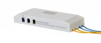
Motion sensor device
The design of the sensor contains two parts - a fixed one, which is attached to the surface, and a movable one. The moving part has two degrees of freedom and can rotate 30-400 in horizontal and vertical planes.
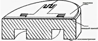
When disassembled, the LX-02 motion sensor looks like this:
View of boards from the parts side
View from the back side (from the soldering side):
View of the motion sensor boards from the solder side
The device uses the following main parts:
- The chip is LM324, these are four operational amplifiers in one package. The datasheet can be downloaded here: • LM324,224,2902 Operational Amplifiers.pdf / , pdf, 134.11 kB, downloaded: 3855 times./
- motion sensor – PIR D203S or 1VY7015
- transistor type S9013 - bipolar medium power. The datasheet can be downloaded here: • S9013 / , pdf, 62.29 kB, downloaded: 2024 times./
- relay SHD-24VDC-FA.
On the side of the microcircuit key there is a light control, next to it there is an on-time control.
Do it yourself
Today, a lot of ready-made PIR blocks of industrial production are offered. But why not try to assemble it yourself? You can make a capable module for turning on the light yourself, the main thing is to have basic skills in reading electrical circuits and soldering. Although the diagrams usually used by craftsmen do not require the presence of a large number of expensive parts, a lot of time will have to be spent on assembly.
Sensor assembly
Ithaca, for the above circuit you will need: B1 - the PIR sensor itself, VT 1 - field-effect transistor, VD 1 - photodiode, VD 2, VD 3 - diodes, VD 4, VD 6 - diode bridges, VD 5 - zener diode, T 1 – transformer, DA1 – parallel stabilizer timer, DA2 – analog timer, DA3 – linear regulator, VU1 – optocoupler, FU1 – fuse, R1 – R11 – resistors, C1 – C4 – capacitors, HL1 – LED.
The end result should look like this. The device turns out to be quite compact - 15.0 × 6.0 × 9.0 cm. If configured, it can detect the movements of warm-blooded objects at a distance of 1-12 meters from the sensor. And it consumes an insignificant 5 watts.
Final result
Both incandescent and energy-saving lamps can be connected to such a system. However, the maximum power load threshold of 1000 W should not be exceeded. Fortunately, it is not at all necessary to pore over the boards, because buying such modules is not a problem. On product websites (manufactured in China) you will find a lot of offers of ready-made PIR circuits starting from 70 rubles. They can be connected directly to your existing lighting system.
Motion sensor circuits
The sensor circuit looks something like this.
Diagram of motion sensor LX-02 and analogues
Here is another similar scheme, but simpler. This is a security sensor circuit. I express my gratitude to the source – www.guarda.ru.
Motion Sensor. Scheme 2
In different sensor models, the circuit may vary slightly, but the operating principle is the same. Briefly it can be described as follows.
The signal from the pyro sensor (most often used is 1vy7015) goes to the amplifier, then the comparator operates, from the output of which the signal goes through the transistor to the relay coil. The relay turns the load on and off with its contacts.
The 4 microcircuits shown in the diagram should not be misleading - in fact, this is one microcircuit, in the case of which there are 4 operational amplifiers with a common power supply.
The third diagram is given at the end of the article.
Motion sensor for turning on the light with your own hands: 3 elements
It’s easier to make a homemade DD with an infrared or ultrasonic sensor. Such a device consists of a transmitter, receiver and power supply. The power supply can be any 12 V. The transmitter is assembled using an NE 555 microcircuit, and the transmitting element is an LD 274 diode with a viewing angle of 10°.
The BPW40 phototransistor acts as the sensitive element of the receiver and controls the entire BS-115C relay. When installing, you need to take into account that the viewing angle of the phototransistor is 20°. With this assembly, the distance between the transmitter and receiver will be 5 meters.
Connecting a motion sensor
Connecting a motion sensor requires a little more skill than connecting a regular switch. By mixing up the sensor leads, you can burn both the sensor itself and the electrical wiring. Especially if it is not properly protected.
I had this happen when the instructions indicated certain wire colors, but in reality they were different.
The motion sensor and light sensor (photo relay, or twilight relay) are connected in exactly the same way, so in the diagram below the source of influence is indicated by light.
Pins for connecting motion sensor and light sensor
Motion and light sensor connection diagram.
As you can see, this connection diagram is no different from the diagram for turning on a light bulb through a regular switch. The only difference is that the neutral wire is also involved in the connection, and that the switch is acted upon by a human hand, and the sensor is acted upon by movement or light.
How to connect a motion sensor is also shown in the diagram in the instructions (below).
The diagram also shows the colors of the wires. Also, terminal designations are usually stamped on the housing near each terminal.
Color of leads for connecting LX sensor:
- brown (black) – phase input (to turn on the lighting and power the internal circuit)
- blue (green, blue) – zero for powering the electronic circuit of the sensor, not used for powering lighting.
- red – phase output (load connection)
The load (light bulb) is connected to zero and the output.
It is worth noting that such color marking is not mandatory for the manufacturer. Even from the same manufacturer, the same terminals may have different wire colors. Therefore, you need to refer to the instructions, and if in doubt, disassemble the sensor and look at the connection of the wires on the board.
How to connect a DD via a switch: 3 types of devices
Variety 1 - regular switch
Installation begins with connecting the cable to the sensor. There are two types of cable entry into the detector: from the back or from the side. The rear connection is most often used for hidden wiring, and the side connection is used for external laying of the power cable.
At the next stage, we connect the cable conductors to the terminals of the device. Then we attach the device directly to the ceiling or wall. The connection to the switch occurs through the phase to the wire located between the light bulb and the DD.
You can also use an existing switch. In this case, we replace the existing single switch with a double one, in which the free contact will supply power to the sensor. If there is a double switch in use, then it needs to be changed to a triple one.
It is also important to know 3 installation recommendations
- Manufacturers do not recommend connecting DDs to energy-saving lamps due to the fact that their service life is significantly reduced;
- Trees and shrubs should not be in the field of view of a device installed outdoors; they can emit heat, which negatively affects the operation of the equipment;
- You need to direct the beam of action in the direction where there is a need to turn on the lighting when a moving object is detected.
Variety 2 - DD with smooth switching on and off of lighting
The infrared detector independently controls the level of illumination, but special equipment is required for smooth switching on and off. The microcontroller, having received a signal from the sensor, is able to slowly increase the brightness of the lamp, and when the signal disappears, gradually reduce the brightness to zero. The smoothness is adjustable within wide limits, and the process lasts several minutes.
Type 3 - automatic light switch with DD
Such equipment is capable of turning on and off lighting fixtures without pressing. The device reacts to the movement of objects and independently controls manipulations. The device is capable of monitoring an area at a distance of up to 8 meters.
Instructions for the motion sensor
Since this article discusses the LX-02 (SEN15) model, instructions for this sensor are given below.
Instructions for motion sensor LX-02
That's basically all I wanted to tell you about the device and circuit of the motion sensor .
By the way, I have several more articles regarding this topic:
- Description, application and parameters
- Installation of street sensors over large areas
- Various advanced switching schemes
- LED lamp
The topic of sensor repair is covered in the article Do-it-yourself motion sensor repair. Step by step guide. A motion sensor circuit based on a specialized LP8072C microcircuit is also shown and discussed there.
Complex application
The best method of increasing the sensitivity of thermal motion detectors is to use them in combination with similar ones, but operating on different physical principles:
- Trapping optical waves (change in lighting).
- Sound - while moving, all objects produce air vibrations audible to the ear.
- Echolocating is when equipment creates a directed wave pulse (invisible to human eyes) and receives the signal reflected from objects to sensors. Based on its change, a conclusion is drawn about the movements of something in the controlled field.
Each of the detectors listed has pros and cons depending on their detection methods. But, working together, they create for the overall system an almost complete range of feelings for determining movements in the sensory field. Roughly speaking, they can see, hear and sense human movements.
Another sensor circuit
Reader Alexander from Korolev in December 2014 sent another motion sensor circuit, which he copied from the board with his own hands. Photo is also attached.
Motion sensor circuit 3
And here are oscillograms explaining the operation of the circuit:
Oscillogram 1 of the sensor circuit operation
Oscillogram 2 of motion sensor operation
Motion sensor board. Board model – 94vo-d
Alexander, thank you! Good luck in job!
IR transmitter code
We will use timers to generate bursts of pulses with signal output to a specific pin. Thus, the MK kernel only initializes these timers, and then can do some other work.
The choice of pin must be justified. It is necessary to select a pin to which any channel (except the fourth) of any General-purpose timer can be connected. In our case, pin PB6 is selected, the first TIM4 channel is connected to it. The receiver will be connected to pin PB7, the second channel is TIM4.
We will use two timers: TIM4 will generate a square wave with a frequency of 56 kHz, TIM2 will control the TIM4 timer, i.e. create packs from meander. TIM2 will operate in Master mode, TIM4 – Slave. Why TIM2 timer? It was selected based on the datasheet table of connections of timers to each other.
Let's start writing the Tim_Init_Transmitter() function for initializing timers. The code is written for an empty project. First, we declare a function, initialize it in the body of main, and after main we write the function itself.
#include "main.h" void Timer_Init_Transmitter(void); int main(void) { RCC->ICSCR |= RCC_ICSCR_MSIRANGE_6; // MSI 4.194 MHz enable Timer_Init_Transmitter(); while(1) { } } void Timer_Init_Transmitter(void) { }
RCC->ICSCR |= RCCICSCRMSIRANGE_6 - this line simply sets the frequency of the MK to 4.194 MHz. You can have any other frequency.
Setting up a pin. We turn on clocking, turn on the alternative function, select a higher pin speed (this is not necessary), select which alternative function we want to connect to the pin. Everything is described in detail under the spoilers.
More information about enabling clocking
In the datasheet we find the RCC_AHBENR register. You need to enter “1” in the GPIOBEN field.
To do this, select the line RCC_AHBENR_GPIOBEN in the CMSIS library, which sets this bit to one.
And change the AHBENR register as follows:
RCC->AHBENR |= RCC_AHBENR_GPIOBEN; //GPIO port B clock enable
Learn more about enabling an alternative function
In the datasheet we find the GPIOx_MODER register. You need to enter “10” in the MODER6 field (for pin PB6).
To do this, select the line GPIO_MODER_MODER6_1 in the CMSIS library, which sets the second bit to one.
In what follows, all such notations will be taken similarly.
And change the MODER register as follows:
GPIOB->MODER |= GPIO_MODER_MODER6_1; //Alternative function mode enable
Enabling high speed for a pin is done in the same way as enabling an alternative function.
Learn more about choosing an alternative function
The designation of alternative functions is presented in the picture below.
We need an alternative function for TIM4 - this is AF2.
It is worth noting that there are two registers for selecting alternative functions: the lower GPIOx_AFRL for pins with numbers from 0 to 7 and the upper GPIOx_AFRH for pins with numbers from 8 to 15. However, the CMSIS library defines a double register AFR[2], writing in brackets “0”, we select lower case; by writing “1”, we select upper case.
In the datasheet we find the GPIOx_AFRL register.
We need to write “0010” in the AFRL6 field, for this we need a number in hexadecimal form 0x2000000, “2” is the seventh from the right for pin PB6, because the first six digits are for pins with numbers from 0 to 5.
And change the AFRL register as follows:
GPIOB->AFR[0] |= 0x2000000; //Pin PB6 TIM4 alternative function AF2 enable
We received the following code to configure the pin inside our function:
void Timer_Init_Transmitter (void) { //Settings for GPIO PB6 RCC->AHBENR |= RCC_AHBENR_GPIOBEN; //GPIO port B clock enable GPIOB->MODER |= GPIO_MODER_MODER6_1; //Alternative function mode enable GPIOB->OSPEEDR |= GPIO_OSPEEDER_OSPEEDR6_1; //High speed GPIOB->AFR[0] |= 0x2000000; //Pin PB6 TIM4 alternative function AF2 enable }
Now let's move on to setting up TIM4.
We need to select the PSC prescaler (frequency divider), calculate the values for the CCR1 (pulse width) and ARR (pulse period) registers, select the operating mode of the PWM timer, select the input control signal from the TIM2 timer, select the mode for the Slave and apply the timer output signal to pin PB6.
Enabling clocking is similar to enabling GPIO clocking.
Read more about choosing a PSC prescaler and calculating CCR1 and ARR
Let us choose the value of the input frequency preselector equal to 0, in this case the clock frequency of the timer will be equal to the frequency of the microcontroller.
And change the PSC register as follows:
TIM4->PSC = 0; //Prescaler value
Let's move on to calculating ARR.
To calculate ARR, we need to divide the clock frequency of the 4.194 MHz timer (you have your own) by 56 kHz. We get 74.89, round to the nearest whole number. I rounded to 75. And enter into the ARR register:
TIM4->ARR = 75 //Auto-reload value
All that remains is to calculate CCR1.
Since we have a simple square wave, then in the CCR1 register in PWM mode we need to specify half of the ARR value:
TIM4->CCR1 = 37; //Capture/Compare 1 value
More information about choosing the operating mode of the PWM timer
Since we have the first channel, we use the CCMR1 register. We are interested in the OC1M field in this register. PWM mode allows you to adjust the pulse duration at a fixed period.
Let's select PMW mode 1 by entering two ones in the second and third bits, i.e. "110":
TIM4->CCMR1 |= TIM_CCMR1_OC1M_1 | TIM_CCMR1_OC1M_2; //Output compare PMW mode 1
More details about setting the output signal to pin PB6
In the CCER register, in the CC1E field, you need to enter “1”, turning on the output signal to the pin.
Enter the following line:
TIM4->CCER |= TIM_CCER_CC1E; //OC3 signal is output on the corresponding pin
Read more about choosing a control signal and Slave mode
To control TIM4 timer TIM2, you need to select the input signal ITR1. To do this, enter “001” in the TS field of the TIMx_SMCR register. We will also select the mode for Slave by entering “101” in the SMS field. In this mode, as long as the input signal ITR1 is high, TIM4 will work and output a square wave to the pin; as soon as ITR1 becomes low, TIM4 turns off.
To do this, enter:
TIM4->SMCR |= TIM_SMCR_TS_0; //choosing ITR1
TIM4->SMCR |= TIM_SMCR_SMS_0 | TIM_SMCR_SMS_2; //Gated Mode
Let's add to the existing code, and we get:
void Timer_Init_Transmitter (void) { //Settings for GPIO PB6 RCC->AHBENR |= RCC_AHBENR_GPIOBEN; //GPIO port B clock enable GPIOB->MODER |= GPIO_MODER_MODER6_1; //Alternative function mode enable GPIOB->OSPEEDR |= GPIO_OSPEEDER_OSPEEDR6_1; //High speed GPIOB->AFR[0] |= 0x2000000; //Pin PB6 TIM4 alternative function AF2 enable //Settings for TIM4 — Slave RCC->APB1ENR |= RCC_APB1ENR_TIM4EN; //TIM4 clock enable TIM4->PSC = 0; //Prescaler value TIM4->ARR = 75; //Auto-reload value TIM4->CCR1 = 37; //Capture/Compare 1 value TIM4->CCMR1 |= TIM_CCMR1_OC1M_1 | TIM_CCMR1_OC1M_2; //Output compare PMW mode 1 enable TIM4->CCER |= TIM_CCER_CC1E; //OC3 signal is output on the corresponding output pin TIM4->SMCR |= TIM_SMCR_TS_0; //choosing ITR1 TIM4->SMCR |= TIM_SMCR_SMS_0 | TIM_SMCR_SMS_2; //Gated Mode TIM4->CR1 |= TIM_CR1_CEN; //TIM4 enable }
TIM4 can be turned on, or not, since the control signal from TIM2 will still turn it on.
Now let's move on to setting up TIM2.
It is necessary to clock the timer, calculate PSC, CCR1 and ARR, select the operating mode of the PWM timer, select which signal will be the output (input control for TIM4) and turn on the timer.
Enabling clocking is the same as for the TIM4 timer.
RCC->APB1ENR |= RCC_APB1ENR_TIM2EN; //TIM2 clock enable
More details about calculating PSC, CCR1 and ARR for TIM2
Since, according to the datasheet, at least 10 pulses should be used per diode in a pack (in fact, less is possible, but the quality of work may not be very good), we will choose to clock the TIM2 timer ten times less than TIM4.
As we can see in the formula for calculating the clock frequency of the timer, the denominator already contains “+1”, i.e. we need to write “9” to the PSC register to get a frequency 10 times lower than the MK frequency.
TIM2->PSC = 9; //Prescaler value
Now let's calculate the value for CCR1: we will send 10 pulses, therefore, we need to take the ARR value for TIM4 (the period of one pulse is 75) and multiply by 10, i.e. we get 750, however, we have a prescaler that divides the frequency by 10, i.e. we need to divide 750 by 10, in the end we get 75 again (as in TIM4, but with a different prescaler). Let's write this value to the CCR1 register of the TIM2 timer.
TIM2->CCR1 = 75; //Capture/Compare 1 value
Let's move on to calculating ARR: everything is simple here, let's say we want to “shoot” bursts with a duty cycle of 11.2, while the period of emission of bursts will be about 2 ms (based on the calculation that 1 ms is 4194000/1000 = 4194 ticks, and multiply by 2, we get rounded up 8400, and with a prescaler of 10, we get 840 ticks), multiply the duration of a burst of 75 by 11.2 and get 840, as you can see, the values are the same. Let's write this to the ARR register.
TIM2->ARR = 840; //Auto-reload value
According to the datasheet, the duty cycle should be at least 2, but with such values the stability of operation will be worse, and such data transmission is only suitable for short bursts. For long parcels and large bursts, the duty cycle should be greater than 4.
The operating mode of the TIM2 timer is exactly the same as that of TIM4 - PWM.
TIM2->CCMR1 |= TIM_CCMR1_OC1M_1 | TIM_CCMR1_OC1M_2; //Output compare PMW mode 1 enable
More details about selecting the TIM2 output signal (controlling for TIM4)
Let's find the TIMx_CR2 register.
We need to send a signal from the first channel (we use CCR1) to the output from the TIM2 timer. This signal is OC1REF. Below in the picture you can find the combination of bits for this signal - “100”.
In the MMS field, you must enter “1” in the third bit.
TIM2->CR2 |= TIM_CR2_MMS_2; //OC1REF signal is used as trigger output (TRGO)
Now all that remains is to enable TIM2 by writing the following line:
TIM2->CR1 |= TIM_CR1_CEN; //TIM2 enable
In this case, when the MK is turned on, the diode will begin to emit. If you want to turn on the diode at a certain time, then in our function you need to remove two lines with the inclusion of timers, and simply turn on TIM2 at the right moment.
Add these lines to the previous ones and get:
void Timer_Init_Transmitter (void) { //Settings for GPIO PB6 RCC->AHBENR |= RCC_AHBENR_GPIOBEN; //GPIO port B clock enable GPIOB->MODER |= GPIO_MODER_MODER6_1; //Alternative function mode enable GPIOB->OSPEEDR |= GPIO_OSPEEDER_OSPEEDR6_1; //High speed GPIOB->AFR[0] |= 0x2000000; //Pin PB6 TIM4 alternative function AF2 enable //Settings for TIM4 — Slave RCC->APB1ENR |= RCC_APB1ENR_TIM4EN; //TIM4 clock enable TIM4->PSC = 0; //Prescaler value TIM4->ARR = 75; //Auto-reload value TIM4->CCR1 = 37; //Capture/Compare 1 value TIM4->CCMR1 |= TIM_CCMR1_OC1M_1 | TIM_CCMR1_OC1M_2; //Output compare PMW mode 1 enable TIM4->CCER |= TIM_CCER_CC1E; //OC3 signal is output on the corresponding output pin TIM4->SMCR &= ~TIM_SMCR_TS; //clear bits TIM4->SMCR |= TIM_SMCR_TS_0; //choosing ITR1 TIM4->SMCR &= ~TIM_SMCR_SMS; //clear bits TIM4->SMCR |= TIM_SMCR_SMS_0 | TIM_SMCR_SMS_2; //Gated Mode TIM4->CR1 |= TIM_CR1_CEN; //TIM4 enable //Settings for TIM2 - Master RCC->APB1ENR |= RCC_APB1ENR_TIM2EN; //TIM2 clock enable TIM2->PSC = 9; //Prescaler value TIM2->ARR = 840; //Auto-reload value TIM2->CCR1 = 75; //Capture/Compare 1 value TIM2->CCMR1 |= TIM_CCMR1_OC1M_1 | TIM_CCMR1_OC1M_2; //Output compare PMW mode 1 enable TIM2->CR2 |= TIM_CR2_MMS_2; //OC1REF signal is used as trigger output (TRGO) TIM2->CR1 |= TIM_CR1_CEN; //TIM2 enable }
Now our IR diode will emit packs of 10 pulses, with a frequency of 56 kHz, with a duty cycle of 11.2, i.e. with a burst repetition period of 2 ms. Note that the moment of intersection of any object within the period of the packs is not determined, i.e. we can judge the intersection of the IR beam only by the absence of the next burst. Thus, the error in measuring the moment of beam intersection is 2 ms.
Appearance of the motion sensor
A couple more photos of what the motion sensor board might look like when disassembled.
Motion sensor board. Solder side
Motion sensor board. View from the parts
If anything is not clear or you have something to add, ask and write in the comments. If you are interested in what I will publish next on my blog SamElectric.ru, subscribe to receive new articles.
How to avoid 3 installation mistakes
- Installation location. The device must be installed in the location that is most suitable according to the technical conditions. There are cases when a ceiling detector is mounted on a wall, which leads to incorrect operation.
- Installation of lens masks. These curtains are included in the DD kit and are intended to adjust the coverage area. If they are not removed after adjustment, the device will not detect movement.
- Incorrect switch position. If you install a switch before the sensor, the power will turn off and the operation of the device will become impossible.
Additionally
If you want the diode on the receiver to light up when an IR signal is received, and not light up when there is no signal at the receiver input, then you need to slightly change the code for the receiver.
You need to add a global variable, for example, by writing the following line between “includes” and main:
int StatusDiode = 0; // 0 — diode is off, 1 — diode is on
This variable is needed to remember the status of the LED: off or on.
Next, in the timer initialization function, you need to change the line from allowing overflow interruption to enabling trigger interruption, with the following line:
TIM4->DIER |= TIM_DIER_TIE; //Trigger interrupt enable
And the last thing: let's change the interrupt handler.
Accordingly, if the diode was turned off and our trigger interrupt was triggered, then we remove the corresponding flag, turn on the diode, turn off trigger interrupt enable, enable overflow interrupt enable, reset the counter (you don’t have to do this step) and change the status of the diode.
If the diode was turned on, we do the opposite: remove the corresponding flag, turn off the diode, turn off the overflow interrupt enable, enable the trigger interrupt enable and change the status of the diode.
It is worth remembering that the counter does not stop unless the timer is turned off, however, when interrupted by an overflow, it is rebooted (the CNT register is updated), and when interrupted by a trigger, the update does not occur, so we reset it.
We get the following interrupt handler:
void TIM4_IRQHandler(void) { if (StatusDiode == 0) { TIM4->SR &= ~TIM_SR_TIF; GPIOB->ODR |= GPIO_ODR_ODR_15; // Led red on TIM4->DIER &= ~TIM_DIER_TIE; // Trigger interrupt disable TIM4->DIER |= TIM_DIER_CC2IE; // Capture/Compare 2 interrupt enable TIM4->CNT = 0; StatusDiode = 1; } else { TIM4->SR &= ~TIM_SR_CC2IF; GPIOB->ODR &= ~GPIO_ODR_ODR_15; // Led red off TIM4->DIER &= ~TIM_DIER_CC2IE; // Capture/Compare 2 interrupt disable TIM4->DIER |= TIM_DIER_TIE; // Trigger interrupt enable StatusDiode = 0; } } Complete code for the IR signal receiver
#include “main.h” void Timer_Init_Receiver(void); int main(void) { RCC->ICSCR |= RCC_ICSCR_MSIRANGE_6; // MSI 4.194 MHz enable GPIOB->MODER |= GPIO_MODER_MODER15_0; // PB15 output mode Timer_Init_Receiver(); while(1) { } } void Timer_Init_Receiver(void) { //Settings for GPIO PB7 RCC->AHBENR |= RCC_AHBENR_GPIOBEN; // GPIO port B clock enable GPIOB->MODER |= GPIO_MODER_MODER7_1; // Alternative function mode enable GPIOB->OSPEEDR |= GPIO_OSPEEDER_OSPEEDR7_1; // High speed GPIOB->PUPDR |= GPIO_PUPDR_PUPDR7_0; // pull-up PB7 GPIOB->AFR[0] |= 0x20000000; // Pin PB7 TIM4 alternative function AF2 enable //Settings for TIM4 RCC->APB1ENR |= RCC_APB1ENR_TIM4EN; // TIM4 clock enable TIM4->PSC = 9; // Prescaler value TIM4->ARR = 4200; // Auto-reload value TIM4->CCR2 = 4200; // Capture/Compare 2 value TIM4->CCMR1 &= ~TIM_CCMR1_OC2M; // Frozen mode enable TIM4->CCMR1 &= ~TIM_CCMR1_CC2S; // Output mode TIM4->CCER &= ~TIM_CCER_CC2NP; // This bit is used in conjunction with CC2P. TIM4->CCER |= TIM_CCER_CC2P; // Inverted/falling edge TIM4->SMCR |= TIM_SMCR_TS_1 | TIM_SMCR_TS_2; // Choosing TI2FP2 TIM4->SMCR |= TIM_SMCR_SMS_2; // Reset mode TIM4->DIER |= TIM_DIER_TIE; // Trigger interrupt enable TIM4->CR1 |= TIM_CR1_CEN; // TIM4 enable NVIC_EnableIRQ(TIM4_IRQn); // TIM4 global Interrupt enable } void TIM4_IRQHandler(void) { if (StatusDiode == 0) { TIM4->SR &= ~TIM_SR_TIF; GPIOB->ODR |= GPIO_ODR_ODR_15; // Led red on TIM4->DIER &= ~TIM_DIER_TIE; // Trigger interrupt disable TIM4->DIER |= TIM_DIER_CC2IE; // Capture/Compare 2 interrupt enable TIM4->CNT = 0; StatusDiode = 1; } else { TIM4->SR &= ~TIM_SR_CC2IF; GPIOB->ODR &= ~GPIO_ODR_ODR_15; // Led red off TIM4->DIER &= ~TIM_DIER_CC2IE; // Capture/Compare 2 interrupt disable TIM4->DIER |= TIM_DIER_TIE; // Trigger interrupt enable StatusDiode = 0; } }
Full code
IR signal transmitter code
void Timer_Init_Transmitter(void); int main(void) { RCC->ICSCR |= RCC_ICSCR_MSIRANGE_6; // MSI 4.194 MHz enable Timer_Init_Transmitter(); while(1) { } } void Timer_Init_Transmitter(void) { //Settings for GPIO PB6 RCC->AHBENR |= RCC_AHBENR_GPIOBEN; //GPIO port B clock enable GPIOB->MODER |= GPIO_MODER_MODER6_1; //Alternative function mode enable GPIOB->OSPEEDR |= GPIO_OSPEEDER_OSPEEDR6_1; //High speed GPIOB->AFR[0] |= 0x2000000; //Pin PB6 TIM4 alternative function AF2 enable //Settings for TIM4 — Slave RCC->APB1ENR |= RCC_APB1ENR_TIM4EN; //TIM4 clock enable TIM4->PSC = 0; //Prescaler value TIM4->ARR = 75; //Auto-reload value TIM4->CCR1 = 37; //Capture/Compare 1 value TIM4->CCMR1 |= TIM_CCMR1_OC1M_1 | TIM_CCMR1_OC1M_2; //Output compare PMW mode 1 enable TIM4->CCER |= TIM_CCER_CC1E; //OC3 signal is output on the corresponding output pin TIM4->SMCR &= ~TIM_SMCR_TS; //clear bits TIM4->SMCR |= TIM_SMCR_TS_0; //choosing ITR1 TIM4->SMCR &= ~TIM_SMCR_SMS; //clear bits TIM4->SMCR |= TIM_SMCR_SMS_0 | TIM_SMCR_SMS_2; //Gated Mode TIM4->CR1 |= TIM_CR1_CEN; //TIM4 enable //Settings for TIM2 - Master RCC->APB1ENR |= RCC_APB1ENR_TIM2EN; //TIM2 clock enable TIM2->PSC = 9; //Prescaler value TIM2->ARR = 840; //Auto-reload value TIM2->CCR1 = 75; //Capture/Compare 1 value TIM2->CCMR1 |= TIM_CCMR1_OC1M_1 | TIM_CCMR1_OC1M_2; //Output compare PMW mode 1 enable TIM2->CR2 |= TIM_CR2_MMS_2; //OC1REF signal is used as trigger output (TRGO) TIM2->CR1 |= TIM_CR1_CEN; //TIM2 enable }
IR receiver code
#include “main.h” void Timer_Init_Receiver(void); int main(void) { RCC->ICSCR |= RCC_ICSCR_MSIRANGE_6; // MSI 4.194 MHz enable GPIOB->MODER |= GPIO_MODER_MODER15_0; // PB15 output mode Timer_Init_Receiver(); while(1) { } } void Timer_Init_Receiver(void) { //Settings for GPIO PB7 RCC->AHBENR |= RCC_AHBENR_GPIOBEN; // GPIO port B clock enable GPIOB->MODER |= GPIO_MODER_MODER7_1; // Alternative function mode enable GPIOB->OSPEEDR |= GPIO_OSPEEDER_OSPEEDR7_1; // High speed GPIOB->PUPDR |= GPIO_PUPDR_PUPDR7_0; // pull-up PB7 GPIOB->AFR[0] |= 0x20000000; // Pin PB7 TIM4 alternative function AF2 enable //Settings for TIM4 RCC->APB1ENR |= RCC_APB1ENR_TIM4EN; // TIM4 clock enable TIM4->PSC = 9; // Prescaler value TIM4->ARR = 4200; // Auto-reload value TIM4->CCR2 = 4200; // Capture/Compare 2 value TIM4->CCMR1 &= ~TIM_CCMR1_OC2M; // Frozen mode enable TIM4->CCMR1 &= ~TIM_CCMR1_CC2S; // Output mode TIM4->CCER &= ~TIM_CCER_CC2NP; // This bit is used in conjunction with CC2P. TIM4->CCER |= TIM_CCER_CC2P; // Inverted/falling edge TIM4->SMCR |= TIM_SMCR_TS_1 | TIM_SMCR_TS_2; // Choosing TI2FP2 TIM4->SMCR |= TIM_SMCR_SMS_2; // Reset mode TIM4->DIER |= TIM_DIER_CC2IE; // Capture/Compare 2 interrupt enable TIM4->CR1 |= TIM_CR1_CEN; // TIM4 enable NVIC_EnableIRQ(TIM4_IRQn); // TIM4 global Interrupt enable } void TIM4_IRQHandler(void) { TIM4->SR &= ~TIM_SR_CC2IF; GPIOB->ODR |= GPIO_ODR_ODR_15; // Led red on }