Every day people are faced with the use of electronic devices. Modern life is impossible without them. After all, we are talking about TV, radio, computer, telephone, multicooker and so on. Previously, just a few years ago, no one thought about what signal was used in each working device. Now the words “analog”, “digital”, “discrete” have been around for a long time. Some types of signals listed are of high quality and reliable.
Digital transmission came into use much later than analogue. This is due to the fact that such a signal is much easier to maintain, and the technology at that time was not so improved.
Every person encounters the concept of “discreteness” all the time. If you translate this word from Latin, it will mean “discontinuity.” Delving far into science, we can say that a discrete signal is a method of transmitting information, which implies a change in time of the carrier medium. The latter takes any value from all possible. Now discreteness is fading into the background, after the decision was made to produce systems on a chip. They are holistic, and all components closely interact with each other. In discreteness, everything is exactly the opposite - each detail is completed and connected to others through special communication lines.
Signal
A signal is a special code that is transmitted into space by one or more systems. This formulation is general.
In the field of information and communications, a signal is a special data carrier that is used to transmit messages. It can be created, but not accepted; the latter condition is not necessary. If the signal is a message, then “catching” it is considered necessary.
The described data transmission code is specified by a mathematical function. It characterizes all possible changes in parameters. In radio engineering theory, this model is considered basic. In it, noise was called an analogue of the signal. It represents a function of time that freely interacts with the transmitted code and distorts it.
The article describes the types of signals: discrete, analog and digital. The basic theory on the topic described is also briefly given.
Creation and formatting
Many types of information signals that we will talk about in the article need to be created and then formatted. To do this, you must have a digital-to-analog converter, as well as an analog-to-digital converter. As a rule, they are both used in the same situation: only in the case of using a technique such as DSP.
In other cases, only the first device will do. In order to create physical analog codes and then reformat them into digital methods, it is necessary to use special devices. This will prevent damage to information as much as possible.
Types of signals
There are several types of classification of available signals. Let's look at what types there are.
- Based on the physical medium of the data carrier, they are divided into electrical, optical, acoustic and electromagnetic signals. There are several other species, but they are little known.
- According to the method of setting, signals are divided into regular and irregular. The first are deterministic methods of data transmission, which are specified by an analytical function. Random ones are formulated using the theory of probability, and they also take on any values at different periods of time.
- Depending on the functions that describe all signal parameters, data transmission methods can be analog, discrete, digital (a method that is quantized in level). They are used to power many electrical appliances.
Now the reader knows all types of signal transmission. It won’t be difficult for anyone to understand them; the main thing is to think a little and remember the school physics course.
Basic audio file formats
In fact, there are a lot of formats with which you can read audio files. But there are those that have received universal recognition. All of them are divided into three groups:
- uncompressed audio formats;
- with lossless compression;
- with lossy compression.
Let's look at the main audio file formats:
- WAV is the first audio format that could be processed by computer programs at a high professional level. Disadvantage: recording takes up too much space.
- CDs - The .cda extension cannot be edited, but it can be reformatted and saved with any audio processing program.
- MP3 codec is a universal format that compresses audio files as much as possible.
- AIFF files - the format supports monophonic and stereophonic data of 8 and 16 bits in size, was originally developed for the Macintosh, but after additional development it can be used on other OS platforms.
- OGG is a popular format, but it has disadvantages such as the use of its own codecs and decoders and overloading the computer's system resources.
- AMR is a low-quality audio format.
- The MIDI format allows you to edit a recording by pressing keys, changing tempo, key, pitch, and adding effects.
- FLAC is a format that reproduces audio in high quality.
Why is the signal processed?
The signal is processed in order to transmit and receive information that is encrypted in it. Once it is extracted, it can be used in a variety of ways. In some situations it will be reformatted.
There is another reason for processing all the signals. It consists of a slight compression of frequencies (so as not to damage the information). After this, it is formatted and transmitted at slow speeds.
Analog and digital signals use special techniques. In particular, filtering, convolution, correlation. They are necessary to restore the signal if it is damaged or has noise.
Where to apply?
In what cases should analogue video surveillance be used, and in which digital? Analog video cameras:
- In case of a very limited budget. It is usually better to install more cheaper cameras.
- In case of poor Internet quality. Analogue cameras impose fewer requirements on the data transmission channel, so they are more suitable for remote access at sites where the Internet is weak: dachas, country houses, objects remote from city infrastructure.
- In case of system expansion. Existing analog cameras can usually be expanded only with analog cameras. We change the recorder, connect old analog cameras, and expand the system with additional analog cameras.
- In case of a large distance between the cameras and the recorder. Perimeter security, large-area objects.
- In case of a small number of cameras. As a rule, analog video surveillance systems include no more than 16 cameras.
Digital cameras:
- When high signal quality is required. Parking lots, shopping centers, ticket offices, entrance areas, gates, etc. When maximum signal quality is required.
- When there is a ready-made data network. A regular computer network can be used to transmit data from analog cameras. In this way, the budget for pulling cables can be significantly saved.
- When video analytics is required. People counting, number plate recognition, shelf occupancy detection, etc.
- When it is known in advance that the system will expand. A system built on digital cameras is easier to expand.
- In cases where it is necessary to install a large number of video cameras. As a rule, in this case the number of cameras is in the tens or even hundreds.
Dynamic range
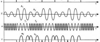
The signal range is calculated by the difference between the higher and lower volume levels, which are expressed in decibels. It completely depends on the work and the characteristics of the performance. We are talking about both musical tracks and ordinary dialogues between people. If we take, for example, an announcer who reads the news, then his dynamic range fluctuates around 25-30 dB. And while reading any work, it can rise to 50 dB.
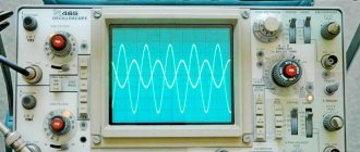
Analog signal
An analog signal is a time-continuous method of data transmission. Its disadvantage is the presence of noise, which sometimes leads to a complete loss of information. Very often situations arise that it is impossible to determine where the important data is in the code and where there are ordinary distortions.
It is because of this that digital signal processing has gained great popularity and is gradually replacing analog.
History of the term
The appearance of the term denoting this method of data transmission is closely related to such areas as computer technology, telephony and the recording industry, and electrical measurements.
Computer Engineering
In the 40s, the first computing systems were created to collect and process digital information. In the early 80s, with the advent of new computer models based on Intel processors, the capabilities of computing technology expanded. It was during this period that this term appeared.
Sound recording and telephony
The concept of a continuous method of data transmission is initially associated with telephony. Continuous vibrations are sent to the device's speaker, become an electrical analogue, and are then converted into a signal similar to a voice.
Electrical measurements
A continuous stream is reproduced by the receiving device in proportion to electrical parameters such as voltage and current. It is with the beginning of the measurement of the above electrical quantities that the appearance of this term is associated.
Digital signal
A digital signal is a special data stream; it is described by discrete functions. Its amplitude can take on a certain value from those already specified. If an analog signal is capable of arriving with a huge amount of noise, then a digital signal filters out most of the received noise.
In addition, this type of data transmission transfers information without unnecessary semantic load. Several codes can be sent at once through one physical channel.
There are no types of digital signal, since it stands out as a separate and independent method of data transmission. It represents a binary stream. Nowadays, this signal is considered the most popular. This is due to ease of use.
How DACs build a wave
A DAC is a digital-to-analog converter, an element that converts digital sound into analog. We will look superficially at the basic principles. If the comments indicate an interest in considering a number of points in more detail, a separate material will be released.
Multibit DACs
Very often, a wave is represented as steps, which is due to the architecture of the first generation of multi-bit R-2R DACs, which operate similarly to a relay switch.
Their improved control structures could not be well represented by flowcharts. Thus, pseudocode was developed. Instead of spending a lot of time on the mechanics of the flowchart, spend time making the pseudocode more precise. The modern complexity of firmware is a good match for presenting pseudocode. Learning and using pseudocode is a great way to understand some of the firmware. Once you learn to write, it is much easier and faster than drawing a flowchart. Pseudocode is easy to write for those familiar with the basics of modern programming languages.
The DAC input receives the value of the next vertical coordinate and at each clock cycle it switches the current (voltage) level to the appropriate level until the next change.
Although it is believed that the human ear can hear no higher than 20 kHz, and according to Nyquist theory it is possible to restore the signal up to 22 kHz, the question remains about the quality of this signal after restoration. In the high-frequency region, the resulting “stepped” waveform is usually far from the original one. The easiest way out of the situation is to increase the sampling frequency when recording, but this leads to a significant and undesirable increase in file size.
Test and measurement
This is a very important part of firmware design.
Learning this will help you understand the firmware culture. The flowchart fragment shown took half an hour to complete, but the flowchart only contains about nine lines of pseudocode. Analog signals are easily accessible for testing and debugging. In firmware, everything is hidden in the processor, thus running "inside the box". The built-in emulator is the most commonly used tool for software debugging. You can test and modify registers and memory, step through a program, set breakpoints to stop the program when it executes certain instructions, and so on. However, the emulator is of little use for debugging mixed-signal systems such as power supplies. It is best to find simple logic errors in programs that are not a big problem for mixed signal systems.
An alternative is to artificially increase the DAC playback sampling rate by adding intermediate values. Those. we imagine a continuous wave path (gray dotted line) smoothly connecting the original coordinates (red dots) and add intermediate points on this line (dark purple).
When increasing the sampling frequency, it is usually necessary to increase the bit depth so that the coordinates are closer to the approximated wave.
Thanks to intermediate coordinates, it is possible to reduce the “steps” and build a wave closer to the original.
When you see a boost function from 44.1 to 192 kHz in a player or external DAC, it is a function of adding intermediate coordinates, not restoring or creating sound in the region above 20 kHz.
Initially, these were separate SRC chips before the DAC, which then migrated directly to the DAC chips themselves. Today you can find solutions where such a chip is added to modern DACs, this is done in order to provide an alternative to the built-in algorithms in the DAC and sometimes get even better sound (as for example, this is done in the Hidizs AP100).
The main refusal in the industry from multibit DACs occurred due to the impossibility of further technological development of quality indicators with current production technologies and the higher cost compared to “pulse” DACs with comparable characteristics. However, in Hi-End products, preference is often given to old multi-bit DACs rather than new solutions with technically better characteristics.
Switching DACs
At the end of the 70s, an alternative version of DACs based on a “pulse” architecture – “delta-sigma” – became widespread.
Pulse DAC technology enabled the emergence of ultra-fast switches and allowed the use of high carrier frequencies. The signal amplitude is the average value of the pulse amplitudes (pulses of equal amplitude are shown in green, and the resulting sound wave is shown in white).
For example, a sequence of eight cycles of five pulses will give an average amplitude (1+1+1+0+0+1+1+0)/8=0.625. The higher the carrier frequency, the more pulses are smoothed and a more accurate amplitude value is obtained. This made it possible to present the audio stream in one-bit form with a wide dynamic range.
Averaging can be done with a regular analog filter, and if such a set of pulses is applied directly to the speaker, then at the output we will get sound, and ultra high frequencies will not be reproduced due to the high inertia of the emitter. PWM amplifiers work on this principle in class D, where the energy density of pulses is created not by their number, but by the duration of each pulse (which is easier to implement, but cannot be described with a simple binary code).
A multibit DAC can be thought of as a printer capable of applying color using Pantone inks. Delta-Sigma is an inkjet printer with a limited range of colors, but due to the ability to apply very small dots (compared to an antler printer), it produces more shades due to the different density of dots per unit surface.
In an image, we usually do not see individual dots due to the low resolution of the eye, but only the average tone. Likewise, the ear does not hear impulses individually.
Ultimately, with current technologies in pulsed DACs, it is possible to obtain a wave close to what should theoretically be obtained when approximating intermediate coordinates.
It should be noted that after the advent of the delta-sigma DAC, the relevance of drawing a “digital wave” in steps disappeared, because This is how modern DACs do not build a wave in steps. It is correct to construct a discrete signal with dots connected by a smooth line.
Are switching DACs ideal?
But in practice, not everything is rosy, and there are a number of problems and limitations.
Because Since the overwhelming number of records are stored in a multi-bit signal, conversion to a pulse signal using the “bit to bit” principle requires an unnecessarily high carrier frequency, which modern DACs do not support.
The main function of modern pulse DACs is to convert a multi-bit signal into a single-bit signal with a relatively low carrier frequency with data decimation. Basically, it is these algorithms that determine the final sound quality of pulse DACs.
To reduce the problem of high carrier frequency, the audio stream is divided into several one-bit streams, where each stream is responsible for its bit group, which is equivalent to a multiple of the carrier frequency of the number of streams. Such DACs are called multibit delta-sigma.
Today, pulsed DACs have received a second wind in high-speed general-purpose chips in products from NAD and Chord due to the ability to flexibly program conversion algorithms.
Application of digital signal
How does a digital electrical signal differ from others? The fact that he is capable of performing complete regeneration in the repeater. When a signal with the slightest interference arrives at communication equipment, it immediately changes its form to digital. This allows, for example, a TV tower to generate a signal again, but without the noise effect.
If the code arrives with large distortions, then, unfortunately, it cannot be restored. If we take analog communications in comparison, then in a similar situation a repeater can extract part of the data, spending a lot of energy.
When discussing cellular communications of different formats, if there is strong distortion on a digital line, it is almost impossible to talk, since words or entire phrases cannot be heard. In this case, analog communication is more effective, because you can continue to conduct a dialogue.
It is precisely because of such problems that repeaters form a digital signal very often in order to reduce the gap in the communication line.
Discrete signal
Nowadays, every person uses a mobile phone or some kind of “dialer” on their computer. One of the tasks of devices or software is to transmit a signal, in this case a voice stream. To carry a continuous wave, a channel is required that has the highest level of throughput. That is why the decision was made to use a discrete signal. It does not create the wave itself, but its digital appearance. Why? Because the transmission comes from technology (for example, a telephone or computer). What are the advantages of this type of information transfer? With its help, the total amount of transmitted data is reduced, and batch sending is also easier to organize.
The concept of “sampling” has long been steadily used in the work of computer technology. Thanks to this signal, not continuous information is transmitted, which is completely encoded with special symbols and letters, but data collected in special blocks. They are separate and complete particles. This encoding method has long been relegated to the background, but has not disappeared completely. It can be used to easily transmit small pieces of information.
Test on the topic “Information” test in computer science and ICT (grade 8) on the topic
Test “Information. Information processes"
1. Information presented in a language accessible to the recipient is called:
- full;
- useful;
- relevant;
- reliable;
- understandable.
2. Information that does not depend on personal opinion or judgment is called:
- reliable;
- relevant;
- objective;
- full;
- understandable.
3. Information that reflects the true state of affairs is called:
- full;
- useful;
- relevant;
- reliable;
- understandable.
4. Information that is significant and important at the moment is called:
- full;
- useful;
- relevant;
- reliable;
- understandable.
5. A person receives the greatest amount of information through:
- hearing organs;
- organs of vision;
- organs of touch;
- olfactory organs;
- taste buds.
6. A person receives tactile information through:
- special devices;
- thermometer;
- barometer;
- organs of touch;
- hearing organs.
7. A signal is called analog if
- it can take on a finite number of specific values;
- it continuously changes in amplitude over time;
- it carries textual information;
- it carries any information;
- this is a digital signal.
8. A signal is called discrete if
- it can take on a finite number of specific values;
- it continuously changes in amplitude over time;
- it carries textual information;
- it carries any information;
- this is a digital signal.
9. Converting continuous images and sound into a set of discrete values in the form of codes is called -
- coding;
- sampling;
- decoding;
- informatization.
10. Presentation of information in the internal memory of the computer
- continuously;
- discretely;
- partly discrete, partly continuous;
- information is presented in the form of symbols and graphs.
11. An analog signal is:
- traffic light signal;
- SOS signal;
- beacon signal;
- electrocardiogram;
- road sign.
12. The discrete signal generates:
- barometer;
- thermometer;
- speedometer;
- traffic light.
13. Temperature measurement is:
- information storage process;
- process of information transfer;
- process of obtaining information;
- information security process;
- process of using information.
14. Translation of text from English into Russian can be called:
- information storage process;
- process of information transfer;
- process of obtaining information;
- information security process;
- information processing process.
15. Exchange of information is:
- doing homework;
- watching a TV program;
- observing the behavior of fish in the aquarium;
- talking on the phone.
16. Formal languages include:
- English language;
- programming language;
- sign language;
- Russian language;
- Chinese.
17. The main difference between formal languages and natural languages:
- there are strict rules of grammar and syntax;
- the number of characters in each word does not exceed a certain fixed number;
- each word has no more than two meanings;
- each word has only one meaning;
- Each word has only one meaning and there are strict rules of grammar and syntax.
18. Binary number 100012 corresponds to decimal number
- 1110
- 1710
- 25610
- 100110
- 1000110
19. The number 248 corresponds to the number
- 1011016
- 2016
- 7616
- BF16
- 1416
20. Which number is odd:
- FF16
- 22610
- 3778
- 111111112
21. Indicate the largest number:
- 14416
- 14410
- 1448
- 1446
22. The unit of information quantity is taken to be:
- byte
- bit
- baud
- bytes
23. In which sequence are units of measurement indicated in ascending order?
- gigabyte, kilobyte, megabyte, byte
- gigabyte, megabyte, kilobyte, byte
- megabyte, kilobyte, byte, gigabyte
- byte, kilobyte, megabyte, gigabyte
KEY
| 1 | 2 | 3 | 4 | 5 | 6 | 7 | 8 | 9 | 10 | 11 | 12 | 13 | 14 | 15 | 16 | 17 | 18 | 19 | 20 | 21 | 22 | 23 |
| 5 | 3 | 4 | 3 | 2 | 4 | 2 | 1 | 2 | 2 | 4 | 4 | 3 | 5 | 4 | 2 | 5 | 2 | 5 | 2 | 1 | 2 | 4 |