GOST standards
| GOST standards | Name of the regulatory document | Download |
| GOST 14209-85 | Power oil transformers for general purposes. Permissible loads. | |
| GOST 12.2.007.0-75 | System of occupational safety standards. Electrical products. General safety requirements. | |
| GOST 26522-85 | Short circuits in electrical installations. Terms and Definitions. | |
| GOST 52735-2007 | Short circuits in electrical installations. Calculation methods in AC electrical installations with voltages over 1 kV. | |
| GOST 14254-2015 (IEC 60529:2013) | Degrees of protection provided by enclosures (IP code). | |
| GOST R 53311—2009 | Fire retardant cable coverings. Methods for determining fire retardant effectiveness. | |
| GOST R 52725—2007 | Nonlinear surge suppressors for AC electrical installations with voltages from 3 to 750 kV. General technical conditions | |
| GOST 29322-2014 (IEC 60038:2009) | Standard voltages | |
| GOST R 52726-2007 | AC disconnectors and grounding switches for voltages above 1 kV and drives for them. General technical conditions | |
| GOST R 8.585-2001 | Thermocouples. Nominal static conversion characteristics | |
| GOST 24291-90 | Electrical part of the power plant and electrical network. Terms and Definitions | |
| GOST 32395-2013 | Distribution panels for residential buildings. General technical conditions | |
| GOST 32396-2013 | Input and distribution devices for residential and public buildings. General technical conditions | |
| GOST 33542-2015 (IEC 60445:2010) | Fundamental principles and safety principles for human-machine interface, execution and identification. Identification of electrical equipment terminals, conductor ends and conductors | |
| GOST 30331.1-2013 (IEC 60364-1:2005) | Low voltage electrical installations. Part 1. Basic provisions, assessment of general characteristics, terms and definitions | |
| GOST IEC 60050-441-2015 | International Electrotechnical Dictionary. Part 441. Switching equipment, control equipment and fuses | |
| GOST IEC 60050-442-2015 | International Electrotechnical Dictionary. Part 442. Electrical accessories | |
| GOST IEC 60898-2-2011 | Automatic switches for overcurrent protection of electrical installations for household and similar purposes. Part 2. Automatic switches for alternating and direct current | |
| GOST IEC 60947-3-2016 | Low-voltage distribution and control equipment. Part 3. Switches, disconnectors, switch-disconnectors and their combinations with fuses (with Amendment) | |
| GOST R 50030.2-2010 (IEC 60947-2:2006) | Low-voltage distribution and control equipment. Part 2. Circuit breakers | |
| GOST R 50571.3-2009 (IEC 60364-4-41:2005) | Low voltage electrical installations. Part 4-41. Security requirements. Protection against electric shock | |
| GOST R 50571.4.43-2012/IEC 60364-4-43:2008 | Low voltage electrical installations. Part 4-43. Security requirements. Overcurrent protection (with adjustment) | |
| GOST R 50571.4.44-2019 (IEC 60364-4-44:2007) | Low voltage electrical installations. Part 4.44. Protection for safety. Protection against sudden voltage fluctuations and electromagnetic disturbances | |
| GOST R 50571.5.52-2011/IEC 60364-5-52:2009 | Low voltage electrical installations. Part 5-52. Selection and installation of electrical equipment. Electrical wiring (with amendment) | |
| GOST R 50571.5.54-2013/IEC 60364-5-54:2011 | Low voltage electrical installations. Part 5-54. Grounding devices, protective conductors and protective potential equalization conductors | |
| GOST R 52565-2006 | AC switches for voltages from 3 to 750 kV. General technical conditions | |
| GOST R 58698-2019 (IEC 61140:2016) | Protection against electric shock. General provisions for electrical installations and electrical equipment | |
| GOST IEC 61008-1-2020 | Automatic switches, controlled by differential current, for household and similar purposes without built-in overcurrent protection. Part 1. General requirements and test methods | |
| GOST IEC 61009-1-2020 | Automatic switches, triggered by residual current, with built-in overload current protection, household and similar purposes. Part 1. General rules | |
| GOST IEC 60898-1-2020 | Small-sized electrical equipment. Automatic switches for overcurrent protection for household and similar purposes. Part 1. Circuit breakers for alternating current |
Installation of hidden electrical wiring
Hidden electrical wiring can be laid in walls, on the ceiling and under the floor. Here you need to be prepared for severe contamination of the apartment due to the cutting of grooves and the dismantling of part of the floor covering.
Laying cables in walls
The most common method is to lay the cable in grooves cut into the walls. Work begins with marking the entire room. An exact copy of the completed wiring diagram is transferred to the walls and ceiling. It is convenient to cut the grooves with a wall chaser, but if you don’t have one, a grinder or hammer drill will do. There are no special requirements for the size of the grooves. It is necessary to ensure that the cable or corrugated sleeve fits freely inside, provided that they are covered with a 10 mm layer of plaster on top.
Inside the grooves, the cable is fastened every 500 mm. Many people do this with a simple gypsum solution, applying it at a certain distance. It will be more reliable to secure the wiring using dowels and clamps. Socket boxes are installed at connection points for sockets and switches, and distribution boxes are attached to connect branches. The free ends of the wire are led into socket boxes and distribution boxes, where the final connections of all contacts with terminal blocks into the general circuit take place.
The last thing to do is to connect the input cable inside the electrical panel. After this, voltage is applied to the network and, if everything works properly, you can begin sealing the grooves with plaster. Naturally, filling the grooves and all other similar work is carried out with the electricity turned off.
Cable laying under the floor
A more economical option is to lay the main line under the floors. This is easier to do when there is no floor covering yet. Otherwise, some part of it will have to be dismantled. The essence of the method is to lay hoses made of corrugated or ordinary pipes under the floor for each cable separately. The wire must penetrate freely inside the sleeve so that it can be replaced in the future without dismantling the floor covering.
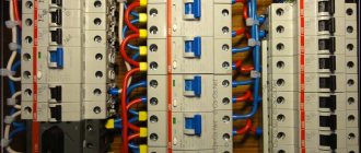
The distribution panel is mounted on the wall. An input cable is connected to it from under the floor. Further connections to the machines will take place inside the panel. At the points where branches exit to sockets, switches and lighting devices, cable outlets 200 mm long are left from under the floors. Distribution boxes are installed here. All further connections occur in the same way as when laying the cable in the walls.
Ceiling cable routing
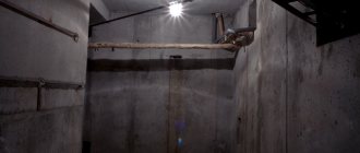
Things are simpler in panel houses. Many electricians lay cables inside the voids of interfloor slabs. Most often, room lighting lines are placed here. To avoid cutting grooves, a branch from the wall is pulled through the void of the slab and the wire is released from a drilled hole in the center of the ceiling to connect the lighting fixture.
Inside the ceiling, you can organize a common line, then only branches for sockets and switches will go to the walls. At the places where the cable turns and where the wires are connected in the junction box, an outlet of a maximum of 150 mm from the ceiling is made at a right angle.
Codes of Practice (SP)
| Set of rules | Name of the regulatory document | Download |
| SP 9.13130.2009 | Fire equipment. Fire extinguishers. Operating requirements | |
| SP 437.1325800.2018 | Low-voltage electrical installations of buildings and structures. Rules for designing protection against electric shock | |
| SP 256.1325800.2016 | SP 256.1325800.2016 Electrical installations of residential and public buildings. Rules for design and installation (with Amendments No. 1, 2, 3) |
Installation of open electrical wiring
The essence of open installation is to lay the cable in special boxes. This is done only on the walls and ceiling. Work begins with the same layout of the room. Boxes are attached to the drawn lines using dowels and self-tapping screws at 500 mm intervals. External distribution boxes are installed opposite the branches. Sockets and switches are also used only externally. Connecting all the wiring occurs in exactly the same way as for hidden wiring, only here you do not need to cover the grooves with plaster. The boxes with the cable inside are closed with decorative covers.
Guiding Documents (RD)
| Guidance document | Name of the regulatory document | Download |
| RD 153-34.0-20.262-2002 | Rules for the use of fire-retardant cable coatings at energy enterprises | |
| RD 34.21.122-87 | Instructions for the installation of lightning protection of buildings and structures | |
| RD 34.20.182-90 | Guidelines for standard protection against vibration and suboscillations of wires and lightning protection cables of overhead power lines with voltage 35-750 kV |
Methods for installing sockets and switches
Depending on the type of wiring, external or built-in sockets and switches are used. External models are simply screwed to the wall with self-tapping screws or glued with glue. Under the built-in models, a recess is cut out in the wall with a crown, inside which the socket box is fixed with plaster. The socket or switch in the socket box is fixed with a clamping mechanism.
By following the rules for installing electrical wiring, almost all work can be done at home yourself. But if there are any doubts, it is better to consult with specialists.
Some gasket features
- Wires or electrical cables can be laid in rows individually, in bundles, in bags or in multilayers. When laying wires in rows in one layer, the recommended clearance between adjacent wires is five millimeters. When laying in bunches or packages, the gap increases to 20 mm; when laying in multi-layers, no gap is allowed at all.
- When laying wires in bundles, it is necessary to ensure that there are no more than twelve wires in one bundle, and the diameter of one bundle should not exceed 10 cm.
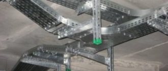
- When laying wires horizontally on cable trays, it is recommended to tie them into bundles with a pitch of at least 4.5 meters. At the same time, in straight horizontal sections it is allowed not to tie the wires into bundles at all. When laying wires vertically in mounting boxes, the minimum linking step is 1 meter.
- After the metal structure of the cable-supporting route has been assembled and secured to the floors of the building with a special cord, the length of the route is measured for measuring cutting of electrical cables and wires. After cutting, the wires are grouped into bundles, bandaged and equipped with marking tags. After laying the electrical wires in trays and boxes and connecting them into a single circuit, the “phase-zero” continuity is checked and the insulation resistance is monitored with an ohmmeter.
- Laying of wires in cable trays and ducts must be carried out at a certain temperature. At ambient temperatures from -15°C and above, it is permissible to lay cables without preheating them. In the temperature range -40...-15°C, cables and wires must be preheated before laying. At air temperatures of -40°C and below, cable laying is prohibited.
- Electrical cables and wires are laid in electrical boxes with a reserve length necessary to compensate for temperature deformations and possible soil displacements. The electrical cable supply must be laid straight. Laying the stock in rings or coils is not allowed.
- When laying cables and wires openly in plastic or metal cable ducts, their possible heating under the influence of solar radiation should be taken into account. In this case, sun screens are additionally provided.
- Any cable line must be as complete as possible (laid in entire construction lengths), that is, have a minimum number of couplings.
- Electrical cables, regardless of the design of the supports, must be fastened at the end points, at connecting or end couplings and at turns of the highway. It is recommended to fasten straight sections of the cable route in increments of 1.0-1.5 meters. When laying wires in bundles, the fastening pitch can be increased to 8-10 meters.
- Installation of an electrical cable must prevent possible deformations from: • the cable's own weight; • mechanical stresses that arise from cyclic heating and cooling; • magnetic interactions that occur during short circuits.
- When crossing a cable route with a pipeline, the distance between the cable trays and the pipeline must be at least 5 cm. If they are located parallel, the minimum distance increases to 10 cm. If gas or flammable liquid is transported through the pipeline, the shortest distance to the cable tray is taken to be 25 cm .
- When laying electrical wires in a cable tray, for ease of maintenance in future operation, as well as for natural cooling purposes, it is recommended to fill no more than 50% of the volume of the electrical box.
- When organizing a cable route using cable trays and ducts, you should ensure that during installation the individual elements have reliable metal contact with each other, since usually only the beginning and end of the cable support system (or one branch) are grounded.
- Cable trays and ducts are mounted at a height of at least two meters from the floor or service area. In rooms where only specially trained personnel can work (for example, in electrical rooms), installation of metal trays at any height is allowed.
- The method of installation of electrical boxes and trays must exclude the possibility of moisture accumulation in them. For open laying of cables and wires, boxes with a removable lid are usually used to ensure easy access. For hidden wiring, the use of pipes and “blind” boxes for wires is allowed.