The internal network includes electrical wiring and electrical installation devices located inside the building. Correct calculation of the load is the main condition for design. If installation rules are violated, an emergency situation occurs that leads to a fire.
Internal electrical networks equipment for buildings Internal electrical networks equipment for buildings
Source:
https://minenergokbr.rf
Why is it necessary to draw up electrical network diagrams?
Electrical wiring is a complex undertaking that requires professional skills. Therefore, operations are performed by qualified specialists. For wiring, a drawing is drawn up containing all objects that relate to electricity. Key objects include:
- switches;
- sockets;
- lighting;
- electric brushes with residual current devices (RCDs).
Specialists draw up diagrams of the building's electrical networks, taking into account the wishes of the customer and the individual features of the building's layout. The main job is to separate the cables into separate, efficiently functioning lines. The task is to correctly distribute loads and organize a system for controlling and protecting electrical wiring.
Before drawing up a drawing and plan, study the features and purposes of each individual component element. Circuit breakers that help protect networks from overloads are located in electrical panels. The functioning of the electrical network and safety directly depend on correct installation.
Wires that conduct current to different points are carefully selected. The choice of section is made individually. Reliable contacts are selected for switches and sockets.
Residual current device (RCD)
Source: https://vyborok.com
External network design process
High-quality design of external power supply lines involves the implementation of design and calculation work in accordance with current regulatory documents, as well as various standards of departments and organizations that control the electrification process.
Only experienced specialists who understand the specifics of current regulations and their requirements can carry out such work.
The laying of external power supply networks is carried out on the basis of an electrical project, which includes many different design documentation, various diagrams, drawings, calculations, estimates and other data necessary for electrical installation work. At its core, a complete power supply project includes several separate small projects, which form the general features of the future electrical system.
Why apply standards?
To avoid dangers when installing electrical networks, correctly calculate the cross-sectional area of the wire, which is responsible for the resistance. The higher it is, the more the cable heats up. Proper selection plays an important role:
- cable material;
- wire connections;
- selection of installation location;
- insulating material.
It is important to correctly calculate the load, select protective devices and install grounding.
If you do not apply the standards established by law, errors will lead to a short circuit and a fire. If the rules are not followed, the insurance company will not pay insurance in the event of an accident.
Electrical network project
For residential and industrial buildings, an electrical network design is drawn up, which contains:
- wiring diagram;
- list of required materials.
The diagram shows the places for the connections:
- power cables;
- scutes;
- distribution boxes;
- lighting fixtures;
- socket boxes;
- switches;
- sockets;
- other materials intended for energy consumers.
At the design stage, the required network power is calculated, since the choice of electrical equipment for the entire system depends on the planned load.
If the calculations are made incorrectly, the electrical network will work unstably with problems and disturbances. The design takes into account that the maximum power consumed by a certain group of devices is always less than the total power ratings of the receiving devices.
This is due to the fact that equipment does not always work at full capacity, so the highest load level rarely coincides with time. Therefore, this factor must be taken into account in the process of organizing the electrical network system and choosing the component elements.
Electrical network diagram
Source: https://ppt-online.org
Cable selection and RCD use
To ensure the safety of electrical networks, RCD fire-fighting devices are installed in buildings and certain values are set on the device. In a residential building, the leakage current for common lines is set to 100 mA. Individual lines have a minimum value of 10 mA. When the indicator increases, the residual current device (RCD) de-energizes the building.
Electrical wiring is carried out using safe cables approved by GOST. Aluminum wire is not used for the internal electrical network. It is used to supply electricity to the house. The most preferred option for internal wiring is copper cable. Its advantages include:
- high current density;
- fracture toughness and good wear resistance;
- has little resistance to oxidation;
- Compared to aluminum, it does not compress, so there are no gaps in the joints.
The budget option includes the VVG brand. There are also other types with different properties:
| Cable brand | Purpose |
| Incombustible | Reduced gas and smoke emissions. |
| VVGng with three cores of 6 mm2 each. | For cable ducts in residential buildings. |
| VVGng (3x2.5) | For hidden box on sockets and distribution boxes. |
| VVGng (3x1.5) | Connected to lighting fixtures and switches. |
| PV1 | For electrical panel. |
| PVS (3x2.5) | For electrical appliances. |
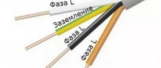
For internal stationary wiring, single-core copper wire is most often used, since it is more reliable and durable than its multi-core counterpart.
Cables for internal electrical network
Source: https://yato-tools.ru
Selecting a laying method
The choice of method for laying the electrical network is influenced by:
- place;
- environmental conditions;
- building size;
- wire section;
- network diagram.
Environmental influence:
- destroys the insulation of electrical equipment;
- poses a danger to operating personnel;
- provokes explosions and fires.
The insulation of wires, live parts and structures is destroyed by moisture, gases, caustic vapors and elevated temperatures. Because of this, a short circuit may occur, and a dangerous impurity may form in the air, leading to explosions and fires.
The location of the electrical line affects the installation method, safety, ease of work and operation.
Cable installation methods
The method of laying the wire is influenced by the category and material of the building, as well as the type of electrical wiring. There is an open, closed, underground method.
Open
Exposed electrical wiring is a simple method of laying wire. The advantages include ease of cable repair if damaged and ease of replacement.
This method is used when there are no other options. During the work they use:
- cable channels (mounted on any structure);
- boxes.
In industrial buildings, warehouses and utility rooms, cable ducts are replaced with corrugated pipes, since aesthetics are not required in these rooms.
Open wiring is allowed in buildings built from combustible material belonging to groups G2 and G3. It is allowed to use a cable with a copper core and a PVC protective sheath.
Open method of laying an internal electrical network
Source: https://imnz.ru
Closed
In residential buildings, closed wiring is usually used, which consists of a network of cables and wires embedded in the walls using pre-prepared grooves. Walls made of non-flammable or slightly flammable material are suitable for gating:
- concrete;
- bricks;
- foam block;
- cinder concrete.
It is forbidden to make holes for cables in ceilings and floors without appropriate permission and calculations. The closed method is the safest, since the wires are completely protected from mechanical action.
Hidden electrical wiring is carried out with cables equipped with a protective sheath. The wire laid in the floor is protected with electrical corrugation. For example, the VVGng wire has double insulation, and the NUM wire has triple insulation. They are allowed to be walled into the wall without the use of corrugation and pipes.
There is retractable electrical wiring. This means that in case of emergency cable damage it can be replaced. Electrical wiring is carried out in a plastic or polyethylene pipe. It will not be possible to pull the wiring through the corrugation.
Closed method of laying an internal electrical network
Source: https://esm62.ru
Combined
The combined method is a combination of a closed and open gasket. The method helps to simplify the installation of the electrical network. According to standards, boxes are chosen from plastic, since the material is practical and reliable. Free space is left inside, which makes it possible to hide the necessary wires.
To prevent the wall from igniting due to a short circuit, an insulating layer is used. For example, according to the standard, the thickness of asbestos is made at least 0.5 cm.
Vertical walls
Panel buildings have prepared grooves, which are made at the factory, since concrete has a high hardness index. Holes cannot be made in wooden walls. In addition, hidden wiring must not be laid in flammable materials. In this case, additional protection for cables and wires is used in the form of plastic materials and corrugated pipes.
For flammable materials, it is recommended to use steel pipes with grounding. The passage in the wall is protected with a piece of pipe.
Rules for laying wires
Regardless of the chosen method of laying cables, certain rules and regulations are observed:
- to minimize the occurrence of problems during the installation process, the wires are laid out in a strictly vertical or horizontal position;
- horizontal sections are placed at intervals of 150-200 mm from the ceiling;
- The wires should not touch each other;
- the vertical section is prohibited from being placed near corners, door and window openings (the minimum permissible value is 100 mm);
- Maintain a distance of 40 cm from gas pipes.
The rules for installing electrical networks are described in GOST R 50571.5.52-2011.
Rules for laying wires
Source: https://seaside-home.ru
Price list for laying power supply networks in Moscow
| List of materials, equipment and works | Qty | Unit change | Price |
| Cable VVGng-Ls 2x1.5 | 1 | m. | 40 rub. |
| Cable VVGng-Ls 3x1.5 | 1 | m. | 50 rub. |
| Cable VVGng-Ls 3x2.5 | 1 | m. | 50 rub. |
| Cable VVGng-Ls 3x4 | 1 | m. | 70 rub. |
| Cable VVGng-Ls 3x6 | 1 | m. | 80 rub. |
| Cable VVGng-Ls 3x10 | 1 | m. | 100 rub. |
| Cable VVGng-Ls 4x1.5 | 1 | m. | 60 rub. |
| Cable VVGng-Ls 4x2.5 | 1 | m. | 60 rub. |
| Cable VVGng-Ls 5x2.5 | 1 | m. | 70 rub. |
| Cable VVGng-Ls 5x4 | 1 | m. | 80 rub. |
| Cable VVGng-Ls 5x6 | 1 | m. | 90 rub. |
| Cable VVGng-Ls 5x10 | 1 | m. | 110 rub. |
| Cable VVGng-Ls 5x16 | 1 | m. | 130 rub. |
| Cable VVGng-Ls 5x25 | 1 | m. | 150 rub. |
| Cable VVGng-Ls 5x35 | 1 | m. | 170 rub. |
| Cable VVGng-Ls 5x50 | 1 | m. | 180 rub. |
| Cable VVGng-Ls 5x70 | 1 | m. | 200 rub. |
| Cable VVGng-Ls 5x95 | 1 | m. | 220 rub. |
| Cable VVGng-Ls 5x120 | 1 | m. | 250 rub. |
| Cable VVGng-Ls 5x150 | 1 | m. | 300 rub. |
| Wire PV3 (1x2.5) | 1 | m. | 20 rub. |
| Wire PV3 (1x4) | 1 | m. | 30 rub. |
| Wire PV3 (1x6) | 1 | m. | 40 rub. |
| Wire PV3 (1x10) | 1 | m. | 50 rub. |
| Wire PV3 (1x16) | 1 | m. | 60 rub. |
| Wire PV3 (1x25) | 1 | m. | 70 rub. |
| Wire PV3 (1x35) | 1 | m. | 90 rub. |
| Wire PV3 (1x50) | 1 | m. | 110 rub. |
| Wire PV3 (1x70) | 1 | m. | 130 rub. |
| Wire PV3 (1x95) | 1 | m. | 150 rub. |
| Wire PV3 (1x120) | 1 | m. | 180 rub. |
| Crimping, marking and connection of conductors up to 4 sq. mm | 1 | PC. | 100 rub. |
| Crimping, marking and connection of conductors up to 16 sq. mm | 1 | PC. | 160 rub. |
| Crimping, marking and connection of conductors up to 50 sq. mm | 1 | PC. | 180 rub. |
| Crimping, marking and connection of conductors up to 120 sq. mm | 1 | PC. | 220 rub. |
| Crimping, marking and connection of a 185 sq.m. core. mm | 1 | PC. | 300 rub. |
| All-metal tray, width 50 mm | 1 | m. | 150 rub. |
| All-metal tray, width 100 mm | 1 | m. | 200 rub. |
| All-metal tray, width 150 mm | 1 | m. | 250 rub. |
| All-metal tray, width 200 mm | 1 | m. | 300 rub. |
| All-metal tray, width 300 mm | 1 | m. | 350 rub. |
| All-metal tray, width 400 mm | 1 | m. | 400 rub. |
| Partition for tray | 1 | m. | 70 rub. |
| PVC corrugated pipe d=16 mm | 1 | m. | 30 rub. |
| PVC corrugated pipe d=20 mm | 1 | m. | 30 rub. |
| PVC corrugated pipe d=25 mm | 1 | m. | 40 rub. |
| PVC corrugated pipe d=32 mm | 1 | m. | 60 rub. |
| PVC corrugated pipe d=40 mm | 1 | m. | 80 rub. |
| PVC corrugated pipe d=50 mm | 1 | m. | 90 rub. |
| PVC corrugated pipe d=63 mm | 2 | m. | 110 rub. |
| Cable channel 16 mm wide | 1 | m. | 100 rub. |
| Cable channel 25 mm wide | 1 | m. | 120 rub. |
| Cable channel 40 mm wide | 1 | m. | 140 rub. |
| Cable channel 60 mm wide | 1 | m. | 180 rub. |
| Cable channel 80 mm wide | 1 | m. | 220 rub. |
| Cable channel 100 mm wide | 1 | m. | 260 rub. |
| Cable channel 150 mm wide | 1 | m. | 290 rub. |
| Installation of a socket box on concrete | 1 | PC. | 160 rub. |
| Installing a socket box on a brick | 1 | PC. | 160 rub. |
| Installation of a socket box on plasterboard | 1 | PC. | 120 rub. |
| Drilling a hole Ø 68 mm in concrete | 1 | PC. | 400 rub. |
| Drilling a hole 68 mm in brick | 350 rub. | ||
| Drilling a hole 68 mm in gypsum board | 1 | m. | 240 rub. |
| Strobe for concrete | 1 | m. | 450 rub. |
| Brick groove | 1 | m. | 420 rub. |
| Strobe on foam block | 1 | m. | 320 rub. |
| Punching holes in concrete | 1 | m3 | 32,000 rub. |
| Punching holes brick | 1 | m3 | 18,000 rub. |
| Installation and connection of the lamp | 1 | PC. | 1,200 rub. |
| Installation and connection of the emergency power supply of the lamp | 1 | PC. | 600 rub. |
| Installation and connection of a bactericidal indicator | 1 | PC. | 800 rub. |
| Installation and connection of a bactericidal lamp | 1 | PC. | 1,600 rub. |
| Installation and connections of the socket | 1 | PC. | 350 rub. |
| Installation and connections of the grounding socket | 1 | PC. | 350 rub. |
| Installation and connections of the switch | 1 | PC. | 350 rub. |
| Installation and connection of pass-through switch | 1 | PC. | 400 rub. |
| Installation and disconnection of distribution boxes | 1 | PC. | 300 rub. |
| Installation and disconnection of the PMC | 1 | PC. | 400 rub. |
| Installation and connection of the ground clamp | 1 | PC. | 250 rub. |
| 3ph motor connection | 1 | PC. | 1,200 rub. |
| Installation of circuit breaker 1p up to 63 A with disconnection | 1 | PC. | 350 rub. |
| Installation of a 2p circuit breaker up to 63 A with disconnection | 1 | PC. | 450 rub. |
| Installation of a 3p circuit breaker up to 63 A with disconnection | 1 | PC. | 550 rub. |
| Installation of a copper busbar measuring up to 4x40x300 mm (TxWxD) as "L", "N", "PE" busbars | 1 | PC. | 500 rub. |
| Installation of a cross-module with connection - 2 buses | 1 | PC. | 400 rub. |
| Installation of a cross-module with connection - 3 buses | 1 | PC. | 600 rub. |
| Installation of a cross-module with connection - 4 buses | 1 | PC. | 800 rub. |
| DIN Rail Installation | 1 | m | 60 rub. |
| Installation of a switchboard for 12 modules (with “N” and “PE” buses) | 1 | PC. | 2,000 rub. |
| Installation of a switchboard with 24 modules (with “N” and “PE” buses) | 1 | PC. | 3,000 rub. |
| Installation of a switchboard for 36 modules (with “N” and “PE” buses) | 1 | PC. | 4,000 rub. |
| Installation of a panel on 54 modules (with “N” and “PE” buses) | 1 | PC. | 5,000 rub. |
| Installation of IT shield (standard) | 1 | PC. | RUR 2,500 |
| Installation and connection of an isolation transformer into the IT panel housing | 1 | PC. | 800 rub. |
| Installation of metering cabinet SHU-1T | 1 | PC. | 3,000 rub. |
| Installation of the SHU-2T metering cabinet | 1 | PC. | RUB 5,200 |
| Installation of main switchgear for 10 connections | 1 | PC. | RUB 3,200 |
| Installation of grounding strip steel 4*40mm | 1 | m. | 500 rub. |
| Installation of grounding strip copper 5*50mm | 1 | m. | 600 rub. |
| Installation of the connecting sleeve | 1 | PC. | 80 rub. |
| Installation of deep grounding | 1 | m/n | 1,200 rub. |
| Installation of lightning protection wire | 1 | m/n | 300 rub. |
| Installation of a 4 Ohm ground loop | 1 | PC. | RUB 7,600 |
| Connecting a 3ph heat gun | 1 | PC. | 500 rub. |
| Installation of end coupling | 1 | PC. | 1,500 rub. |
| Installation of a through coupling | 1 | PC. | 6,000 rub. |
Compliance with standards
When installing electrical networks, comply with the requirements set out in the standards. The main conditions include:
- when installing internal electrical networks, they are guided by the requirements of the Electrical Installation Rules;
- calculations of the compliance of the cross-section of a current-carrying wire are regulated by GOST;
- open cable routing without the use of insulation is located at a height of less than two meters to prevent burns;
- In attic spaces, wires sheathed in fireproof materials are used.
If there are damp and damp places in the building, then cable laying is kept to a minimum. The passage of wires between floors is carried out in pipes. However, they should not be twisted. Single-pole switches are used for lighting.
A common cause of fire is incorrect connection of wires. To avoid problems, the joints are soldered or welded.
What documents should you rely on when installing power electrical equipment?
When installing power electrical equipment, you need to rely on a number of regulatory documents. The main ones:
- GOST 21.613-2014 “System of design documentation for construction (SPDS). Rules for the implementation of working documentation for power electrical equipment";
- “Rules for electrical installations”;
- GOST R 50012-92 “Electromagnetic compatibility of technical equipment. Power electrical equipment. Methods for measuring parameters of low-frequency periodic magnetic field";
- GOST 30331.1-95 (IEC 364-1-72, IEC 364-2-70) “Electrical installations of buildings. Basic provisions";
- GOST R 50571.2-94 “Electrical installations of buildings. Part 3. Main characteristics."
To order installation of power electrical equipment, call us by phone or send a request by email - we will be happy to advise you!
Order
Professionals know the specifics of creating an internal electrical network, which differs depending on the features of the facility. When ordering turnkey work from a master:
- lay cable lines and wires;
- install electrical equipment;
- connect switches and sockets;
- install lighting fixtures;
- install alternative power supply systems;
- test and replace electrical wiring and failed elements.
First of all, specialists conduct a site survey and develop technical specifications based on the client’s preferences. Then:
- prepare a design for internal electrical networks;
- select suitable electrical equipment;
- install electrical wiring and installation products;
- carry out commissioning work;
- prepare the necessary documentation;
- provide guarantees for installation work for several years;
- obtain permits to use the facility’s electrical network;
- carry out maintenance after installation is completed.
Specialists plan expenses and calculate the cost of work. The price depends on the quantity and complexity of installation work and the type of electrical equipment used.
Installation work
External electrical installation work can be carried out during reconstruction, repair of old electrified facilities and substations, when laying overhead power lines, when installing new lighting poles, grounding systems and in other situations.
If it is necessary to organize external networks for the electrification of various structures, as well as to organize external lighting systems, electrical installation may include the following work:
- Development of a high-quality electrical project, including design of electrical circuits, carrying out the necessary calculations and drawing up estimates for installation.
- Construction of new transformer substations.
- Installation of power lines for the power supply system.
- Creation of an external lighting system with the installation of various lighting equipment.
- Creation of poles for outdoor lighting.
- Laying cable lines for external power supply.
- Connecting various objects to power from existing transformer substations.
- Coordination of prepared project documentation with regulatory government agencies.
Electrical network of a public building
The electrical network diagram in a public building indicates:
- significant share of power electrical receivers;
- specific operating mode;
- the possibility of integrating transformers into public buildings;
- other requirements for room lighting.
When power consumption exceeds 400 kW, it is recommended to use a built-in substation. The benefits include:
- saving of non-ferrous metals;
- exclusion of laying an external cable line up to 1 kW;
- there is no need for separate ASU devices in buildings, since they can be connected to the 0.4 kW switchgear of the substation.
The substation will be located on the ground or technical floor or in the basement. If the building has a freight elevator, it is allowed to be installed on the middle or top floor.
According to standards, the group distribution board of the lighting network is required to be located on the staircase or in the corridor. Outgoing lines are:
- single-phase;
- two-phase;
- three-phase.
Preference is most often given to a three-phase group line, which provides 3 times the load and 6 times less voltage loss (compared to single-phase).
Electrical network of a public building
Source: https://panelektrik.ru
Types of power electrical equipment
Power electrical equipment can be classified according to a number of characteristics:
- According to its intended purpose, it can be domestic or industrial.
- By voltage – low-voltage (up to 1,000 V) and high-voltage (over 1,000 V).
- By design - stationary and mobile.
- By design - individual and complete.
- By location - built-in and free-standing.
Power equipment
Stages of cooperation with us
Call/Request
Calculation of cost of services
Signing the contract and starting work
Download detailed price list
for all our services for repair and finishing work and comprehensive maintenance of real estate
Material calculation
After preparing the electrical network diagram, the necessary materials are calculated. First of all, calculate the footage of cables that supply electric current and are responsible for the functioning of devices in normal mode.
When calculating the length of the wires, the following factors are taken into account:
- number of planned switches and sockets;
- number of lighting fixtures;
- place of installation of electric meters and transformers.
Then, using a construction tape, measure the distance from the distribution box to all electrical points. The data obtained is recorded in terms of electrical network wiring. The indicators are added together. Approximately 15% is added to the total quantity for reserve, since an unforeseen situation may arise during the installation process.
During operation of the electrical network, the wires heat up. Therefore, it is prohibited to place them in one place in large quantities. It is required to comply with the standards prescribed by regulatory documents governing electrical networks. Often during installation they arrange parallel wiring with turns and bends.
After calculating the required number of wires, calculate the required number of other materials:
- switches;
- distribution boxes;
- lighting fixtures;
- protective tubes;
- fastenings;
- terminal blocks;
- cable channels.
Correct calculation simplifies the installation of electrical networks in residential and industrial buildings.
Rules for the internal electrical network
During installation of the electrical network, follow the rules:
- Cable entry into the building is carried out in pipes. They are located at a depth of 0.5 meters and no more than two meters from the surface of the earth. One power cable is pulled into the pipe.
- It is allowed to lay power cables and busbars with a voltage of no more than one kW through the technical underground in sections of the building and the basement.
- The pipe is laid with a slope towards the street. When laying through walls, the end of the pipe is carefully sealed to prevent gas and moisture from entering the room.
- It is prohibited to lay transit electrical wiring through the warehouse and storeroom.
It is not recommended to place electrical wiring in the escape route. If this requirement cannot be met, then the electrical wiring is protected with a sheath or casing, which prevents the occurrence of fire and the spread of fire. Wiring along the evacuation route is located in as small an area as possible. In this case, the wires should not be within reach of your hands. Otherwise, they are protected from mechanical damage that occurs during evacuation.
Rules for the internal electrical network
Source: https://renrus.ru
Rules for introducing electricity into a building
Most often, electricity is introduced into a building using a self-supporting SIP wire. Additional poles to support the cable are not required if the power line support is located at a distance of up to 25 meters.
The wire is pulled to the electrical panel, in which the RCD, circuit breakers are located and the ground loops are connected. The transition to the VVGng cable is carried out in another panel with a metering device.
When entering, comply with the following requirements:
- If the wire length is more than 25 meters, then additional support is installed. To do this, a shield is installed on the nearest pole, and a ground loop is buried in the ground. The wire between the supports is stretched at a height of at least two meters above the ground.
- If cables cross building structures, they are installed in protective pipes.
- The minimum permissible distance from the ground to the building connection point is 2.75 meters.
- If the wire is pulled underground, it must first be placed in a protective sheath. Then they will place it in a ditch, the depth of which should be at least 0.7 meters.
The underground installation of the input is provided at the time of construction of the building and the energy supply project is prepared. Technical documentation is drawn up according to the rules. Therefore, drawings should be developed by specialists with experience in this field.
It is necessary to correctly determine the brand of cable and calculate the cross-section of the current-carrying wires. To sign an energy supply project, certain technical conditions are met, including obtaining permission to carry out excavation work, which is approved by the services responsible for:
- communication and power transmission systems;
- buildings and constructions;
- gas pipeline;
- heating mains;
- green spaces;
- water pipes;
- roads;
- sewer pipes.
If communications are located near the proposed cable laying site, then contact the responsible organizations to coordinate the location of the trenches and to control the work being carried out.
For underground installation, armored cables are used. It is forbidden to lay them in metal pipes along their entire length, since when filled with groundwater in the winter, the resulting ice will damage the wires.
Input of electricity into the building
Source: https://muchenergy.ru/
Overhead cable channels
The overhead or suspended type of laying external power supply networks is considered the simplest and most affordable. This option involves placing a cable over the air from the nearest pole to the electrified object. This technique is best suited for owners of private houses, the distance from the facades of which to the nearest pillar is less than 20 meters. If this distance is large, then the installation of an additional support is required to organize the air input.
When electrifying private houses, the cable is brought through an overhead line to the external wall of the building, where it is securely fixed. Near the place where the cable is supplied to the wall there is an electrical panel in which a meter for metering electricity consumption is located. To ensure a reliable connection, when connecting several buildings located nearby, it is customary to use special supports.
All the work described above can only be carried out by professional electricians and with the appropriate permission from the operating company.
Below you can use the online calculator to calculate the cost of electrical installation work.
Permission to operate the electrical network
To obtain permission to use the internal electrical network, it is necessary to submit design documents to the Electric Networks branch to check for compliance with the requirements of technical legal acts. Employee:
- will check the completed installation of the electrical installation for compliance with the current operating rules and the project;
- will provide instructions on electrical safety during operation of the electrical network;
- will check whether the results of the electrophysical measurement comply with the requirements of technical regulations.
After the inspection, the employee will draw up an inspection report and issue a conclusion on the possibility of supplying voltage to the electrical installation or indicate any identified violations that need to be corrected.
When installing an internal electrical network, it is important to correctly calculate the voltage and select the appropriate type of cable. It is necessary to consider whether power sources will be installed on the building for lighting advertising, shop windows, facades, as well as external and fire protection devices. Incorrect installation of the electrical network will disrupt the operation of the system and lead to a fire.
tags: ELECTRIC POWER SUPPLY ELECTRICAL NETWORKS ELECTRICAL NETWORKS
Laying power cable underground
If installation of an overhead line is not possible, then the cable is laid underground. For this purpose, special channels or trenches are created. The calculation of their width and depth is carried out within the framework of the power supply network project, depending on the power of the line and the number of cables to be laid. Stages of work:
- Marking.
- Creating a trench.
- Preparing the trench for laying wires - if necessary, the walls are concreted, or ready-made concrete elements are installed.
- Filling the trench with sand to create a sand cushion to level out soil movement and subsidence.
- Laying cables.
- Covering with a slab and digging the trench.
In order for the power facility to be safe and meet regulatory requirements, an appropriate design must be prepared in advance. It must take into account the location of other utility networks and the distances to them. Order a project from our engineers and receive documentation completed at a high technical level, this is guaranteed by the extensive experience and professionalism of our employees.

