STANDARDS AND REQUIREMENTS TYPES AND TYPES OF TRAYS
Tray placement of cable routes is implemented mainly in industrial premises and requires a special approach to the selection of structures and compliance with PUE standards during their design and installation.
Particular attention is paid to dissimilar lines and electrical circuits; deviation from safety requirements when placing them in trays is fraught with serious failures and risks of electrical installations failing.
IN WHAT CASES IS CABLE LAYING IN TRAYS USED?
A tray is an open fireproof structure used for laying cables and wiring inside buildings and in outdoor installations.
In particular, according to the PUE standards, insulated, but without special armor, cables with a voltage of up to 1000 V and a cross-section of up to 16 mm2 are laid in them.
The upper limit of the cross-section and reliability of insulation is not limited; the use of trays is permissible for all cases of open installation, unless the rules stipulate otherwise (namely, mandatory installation in blind steel pipes).
This method is recommended to be chosen if necessary:
- open laying of a large number of wires in dry, damp or hot industrial premises (with the mandatory placement of the tray 2-2.5 m above the floor level and service area, depending on the requirements of the PUE clause 2.1.52);
- placing the cable in rooms with a chemically active or fire hazardous environment (unless the rules stipulate otherwise);
- laying wires and cable systems on vertical and horizontal sections of technical floors, in passages behind switchboards and transitions between them, basements of electrical machine rooms, in compressor and pump rooms.
The main advantages of this method include ease of maintenance and good preservation of the cable sheath (the product is not pulled through pipes and wears less, finding and replacing damaged areas is simplified).
Protection from external influences is not the main goal of installing trays, but it is still achieved to one degree or another.
Trays provide organized routing and cooling of large accumulations of wires and remove them at a safe distance from aggressive environments, heat sources or dangerous devices. Laying branches is possible at any site; with an increase in the number of wires and their presentation in trays, no problems arise.
The disadvantages are manifested in labor intensity and an increase in cost by at least 2 times in comparison with securing the cable to structures without the use of protective structures.
But in comparison with installation in pipes and other options chosen for high fire and moisture protection requirements, this method is cheaper.
The limitations taken into account also include the need for combination with other (closed) laying methods when organizing the lowering of trays to distribution boards.
Rules for laying cables in trays
When in industrial premises the number of wires and cables laid along common routes is very large, it is advisable to use cable routing on trays. Trays are intended for:
- open laying of cables in dry, damp and hot rooms;
- rooms with a chemically active environment;
- fire hazardous premises for laying wires and cables permitted for such premises;
- cable mezzanines and basements of electrical machine rooms;
- passages behind shields and panels of control stations and transitions between them;
- technical floors of buildings and structures.
This electricity drainage system is highly flexible and greatly simplifies installation and operation. Wiring in trays provides good cooling conditions for cables, provides greater savings and reduces the cost of work compared to other types of wiring.
When using trays, it is easier to carry out wiring on complex routes; it is possible to arrange a branch on any section of the tray line route.
Unarmored cables with a voltage of up to 1 kV with a core cross-section of up to 25 mm2 can be laid in trays in multi-layers, in bundles and single-layers without gaps. The height of cable layers laid in multilayers should be no more than 150 mm. The height (diameter) of the beam should be no more than 100 mm. The distance between bundles of power cables must be at least 20 mm; The distance between bundles of control cables, as well as power and control cables, is not standardized.
Installation of a low current
Only highly qualified professionals can install a low-current network quickly and efficiently. The work process may include the following components:
- laying various information networks (telephone, television, computer, Internet cables);
- installation of information sockets and other elements of specialized equipment;
- installation of various communication devices (intercoms, alarm systems and video surveillance).
The presence, structure and distance of external low-current systems affects the installation features and the cost of the work of the craftsmen. As for interior installation, it can be done in various ways depending on the decorative elements and characteristics of the room. The most commonly used methods are:
- Installation in wall cavities is convenient if the house has a frame structure or the walls are made of plasterboard. This way you can completely hide the wiring and it will not disturb the appearance of the room, since it will be completely hidden from view in the walls.
- Installation of low-current systems in channels allows you to protect the cable from mechanical stress by hiding them in pipes of the appropriate diameter. These pipes can be hidden using interior and decorative elements.
- Laying in the cavity of a suspended ceiling also completely frees the room from the type of wiring. It is especially convenient for commercial systems in premises where all rooms are equipped with suspended ceilings.
- Installation into a raised floor is convenient for major renovations or construction of a building. This method allows you not only to hide the wires, but also to install information sockets in the floor, which is very practical for using mobile partitions in offices.
- Laying wiring in the air is used to install an external low current between houses.
- Underground installation is used when laying external low-current networks. It provides connection between buildings.
During the installation process, all these methods can be combined with each other to achieve the best result and long-term network service. In domestic conditions, it is even possible to install using different methods in separate rooms. This allows you not to violate the integrity of the appearance of the premises and at the same time supply them with the necessary equipment for the full operation of the information network and uninterrupted communication.
Tags: machine, ampere, beat, sconce, view, choice, house, , ground, cable, how, computer, design, , installation, load, voltage, rule, wire, wiring, laying, start, , work, relay, repair , row, garden, network, system, connection, term, ten, type, current, facade, shield, effect
Additional features
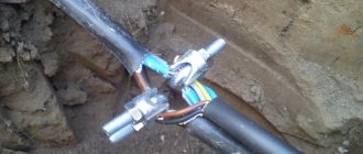
If we talk about the process of grounding cable trays itself, some companies recommend doing it at intervals of twenty meters. However, according to experts, grounding should be done every ten meters. Such grounding is used when the structure is operated in unfavorable conditions.
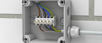
For correct and reliable connection to the cable holder, it is recommended to use special and sometimes reinforced terminals. They are sold in almost all markets or construction hypermarkets. Installation is very simple. First, you need to attach the terminal to the side wall of the tray, then pass the cable through its hole. At the point where the wire contacts the hole, the insulation should be stripped from the terminal.
Now you know how cable trays are grounded and what requirements need to be taken into account when organizing this type of protection. We hope the information was useful and understandable for you!
How to calculate the load capacity of trays?
Having determined the occupancy level of the cable trays, you can begin to calculate their load capacity. There are 3 main methods for this: experimental, formulaic or calculation according to the manufacturer. The most expensive is the experimental method. Therefore, a formulaic calculation is most often used, taking into account the requirements of the DIN VDE 0639 standard. It is worth adding that the level of load capacity of cable trays directly depends on their occupancy rate.
Normative documents
The laying of cables and wires must be carried out in accordance with the project, special instructions, as well as taking into account the requirements of current regulatory documents: - SNiP 3.05.06-85 “Electrical devices”; — GOST R “Electrical installations of buildings. Part 5. Selection and installation of electrical equipment”, Chapter 52 “electrical wiring”; — “Rules for electrical installations.”
These norms and rules must be followed both at the design stage and directly during installation work of the cable support system.
The main task of the installers is to assemble a system of cable trays and boxes and lay electrical cables and wires in them in strict accordance with the electrical design. The design, material and degree of protection of cable-supporting elements, as well as the method of laying cables and wires in the cross-section of cable trays (single, bundled or multi-layered) are determined by the designer and reflected in the design documentation.
Laying cables and wires without a project coordinated with the relevant services and approved in the prescribed manner is not permitted.
Specialized installation organizations that have the appropriate permits for carrying out these works and equipment are allowed to carry out work on wiring power lines, connecting equipment and wiring current-carrying lines.
Time standards and prices for 100 m trays
| Method of fastening on structures | Name of works | Single trays | Blocks of trays, depending on their number in the block | ||
| 2 | 3-4 | ||||
| Welding | Pad | 10,57-51 | 8,35-93 | 7,65-43 | 1 |
| Welding | 7,25-04 | 5,73-99 | 2 | ||
| Clamps | Pad | 16,511-80 | 139-30 | 128-58 | 3 |
| A | b | V | № |
Scope of work
When laying cables in trenches
1.Rolling out the cable on rollers while avoiding obstacles. 2. Transferring the cable to the bottom of the trench. 3. Cable laying.
Laying the cable along the bottom of the channel
1.Rolling out the cable. 2. Cable laying. 3. Straightening the cable.
When laying cables along structures, trays, walls, ceilings and in tunnels
1.Rolling out and laying the cable around obstacles. 2. Installation of protective gaskets. 3. Straightening and securing the laid cable.
Table 1
Team composition of electricians
| Laying method | Weight of 1 m cable, kg, up to | |||||||
| cable | 1 | 2 | 3 | 6 | 9 | 13 | 18 | 23 |
| WITH | 5 sizes - 1 | 5 sizes - 1 | 5 sizes - 1 | 5 sizes - 1 | 5 sizes - 1 | 5 sizes - 1 | 5 sizes - 1 | 5 sizes - 1 |
| application | 3 » — 1 | 3 » — 1 | 3 » — 1 | 3 » — 2 | 3 » — 2 | 4 » — 1 | 4 » — 2 | 4 » — 2 |
| manual | 2 » — 1 | 2 » — 2 | 2 » — 3 | 2 » — 3 | 2 » — 4 | 3 » — 2 | 3 » -3 | 3 » — 3 |
| winches | 2 » — 6 | 2 » — 6 | 2 » — 7 | |||||
| Using | 5 sizes - 1 | |||||||
| drive | 4 » — 1 | |||||||
| devices | 2 » — 2 |
A. IN THE TRENCHES
Table 2
Time standards and prices per 100 m of laid cable
| Laying method | Weight of 1 m cable, kg, up to | ||||||||
| cable | 1 | 2 | 3 | 6 | 9 | 13 | 18 | 23 | |
| Using hand winches | 3,82-85 | 5,43-90 | 6,44-52 | 85-64 | 106-96 | 139-02 | 18,513-00 | 25,517-79 | 1 |
| Using drive devices | — | 4,53-35 | 5,13-80 | 5,64-17 | 2 | ||||
| A | b | V | G | d | e | and | h | № |
Notes: 1. Time standards and prices for line 2 take into account the use of electric winches, inventory winches of cars, tractors and mechanisms specially equipped for laying cables as drive devices. 2.
Removable tray covers
When installing a cable route, you must take into account that the tray covers are not part of this structure, so they should not be grounded. For the reason that the removable cover with grounding initially has an excellent level of protection against electric shock. The products provided by DSK are installed very simply and quickly. For installation, you just need to choose the best method: by drilling holes in the wall, or using hangers. Each surface of this design has special contours and additional accessories. To fix the grounding wire, you can use an M5 bolt.
It is required to approach this work correctly and constructively, because thanks to this you can be confident in protection from electric shock in the event of a short circuit, which is immediately transmitted to the base body.
Requirements for installation of cable trays
Cable trays are used for laying cables at facilities for various purposes: offices, hypermarkets, enterprises, warehouses. The advantages include minimal labor costs and ease of installation. But when installing them, certain standards and requirements must be observed.
Installation requirements
Regardless of where and under what conditions the cable tray will be installed, installation work must be carried out in accordance with the PUE.
- Structures are attached no lower than 2 m from the floor surface;
- Only threaded connections are used;
- If there is an intersection with a pipeline, be sure to adhere to the norms for the distance between them;
- The tray can only be filled to 50%, this protects the cables from overheating;
- If laying is carried out in bunches, the diameter cannot exceed 10 cm;
- A bundle can contain a maximum of 12 wires;
- When laying horizontally, the bundles are tied at intervals of 4.5 m, vertically - 1 m.
When installing metal trays, care must be taken to ground them.
If this is not done, the slightest damage to the insulation may result in an electrical accident.
There is no need to ground all sections of the structure; it is enough to do this in two places, on opposite sides of the line and at the end of the branches.
Labeling requirements
All elements that are included in the design must be marked. It must be clear and readable throughout its entire regulatory life. It includes:
- Product type, catalog number allowed;
- Trademark, trademark allowed.
Individual sections are marked individually. Small parts included in the design can be marked as a group, it is applied to the packaging.
Classification
Cable trays are classified according to the following indicators:
- Material used in manufacturing;
- Fire resistance;
- Electrical conductivity;
- Corrosion resistance;
- Performance indicators relative to temperature conditions;
- Impact resistance.
All products must be accompanied by operational documentation.
It specifies the product characteristics and installation recommendations.
The documentation must also specify operational characteristics regarding the conditions in which the structure can be installed.
Source: https://NZNK.ru/stati/trebovaniia-k-montazhu-kabelnyh-lotkov
2.3.108
In places where the direction of the route of cable lines laid in blocks changes, and in places where cables and cable blocks pass into the ground, cable wells should be constructed to ensure convenient pulling of cables and their removal from the blocks. Such wells should also be constructed on straight sections of the route at a distance from one another determined by the maximum permissible tension of the cables. When the number of cables is up to 10 and the voltage is not higher than 35 kV, the transition of cables from blocks to the ground can be carried out without cable wells. In this case, the places where cables exit from the blocks must be sealed with waterproof material.
Correspondence of cable dimensions, diameter and weight
| Power cable | Insulated power cable | Low current cable | ||||||
| Type | Diameter, mm | Weight, kg/rm | Type | Diameter, mm | Weight, kg/rm | Type | Diameter, mm | Weight, kg/rm |
| 1x4 | 6,5 | 0,080 | 1x10 | 10,5 | 0,18 | cat. 5 | 8,0 | 0,060 |
| 1x6 | 7,0 | 0,105 | 1x16 | 11,5 | 0,24 | cat. 6 | 8,0 | 0,060 |
| 1x10 | 8,0 | 0,155 | 1x25 | 12,5 | 0,35 | Coaxial | 6,8 | 0,060 |
| 1x16 | 9,5 | 0,230 | 1x35 | 13,5 | 0,46 | 2x2x0.6 | 5,0 | 0,030 |
| 1x25 | 12,5 | 0,330 | 1x50 | 15,5 | 0,60 | 4x2x0.6 | 5,5 | 0,035 |
| 3x1.5 | 8,5 | 0,135 | 1x70 | 16,5 | 0,80 | 6x2x0.6 | 6,5 | 0,050 |
| 3x2.5 | 9,5 | 0,190 | 1x95 | 18,5 | 1,10 | 10x2x0.6 | 7,5 | 0,065 |
| 3x4 | 11,0 | 0,265 | 1x120 | 20,5 | 1,35 | 20x2x0.6 | 9,0 | 0,110 |
| 4x1.5 | 9,0 | 0,160 | 1x150 | 22,5 | 1,65 | 40x2x0.6 | 11,0 | 0,200 |
| 4х,2,5 | 10,5 | 0,230 | 1x185 | 25,0 | 2,00 | 60x2x0.6 | 13,0 | 0,275 |
| 4x4 | 12,5 | 0,330 | 1x240 | 28,0 | 2,60 | 100x2x0.6 | 17,0 | 0,445 |
| 4x6 | 13,5 | 0,460 | 1x300 | 30,0 | 3,20 | 200x2x0.6 | 23,0 | 0,870 |
| 4x10 | 16,5 | 0,690 | 3x1.5 | 11,5 | 0,19 | 2x2x0.8 | 6,0 | 0,040 |
| 4x16 | 19,0 | 1,090 | 3x2.5 | 12,5 | 0,24 | 4x2x0.8 | 7,0 | 0,055 |
| 4x25 | 23,5 | 1,640 | 3x10 | 17,5 | 0,58 | 6x2x0.8 | 8,5 | 0,080 |
| 4x35 | 26,0 | 2,090 | 3x16 | 19,5 | 0,81 | 10x2x0.8 | 9,5 | 0,150 |
| 5x1.5 | 9,5 | 0,190 | 3x50 | 26,0 | 1,80 | 20x2x0.8 | 13,0 | 0,250 |
| 5x2.5 | 11,0 | 0,270 | 3x70 | 30,0 | 2,40 | 40x2x0.8 | 16,5 | 0,380 |
| 5x4 | 13,5 | 0,410 | 3x120 | 36,0 | 4,00 | 60x2x0.8 | 20,0 | 0,540 |
| 5x6 | 14,5 | 0,540 | 4x1.5 | 12,5 | 0,22 | 100x2x0.8 | 25,5 | 0,875 |
| 5x10 | 18,0 | 0,850 | 4х,2,5 | 13,5 | 0,29 | 200x2x0.8 | 32,0 | 1,790 |
| 5x16 | 21,5 | 1,350 | 4x6 | 16,5 | 0,40 | |||
| 5x25 | 26,0 | 1,990 | 4x10 | 18,5 | 0,66 | |||
| 7x1.5 | 10,5 | 0,235 | 4x16 | 21,5 | 1,05 | |||
| 7x2.5 | 13,0 | 0,350 | 4x25 | 25,5 | 1,60 | |||
| 4x35 | 28,0 | 1,75 | ||||||
| 4x50 | 30,0 | 2,30 | ||||||
| 4x70 | 34,0 | 3,10 | ||||||
| 4x95 | 39,0 | 4,20 | ||||||
| 4x120 | 42,0 | 5,20 | ||||||
| 4x150 | 47,0 | 6,40 | ||||||
| 4x185 | 52,0 | 8,05 | ||||||
| 4x240 | 58,0 | 11,00 | ||||||
| 5x1.5 | 13,5 | 0,27 | ||||||
| 5x2.5 | 14,5 | 0,35 | ||||||
| 5x6 | 18,5 | 0,61 | ||||||
| 5x10 | 20,5 | 0,88 | ||||||
| 5x16 | 22,5 | 1,25 | ||||||
| 5x25 | 27,5 | 1,95 | ||||||
| 5x35 | 34,0 | 2,40 | ||||||
| 5x50 | 40,0 | 3,50 | ||||||
Advantages of wire trays
If we compare this version with other products, wire trays have quite a lot of positive features, here are some of them:
- installation is not too expensive;
- the products themselves are much cheaper than sheet products, as well as ladder types;
- wire cooling is much better than in designs with closed boxes;
- in order to ground the tray, you can use a fairly simple circuit;
- Very little dust accumulates inside, several times less than in galvanized or metal structures;
- in terms of load indicators, cable trays made of wire are not inferior to others, for example, sheet trays;
- There is no need to buy expensive additional accessories to use it.
It will take very little effort to ground the cable tray, because it initially has excellent electromagnetic compatibility. Products made from polyvinyl chloride are not able to provide high-quality interference suppression. Because of this phenomenon, metal cable trays produced by the DKS company began to be widely used by cellular operators.
According to the PUE, it is mandatory to ground all trays. The conductive supporting structure for the wires requires complete, comprehensive protection. And the work itself is carried out in full compliance with the standards that are in SNiP. For example, DKS brand trays are grounded at least at two points - at the beginning and the end.
Wire channels for laying cables are conductive and therefore need to be connected to a potential equalization system. Unlike the connections found in tape and sheet channels, wire trays have less contact and therefore less conductivity. For this reason, a special terminal is used, which ensures the required resistance value between the cable system and the ground bus.
In order to ground the trays, it is necessary to use several special electrodes. They must have good contact with the ground and the conductor that connects the electrical installation to ground. It is necessary to select a grounding point separately for each object. It is at this point that the voltage of the electrical equipment will be zero. Types of soil such as peat, clay and loam are ideal for grounding.
Installation of cable trays - features of the work process
September 4, 2017
Wiring is becoming faster and easier thanks to the introduction of new technologies.
Proper installation of cable trays can improve reliability parameters and reduce the cost of laying electrical mains.
There is a significant reduction in mechanical damage that is inevitable with conventional cable layout.
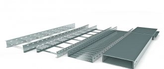
Main types
The use of this installation method reduces the number of personnel required for preventive maintenance and significantly improves the efficiency of the production process.
The main differences between the products lie in the material used to make the trays. The choice of raw materials depends on the installation in certain climatic conditions and the category of room.
Galvanized
This option offers the greatest resistance to corrosion. The use of galvanized steel maximizes its use in places with insufficient ventilation and high humidity.
Plastic
The main area of application is powering consumers by laying low-voltage cables. The installation location involves the installation of the following types of plastic cable trays:
- simple – provide high-quality protection from precipitation, damage and temperature changes;
- parapet - separate laying of wires that differ in purpose. The trays used at a height of 60-100 cm from the floor surface provide space for quick installation of sockets;
- skirting boards - perfectly perform the functions of discreet and neat laying along the floor in residential premises;
- cornice - simple transit of wires from one room to another under the ceiling.
Perforated and non-perforated
They differ from each other by the presence of special perforated holes.
In this way, excess heat generated when the cables are heated is removed, and the concentration of dust and moisture inside the duct is reduced.
The cost of such models is slightly higher than their analogues, but they have a wider range of applications.
Stairs
They are used mainly for industrial facilities with a widely ramified supply structure for equipment and machines.
This technology is becoming increasingly popular in the process of building new workshops.
The ladder option is used in substations as the most effective method of organizing cable routes.
Installation of plastic products
Special angles are used to connect multiple channels. Based on the design of the rotation of the product, they are divided into external and internal. Plastic plugs are widely used for decorative purposes. They are installed at the ends of the route.
Installation of metal trays
Laying metal channels requires special devices - connectors, brackets and plates, profiles and ends, covers and strips.
Ceiling pendant
1.The use of staples is necessary for secure fastening. These elements can be of two types - adjustable and unregulated.
For vertical fixation of trays to the ceiling, the second option is used.
The hole for fixing the tray to the bracket should ideally coincide with a similar hole for attaching the bracket itself to the ceiling.
If it is impossible to use this type, they resort to adjustable brackets. In this case, there is a discrepancy between the fixation lugs and the ceiling with the projection of the attachment of this element to the tray. As a result, we get the opportunity to rotate the structure and change the mounting location.
2.Suspended profiles and pipes are an intermediate component between the tray and the bracket. A profile is considered a more reliable type of connection.
Installation of additional elements on the tray is achieved using brackets.
Low- and high-voltage cables are separated from each other using separating profiles.
Rules for installing cable trays
There are a number of specific requirements when installing cable trays:
- Installation of such products is carried out in mandatory compliance with PUE standards. Installation is carried out at a height of 2 meters or more. In cases where there is an intersection with pipelines, the required distance must be maintained.
- To fix the structure, exclusively threaded connecting parts are used.
- The main line meets the main condition for normal operation - to be operated under voltage, with values not exceeding 1000 volts. To prevent the danger of cable overheating, the working volume of the wires in the tray is no more than half.
- Placing in bundles requires the presence of a maximum of 12 wires in one of them. 10 centimeters is the largest beam thickness.
- The connection is allowed after 1 meter for a vertical line, 4.5 meters for a horizontal line.
- A non-fixed position of the cable is allowed in sections of the horizontal straight configuration of the trays.
- Channels made of metal alloys and steel conduct electricity, so in this case grounding must be arranged. If this is not done, damage to the wiring insulation may result in electric shock.
- Screw connections serve as a reliable guarantee between sections, which allows them not to be grounded.
- Mandatory grounding is provided at the ends and in two places on opposite sides of the line.
Installation tutorial video
The main advantages of this type of installation:
- laying on the most difficult areas. An example would be premises with a significant amount of equipment;
- excellent parameters for saving cable structures. If when using shelves the distance between them is 0.75 meters, then the trays are two meters apart;
- the ability to remove and fasten cables at any required point as a result of perforation of the trays;
- The service life of the wiring increases due to the absence of kinks and sagging.
Source: https://jelektro.ru/covety-elektrika/%D0%BC%D0%BE%D0%BD%D1%82%D0%B0%D0%B6-%D0%BA%D0%B0%D0% B1%D0%B5%D0%BB%D1%8C%D0%BD%D1%8B%D1%85-%D0%BB%D0%BE%D1%82%D0%BA%D0%BE%D0%B2 .html
General test conditions
Cable support systems are tested for compliance with the declared characteristics and requirements of regulatory and technical documentation only after complete assembly in the standard position.
If the system uses non-metallic or composite components, testing the route of cable trays and ducts can be carried out no earlier than 168 hours after their manufacture.
General purpose cable support systems must be tested at a temperature of 20 +/- 5°C. If the system is sensitive to relative humidity, the manufacturer must provide appropriate information to adjust the test conditions.
Before testing, all protective measures must be taken, including the use of personal protective equipment for personnel participating in the test.
At least three sets of samples must be tested. The tests are considered successful if all three sets of cable trays or boxes passed them. If at least one of the sets does not pass the tests, then they are repeated on three new sets. Two sets must be supplied for testing: primary and repeat. If the second set is not supplied, or is supplied but has not been tested, the cable trays or ducts may be recognized as not meeting the requirements of the current State Standard. Tests must be carried out on coated specimens (if their design allows for this).
Protective coating for electrical trays
To protect electrical trays, manufacturers use 7 types of protective coating.
- Galvanizing (Z). Coating thickness 8-15 microns. Recommended for indoor use.
- Galvanizing using the Sendzimir method (ZS). Coating thickness 11-18 microns. Improved galvanizing using the conveyor method. Can be used for outdoor installation.
- Hot-dip galvanizing (G). Coating thickness 40-150 microns. Service life is 50 years. Works in aggressive environments.
- Powder paint (RAL). Coating thickness 1.5 mm.
- Stainless steel (S). Stainless steel trays are used in aggressive environments and in food production.
- Aluminum (Al). Where additional protection of cables from information removal is required, aluminum alloy trays are used, as well as on ships and navies.
- Zinc lamella (ZL). Thickness 4-20 microns. Coated with 70% zinc and 10% aluminum powder. This type of coating works in particularly aggressive environments, such as salt fog.
Rules for laying cables in channels
Cable laying in cable ducts is widely used. Cable ducts are made as standard from prefabricated reinforced concrete elements or from monolithic reinforced concrete (Fig. 5.7). In industrial premises, channels are covered with slabs at floor level.
If the territory is protected, then semi-underground channels with natural or artificial ventilation are used. But such channels should not interfere with transport communications and should not be combined with the general layout of the enterprise territory, since the level of overlap of such channels rises above the planning mark by 50...250 mm.
Cables in channels are laid on structures of various designs; laying along the bottom of the channel is also possible. The number of cables in a channel can be different and depends on the diameters of the cables and the brand of the typical channel; in channels of maximum size you can put up to 50... 60 power cables. If it is necessary to lay a large number of cables, it is possible to use double or triple-walled channels, but this makes it more difficult to make branches to individual consumers.
When laying cables in channels, they are provided with reliable protection from mechanical damage.
In table Figure 5.7 shows the main dimensions of unified cable channels (designations B, B, N in Fig. 5.7).
In areas where molten metal, high-temperature liquids, or substances that can damage cable sheaths may be spilled, the construction of cable ducts is not permitted.
Backfilling of power cables laid in channels is prohibited. The arrangement of cables on structures, depending on the standard sizes of the channels, can be:
- on one wall of the channel on suspensions;
- on one channel wall on shelves;
- on both walls on suspensions;
- on one wall of the channel there are hangers, on the other wall there are shelves;
- on both walls of the channel on shelves;
- at the bottom of the channel with a depth of no more than 0.9 m.
Electrical wiring is an integral part of electrical power and lighting networks of alternating and direct current with voltage up to 1 kV. Depending on the designs of the conductors, the characteristics of the premises and the environment, conductors are laid in various ways: openly on insulating supports or directly on building foundations and structures, in pipelines, on steel trays, in steel boxes, along stretched steel cables and strings, and also hidden in structural elements of buildings.
For open pipeless wiring, unprotected insulated wires and unarmored cables are used, therefore the routes of such wiring in their location must ensure the safety of the wiring from possible damage. Under normal production conditions, sufficient protection is considered to be the placement of wiring indoors at a height of at least 2.0...2.5 m from the finished floor or service area and at a height of at least 3.5...6.0 m from the ground level outside the premises. If necessary, open wiring is protected from touch and mechanical damage with special boxes or pipes.
Open wiring takes up a lot of space and increases the fire hazard, worsening the appearance of buildings and premises, but in general they are much more economical than hidden wiring. Hidden electrical wiring is carried out in the structural elements of buildings, in walls, floors, ceilings, and special channels. Office, office, and residential premises are now carried out only with hidden wiring.
Types of cables used
Before laying the line, the type of low-current cable is selected - its functional purpose is taken into account. The brand is indicated in the wiring diagram. In the case of digital data transmission and broadcasting television signals, coaxial cable is used. Twisted pairs are used to transmit digital/analog signals, and stranded, shielded wires are used for discrete ones.
The laying of low-current cables in rooms is most often carried out in a hidden way - the boxes not only provide protection, but also improve aesthetics. If there is no risk of damage, the wires can be stretched along the walls without using a protective box (open method). Outdoor installation is carried out underground (the most protected, but quite labor-intensive method) or over the air (wires do not require trenching, but they are poorly protected from weather factors).
Some gasket features
- Wires or electrical cables can be laid in rows individually, in bundles, in bags or in multilayers. When laying wires in rows in one layer, the recommended clearance between adjacent wires is five millimeters. When laying in bunches or packages, the gap increases to 20 mm; when laying in multi-layers, no gap is allowed at all.
- When laying wires in bundles, it is necessary to ensure that there are no more than twelve wires in one bundle, and the diameter of one bundle should not exceed 10 cm.
- When laying wires horizontally on cable trays, it is recommended to tie them into bundles with a pitch of at least 4.5 meters. At the same time, in straight horizontal sections it is allowed not to tie the wires into bundles at all. When laying wires vertically in mounting boxes, the minimum linking step is 1 meter.
- After the metal structure of the cable-supporting route has been assembled and secured to the floors of the building with a special cord, the length of the route is measured for measuring cutting of electrical cables and wires. After cutting, the wires are grouped into bundles, bandaged and equipped with marking tags. After laying the electrical wires in trays and boxes and connecting them into a single circuit, the “phase-zero” continuity is checked and the insulation resistance is monitored with an ohmmeter.
- Laying of wires in cable trays and ducts must be carried out at a certain temperature. At ambient temperatures from -15°C and above, it is permissible to lay cables without preheating them. In the temperature range -40...-15°C, cables and wires must be preheated before laying. At air temperatures of -40°C and below, cable laying is prohibited.
- Electrical cables and wires are laid in electrical boxes with a reserve length necessary to compensate for temperature deformations and possible soil displacements. The electrical cable supply must be laid straight. Laying the stock in rings or coils is not allowed.
- When laying cables and wires openly in plastic or metal cable ducts, their possible heating under the influence of solar radiation should be taken into account. In this case, sun screens are additionally provided.
- Any cable line must be as complete as possible (laid in entire construction lengths), that is, have a minimum number of couplings.
- Electrical cables, regardless of the design of the supports, must be fastened at the end points, at connecting or end couplings and at turns of the highway. It is recommended to fasten straight sections of the cable route in increments of 1.0-1.5 meters. When laying wires in bundles, the fastening pitch can be increased to 8-10 meters.
- Installation of an electrical cable must prevent possible deformations from: • the cable's own weight; • mechanical stresses that arise from cyclic heating and cooling; • magnetic interactions that occur during short circuits.
- When crossing a cable route with a pipeline, the distance between the cable trays and the pipeline must be at least 5 cm. If they are located parallel, the minimum distance increases to 10 cm. If gas or flammable liquid is transported through the pipeline, the shortest distance to the cable tray is taken to be 25 cm .
- When laying electrical wires in a cable tray, for ease of maintenance in future operation, as well as for natural cooling purposes, it is recommended to fill no more than 50% of the volume of the electrical box.
- When organizing a cable route using cable trays and ducts, you should ensure that during installation the individual elements have reliable metal contact with each other, since usually only the beginning and end of the cable support system (or one branch) are grounded.
- Cable trays and ducts are mounted at a height of at least two meters from the floor or service area. In rooms where only specially trained personnel can work (for example, in electrical rooms), installation of metal trays at any height is allowed.
- The method of installation of electrical boxes and trays must exclude the possibility of moisture accumulation in them. For open laying of cables and wires, boxes with a removable lid are usually used to ensure easy access. For hidden wiring, the use of pipes and “blind” boxes for wires is allowed.
Options for supplying power cables from power lines
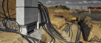
In the process of installing electrical wiring at the dacha, the owner will certainly be faced with the question of how to connect the power supply to the household. The cable line will need to be pulled from the nearest overhead power line support, naturally after obtaining the necessary permits, together with representatives of electrical network services. You can use one of the following options for connecting to a power line support:
- by air;
- underground.
Supplying a cable to a country house by air
Next, we will consider in detail the advantages, disadvantages, as well as important installation nuances for each of the options.
Air supply
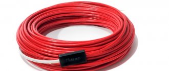
Supplying power to a country house by air can be done using two methods. The first involves the use of SIP cable, which means self-supporting insulated wire. It stretches directly from the power line to the facade of the house. The second option is accompanied by pre-tensioning of the metal cable from the support of the centralized electrical network to the walls of the house using special hooks or talpers. This allows you to use any cable cables that are subsequently fixed to the cable.
Regardless of the chosen method, you will need to use additional insulating fasteners to secure the conductive wires. The following factors will need to be taken into account:
- If the distance from the power line support to the construction site is more than 25 meters, intermediate support pillars should be installed.
- In winter, the load on the wires will increase due to the accumulation of ice. In this regard, it is necessary to correctly calculate the load-bearing capacity of the cable.
- Ultraviolet radiation contributes to the mechanical destruction of the insulating layer of conductor cores. Therefore, it is necessary to use additional protection in the form of corrugation.
Standards for connecting a house to a power line
Connecting electricity to a country house from a pole via air is carried out in the shortest possible time. You will need to purchase special fasteners and also use a tower. This comes with additional costs.
Power supply underground
When powering a country home with a cable laid underground, it is recommended to adhere to the following rules:
- The wires are laid in a trench at least seventy centimeters deep. Except for the case when the cable line is laid in a protective pipe, and the length from the power line support to the input panel is less than five meters. Under such conditions, it is possible to prepare a trench 50 cm deep.
- The trench must be dug at a distance of at least 60 cm from the foundation. If there is a need to lay a cable through the foundation, then you will need to use an additional pipe in it. It is prohibited to pull conductive conductors directly under the foundation.
- When excavating a trench, the following distances should be maintained from various objects:
- 75 cm - bush plantings;
- 100 cm - sewerage, water supply;
- 200 cm - trees, gas pipeline.
- The cable must be armored and have appropriate insulation protection.
Electricity supply to the house underground
The listed instructions are determined by the requirements of PUE, PTE and SNiP, regardless of the selected cross-section of current-carrying conductors.
The main advantage of this option for connecting a country house to a centralized power supply is the minimal cost of the required material. You can also do without using special equipment. Laying the power cable underground will be difficult if the area is tiled or concrete is poured.
conclusions
This review of the types of electrical trays is based on the well-known large Russian manufacturer of cable routes, the OSTEC company.
©Elesant.ru
More articles
- The importance of calculating cable cross-section
- Recessed ceiling LED lights
- Cable channels of open wiring in residential and office premises
- NUM cable, description, application
- Flexible power cable KG: description, characteristics, purpose
- What cable trays are used in electrical installations?
- Terminal blocks for DIN rail: classification, photo
- Distribution box: description, types and types of distribution (junction) boxes
- Mounting boxes for electrical installation: classification and types
- Electrical trays: description, use, regulatory documents