Electrician in the house
Encyclopedia about electricity from A to Z
Masters catalog
Find the best master or company in your city
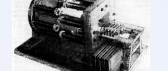
Working tachogenerator
Undoubtedly, the development of mankind in recent centuries is inextricably linked with the development of energy sources and their effective use. Moreover, we can say that the level of development of a country directly depends on the amount of energy produced.
The first source of energy to bring about the Industrial Revolution was steam, but its hegemony was soon replaced by the power of electric machines. Today we will talk about DC tachogenerators - devices that have made a huge contribution to the progress of mankind.
- Some historical information
- Micromachines in electrical engineering The principle of operation of tachogenerators and their structure
- Tachogenerators Long Life
- Errors of asynchronous tachogenerators
Some historical information
The 19th century became a turning point in history for humanity. It is significant for the greatest scientific discoveries, including in electrical engineering.
Michael Faraday - discoverer of the law of electromagnetic induction
- At that distant time, the famous English experimental physicist Michael Faraday discovered the law of electromagnetic induction. This event can be considered the starting point for the electrification of the planet. Further development and practical application of this knowledge was only a matter of time.
Boris Semenovich Jacobi - the contribution of Russian scientists to the development of electricity is perhaps the most significant
- In 1834, Russian physicist B.S. Jacobi presented to the world the design of the first electric machine, which, as it later turned out, became the prototype of all modern electric motors.
Pavel Nikolaevich Yablochkov
- The next significant step was the appearance of transformers and their practical use. In 1876, this discovery was made by the Russian scientist P.N. Yablochkov. He also invented electric candles and proved the practical benefits and safety of using alternating current.
Interesting to know! Before Yablochkov’s research, the entire scientific world community believed that using alternating current was impossible and dangerous.
Mikhail Osipovich Dolivo-Dobrovolsky
- In 1889, Russian engineer M.O. Dolivo-Dobrovolsky invents a three-phase asynchronous motor, thanks to which electric machines began to be used most widely in industry. The design of this device was extremely simple and at the same time reliable.
- As a result, by the beginning of the 20th century, all the main types of electric machines had already been created, which are actively used to this day. They are used in various industries and devices.
Micromachines in electrical engineering
In addition to powerful units, low-power machines, also called micromachines, were also required. They are actively used in computer and automation devices as functional elements.
- These types of devices are usually divided into three groups: electrical machine amplifiers, actuators and information machines.
- The former serve to amplify the power of electrical signals.
- Actuator motors are responsible for converting electrical current into mechanical force. These devices can be asynchronous, stepper and direct current.
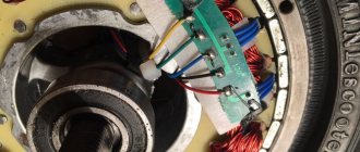
In the photo - tachogenerator
- Information machines consist of tachogenerators, selsyns, magnesins and rotating transformers. The purpose of these devices is to convert non-electrical quantities into electrical signals. In particular, a direct current tachogenerator measures the rotation speed of a certain object and is used in various electric drive devices, machine tools, vehicles, etc.
The principle of operation of tachogenerators and their structure
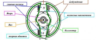
Schematic structure of a DC tachogenerator
A tachogenerator is a device equipped with a shaft, which, when it rotates, produces an output electrical voltage, the value of which is directly proportional to the speed at which the shaft rotates. This feature means that the tachogenerator DC motor is essentially equipped with a permanent magnet or independently externally excited encoder.
A gasoline DC generator operates on the same principle as a tachogenerator.
- The design of the tachogenerator is practically indistinguishable from the design of other DC machines. They are used to measure rotational speed based on the output voltage value and to obtain an electrical signal with the shaft rotational speed in auto control circuits.
The diagram shows a classic sliding contact
- Voltage pickup occurs through a sliding contact, which traditionally consists of a copper commutator and graphite brushes.
- This design has the peculiarity that, due to the fact that an oxide film is formed on the copper, the contact resistance may change with some periodicity. For this reason, fluctuations in the voltage produced by the tachogenerator occur, which are perceived as noise.
Interesting to know! At low speeds, the tachogenerator noise is compared with the useful signal.
- Despite this drawback, this design remains the most popular, since graphite has excellent sliding properties, which means the device lasts much longer than its analogues.
- If a tachogenerator is required that does not have this drawback, then a silver contact track is applied to the collector. This metal does not oxidize, which means that the resistance readings always remain at the same level.
Tachogenerators Long Life
Tachogenerator Long Life
Tachogenerators assembled according to “Long life” stand apart. These devices are designed to work in areas where long-term uninterrupted operation is required. They are incredibly wear-resistant, so they last a very long time.
- The technical characteristics of AC tachogenerators of this type are impressive. Operating temperature range from -50 to +100 degrees Celsius. Possibility of measuring rotation speed with an accuracy of 1:100000 in real time.
- The cylinder of these devices can be hollow or solid.
- The shaft mounting is flange or claw.
Magnetoelectric machines
In connection with the development of alni (Al – Ni), alnico (Al – Ni – Co) alloys, as well as a number of other alloys with high magnetic properties, it has become possible to manufacture machines without an excitation winding, with permanent magnets on the inductor. In particular, actuator motors with armature control with a power of up to 50 - 100 W are manufactured with permanent magnets.
With permanent magnets it is also possible to build generators and general-purpose motors with a power of up to 5 - 10 kW and higher. Such machines have become widespread.
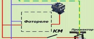
Constant automation schemes
So, we have already said that tachogenerators are used in automatic circuits, now let's take a closer look at how they are involved there.
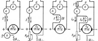
Direct current tachogenerator connection diagram
- Above is a schematic diagram of connecting a tachogenerator.
- The OB winding is connected to a DC source. In this case, the tachogenerator, coming into a state of excitation, and if its armature is set in motion with a certain frequency, it will begin to produce a constant voltage at the output.
- Moreover, the higher the device resistance Rh, the steeper the Cu characteristic at the output. The value of the greatest steepness will correspond to the idle mode of operation of the tachogenerator - this happens when the winding at the armature opens.
- Accordingly, with increasing load, the opposite phenomenon is observed.
- The tachogenerator outputs a current characteristic in the form of a constant line, but this corresponds to reality only at low rotation speeds. If you increase them, the characteristic will become curvilinear. If the load resistance RH decreases, the curvature effect will also increase.
- This is explained by the fact that the armature has a demagnetizing effect.
Advice! To prevent the generator from producing a curved output characteristic, you do not need to run it at the highest possible speed, and use only devices with low internal resistance as a load.
Structure of a synchronous tachogenerator
- It is also worth considering the point that in real conditions there is a voltage drop in the brushes, which is why the output characteristic does not come from the origin of coordinates, but with some displacement. This phenomenon is the reason for the appearance of a dead zone in tachogenerators, in which no voltage is created.
- To reduce the dead zone, brushes with low resistance are used, usually copper-graphite or silver-graphite. High-precision models use brushes with silver or gold tips. However, these devices still have some error, within 0.2-0.5%.
Summary
Whatever the type of tachogenerator, each of them has its own pros and cons. Therefore, when choosing equipment, we proceed from certain conditions of its functioning, as well as the requirements of the automatic device intended for it.
What is a tachogenerator used for? We found out that the units have found application in automatic devices, as well as in control systems in the form of an inertia-free element. For systems where the output value is the angle of rotation, such equipment acts as an absolute differentiator. In the electrical circuit to which it is connected, inertia is accepted as an additional aperiodic link.
Asynchronous tachogenerator
Schematic structure of an asynchronous tachogenerator
The design of an asynchronous tachogenerator is exactly the same as that of an asynchronous electric motor with a non-magnetic rotor (hollow).
- The stator field winding is connected to an alternating current source, and the output voltage is removed from the generator winding (GO).
- Its principle of operation is as follows: the excitation winding is powered by an alternating current of a certain frequency, resulting in a pulsating magnetic flux that constantly changes direction.
What is an asynchronous tachogenerator
- Due to the influence of this magnetic field, two types of EMF are induced in the rotating rotor - rotational and transformer.
- On the circuits that are perpendicular to the axis of the excitation winding, currents caused by the rotational emf also begin to flow. These currents also, pulsating, induce a new EMF - output.
- Without delving into physical calculations, we can say that an asynchronous tachogenerator is an asymmetrical two-phase unit that can be studied by symmetrical components.
Errors of asynchronous tachogenerators
The output voltage produced by this type of tachogenerator is a complex value, which indicates phase and amplitude errors.
Calculation of errors of an asynchronous tachogenerator
- Phase error is the deviation in degrees of the output voltage phase from the base voltage phase, that is, the excitation voltage. This effect occurs mainly due to the inductive reactance of the stator and in most of the rotor. This type of error can be reduced by correctly selecting the characteristics of the applied load.
- Amplitude error is the deviation of voltage readings from rotational speed from the ideal value in which they should be equal. This indicator is expressed as a percentage.
Tachogenerator drawing
Just as in the case of phase error, this effect can be reduced by properly configuring and calibrating the asynchronous tachogenerator.
- The physical reasons for the amplitude error are as follows. Firstly, there is a voltage drop in the generator winding. Secondly, the excitation current changes, followed by the magnetic flux, since the transformer EMF of the rotor causes demagnetization. The third reason is that the magnetic flux of the generator winding opposes the magnetic flux of rotation, which is why it decreases somewhat.
- It is also worth remembering that the rotor has some inductive reactance, which also affects the magnetic flux of rotation, reducing it.
- And lastly, the rotational magnetic flux induces a rotational emf, which means a new current and magnetic field appear, which also opposes the excitation flux. This electromotive force is proportional to the angular speed of rotation, which means that as the rotor speed increases, it will also increase and the resistance will increase. This is expressed in a voltage drop in the excitation winding and a decrease in the magnetic flux of rotation.
- It is interesting that it is impossible to simultaneously reduce both the phase and amplitude errors. Therefore, the connection diagram is debugged in such a way as to reduce the most influential errors in a particular case.
Interesting to know! In practice, it has been proven that at low rotation speeds of an asynchronous type tachogenerator, both types of errors are quite small, which is why the rotation ranges of devices are limited to specific values.
Although these types of errors are the main ones, they are far from the only ones:
- The zero signal is the voltage present on the generator winding when the rotor is stationary. This parameter does not remain constant, as it changes when the rotor turns. It consists of two components: constant and variable.
- The constant variable occurs due to imprecise shifting of the windings; the presence of short-circuited circuits in the windings and core; unequal magnetic permeability; uneven air gap; scattering fluxes and other things.
- The variable component is due to the uneven thickness of the rotor walls if it is hollow, which causes a difference in the active resistance of the circuits, and therefore a difference in current and magnetic flux.
- To weaken the constant component of the zero signal, the windings are installed on different stators: one is placed on the internal one, the other on the external one. In this case, during the assembly of the asynchronous tachogenerator, the internal stator rotates until the zero signal reaches a minimum value.
- The variable component can only be overcome by calibrating the rotor and its symmetry.
Tachogenerator output characteristics
- The next error is called output voltage asymmetry. It is expressed by the inequality of voltages produced by the tachogenerator when rotating in different directions. The effect is especially noticeable at low speeds.
- The reason for the phenomenon is related to the residual EMF from the zero signal, because its phase remains constant, while the rotation phase shifts by 180 degrees. They combat the problem by reducing the zero signal.
- The last type of error is temperature. The influence of the ambient temperature, as well as heating during operation of the rotor, affects the active resistance of the windings on the stator and rotor. All this, in turn, affects the ideal output voltage and increases the amplitude and phase errors.
- To stabilize the change in the resistance of the field winding, thermistors are connected in series. The rotor is made of materials with the lowest possible temperature coefficient.
Advantages and disadvantages [edit | edit code ]
- The tachogenerator-tachometer pair does not require additional power sources; it is simple and quite reliable in operation.
- Tachogenerators cannot measure very slow rotation - the amplitude of the generated signal becomes very small.
- Tachogenerators create additional frictional torque on the rotating shaft, which introduces some error into the measurements, but usually it is insignificant.
- They contain rubbing parts and therefore require periodic maintenance.