We connect single-core and stranded wires
How to connect a single-core and stranded wire so that this does not lead to problems in the future, and the contact connection serves us for many years? And in general, how to properly connect different types of wires?
We will try to answer all these questions in our article, and we will also analyze what such rules are associated with and what dangers are hidden behind an incorrect connection.
Why contact connections must be made correctly
First of all, let's look at what the requirements for high-quality contact connections are related to.
It is not without reason that clause 2.1.21 of the PUE separately stipulates methods for connecting wires, and allows only screw or bolt clamps, crimping, welding or soldering. Poor contact is the main cause of fires
This is primarily due to the fact that these types of connections can provide the proper level of durability and reliability of the connection
After all, any electrician will tell you that more than 90% of all damage occurs at contact connections, and that is why so much attention is paid to them.
After all, what is a poor-quality contact connection is a connection that has a high contact resistance. And since we have resistance, this means heating.
Dependence of resistance on conductor temperature
- As we remember from the physics course, any conductor in a heated state has greater resistance than a conductor with a lower temperature. Therefore, an avalanche-like process results. A poor-quality contact connection causes the conductor to heat up and its resistance increases even more. As a result, it heats up even more until it reaches the point where it simply melts.
- As a result, our main task is to ensure minimum resistance between the two conductors being connected. This is achieved by ensuring the proper area of contact between the two conductors, as well as by ensuring the maximum possible contact between them.
- Let's immediately look at why we will not consider the question of how to twist single-core wires or their multi-core counterparts. Indeed, with the right approach, and through twisting, it is possible to ensure a sufficient area of contact and compression of the conductors with each other.
Twisting is prohibited
The fact is that in any case, the contact connection will be subject to temperature influences. That is, it will heat up and cool down. And as we know, heating leads to expansion of materials, and cooling, accordingly, to contraction. As a result, our contact connection, which is not fixed by any third element, can quickly become of insufficient quality.
Prelude to a conversation about wires
Let's compare single-core and multi-core cables. Which one can conduct sound better to the speaker system? Which one will be the best speaker to play on? Strange questions, but they are asked. Some say that multi-core transmits the signal from the amplifier to the acoustics better, others argue with them.
All of us, one way or another, studied physics at school. Therefore, we still have a general idea of what cross-section, thickness, current and voltage are, as well as resistance. Therefore, let’s take two two-wire cables, three meters long, and continue our reasoning.
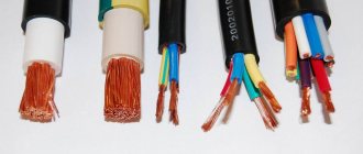
Solid wire
One will be single-core, as in the picture below - VVG 2*2.5. This type of wire is used by electricians when laying electrical wiring (in a house, apartment) in a groove where wiring of a grounding conductor is not required. That is, they lay it in such a way that it will no longer be exposed to external influences.
In other words: it will not bend and bend many times. Just as they laid it, it will be walled up in the wall. This is the right decision, since it is possible to lay stranded wire in grooves, but this will be very inappropriate due to the cost of stranded wire.
Stranded wire
The second wire will be multi-core - PVA 2*2.5, as in the picture below. It is usually used in extension cords and when connecting any devices and appliances to the electrical network.
So, we took two different wires VVG 2*2.5, three meters long, and PVS 2*2.5, the same length. Their cross-section, according to the passport, is 2.5 square (mm2).
How to measure the cross-section of a stranded wire? There are no difficulties - you just need to find out the thickness of one “hair” from this wire, and then count the number of these same wires. Next, multiply the number of wires by the diameter of one “hair”. We will take measurements with a micrometer and use the formula.
What is the best way to reliably connect two cables together?
Methods of connecting cables that require equipment and skills in the field of electrical engineering:
Simple connection methods that do not require tools or knowledge:
- connection using terminal blocks;
- spring clamps;
- PPE caps;
- bolted connection.
The choice of connection method depends on the characteristics of the wires. It is necessary to take into account the type and material of the core, the number of wires, and operating conditions.
With soldering
Soldering is a common method of connecting cables. To work you need a soldering iron, rosin, solder and sandpaper. How to connect wires by soldering:
- stripping of insulation;
- cleaning from oxides using sandpaper;
- the conductors need to be tinned - rosin is placed on the wire, it is heated with a soldering iron until the wire is covered with rosin;
- the conductors are assembled together, bubbling rosin must be applied to them and heated until the solder spreads;
- The soldering area is cooled.
The complexity of the process lies in the availability of professional skills. Do not overheat the solder area or twist it when heating, otherwise the insulation may melt
It is important to ensure high-quality and reliable contact of the wires. Soldering is used in low-current electrics
No soldering
Wires are connected without soldering using special connecting elements. It is also possible to connect the wires by twisting. Twisting is the simplest method that does not require equipment, but this method is also the most unreliable.
Copper
Copper wire can be connected using terminal blocks, Wago clamps (necessarily using special paste), using a bolt, or soldering.
Aluminum
Aluminum wires can also be connected using any method, but with some special features. When connecting, the metal must be manually stripped of insulation.
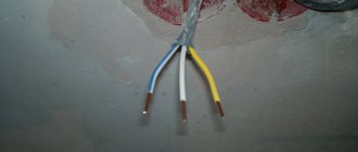
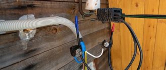
Preparing a Stranded Conductor
When stripping the end of a stranded copper conductor, it turns out that the thin wire cable begins to change shape. Before this, the twist was held in place by a layer of insulation, but now the hold is gone, residual elasticity causes the wires to straighten, and the rod fluffs up into individual elements. Each unconnected wire:
- Reduces the overall nominal cross-section of the joint, the permissible current density through the contact drops, the temperature rises;
- If left outside the insulation, it may cause electrical injury and short circuit.
Pre-treatment of the stripped ends of the stranded wire is required to prevent fraying and obtain a homogeneous, monolithic section.
Service
Until recently, one of the more accessible, popular methods of preparation was tinning. For this:
- The insulation is stripped to the required length, the wires are carefully twisted tightly together;
- Using a heated soldering iron, melted rosin is transferred to the surface of the core. The metal warms up, the rosin impregnates the wire rope;
- The tip of the soldering iron tip picks up solder and transfers it to the tinning site. The solder spreads over the surface of the hot wires, filling all the gaps, forming a molecular bond with the metal;
- After cooling, the remaining rosin is removed with gasoline or alcohol, and the surface is treated with sandpaper to remove possible “strings” of solder in the form of thin long needles.
Has the meaning:
- Rosin is a flux that is used during soldering to remove oxides from the metal surface, improves heat transfer and heat distribution at the soldering site. For tinning the conductors, it is prohibited to use fluxes containing acid or other active components for removing oxide, which will lead to destruction of the conductor;
- Lead-tin solder is used. The retail chain offers a huge number of solder pastes, consisting of a mixture of solder and flux. They are very comfortable. It is allowed to use only those that have a mark on the trade label indicating that the flux is not active.
But, if the soldering iron is still hot, the easiest way is to tin the same hard conductor and connect them by soldering. The result is a strong, reliable joint with minimal contact resistance.
The method requires a soldering iron, consumables, the presence of electricity at the installation site, work skills, careful careful execution, and takes a lot of time.
Crimping
This method of preparing the stripped end of a flexible core requires the presence of press jaws and consumables - sleeves, the internal diameter of which corresponds to the diameter of the core. The process takes incomparably less time and labor than tinning:
- The stripped end of the strand is twisted tightly and placed in a sleeve;
- Press pliers compress the outer surface of the sleeve, tightly clamping the wire with the body. The resulting dents hold the cores more securely.
The finished pressed end is used in any type of joint. If you need to connect it to a single-core one, it makes sense to immediately take a sleeve, the diameter of which will allow you to place two conductors inside it. Simultaneous crimping will give a good joint. In this case, preliminary tinning of the stranded wire is not required.
What is a junction box
From the electrical panel, the wires disperse throughout the rooms in the house or apartment. Each room, as a rule, has more than one connection point: there are several sockets and a switch. To standardize the methods of connecting wires and collect them in one place, distribution boxes are used (they are also sometimes called branch boxes or junction boxes). They contain cables from all connected devices, the connection of which occurs inside the hollow housing.
In order not to look for wiring during the next repair, it is laid according to certain rules that are prescribed in the PUE - Rules for the Construction of Electrical Installations.
Electrical wiring rules
One recommendation is to carry out all connections and branch wires in the junction box. Therefore, the wires are run along the top of the wall, at a distance of 15 cm from the ceiling level. Having reached the branch point, the cable is lowered vertically down. A distribution box is installed at the branch point. It is where all the wires are connected according to the required circuit.
According to the type of installation, junction boxes are either internal (for hidden installation) or external. Under the internal ones, a hole is made in the wall into which the box is built. With this installation, the cover is flush with the finishing material. Sometimes during the renovation process it is covered with finishing materials. However, such installation is not always possible: the thickness of the walls or finishing does not allow it. Then a box for external mounting is used, which is attached directly to the wall surface.
Some forms of junction boxes
The shape of the junction box can be round or rectangular. There are usually four conclusions, but there may be more. The terminals have threads or fittings to which it is convenient to attach a corrugated hose. After all, it is more convenient to lay wires in a corrugated hose or plastic pipe. In this case, replacing the damaged cable will be very simple. First, disconnect it in the distribution box, then from the consumer (socket or switch), pull it and pull it out. Tighten a new one in its place. If you lay it the old fashioned way - in a groove, which is then covered with plaster - you will have to drill into the wall to replace the cable. So this is the recommendation of the PUE, which is definitely worth listening to.
What do distribution boxes generally provide:
- Increased maintainability of the power supply system. Since all connections are accessible, it is easy to determine the area of damage. If the conductors are laid in cable channels (corrugated hoses or pipes), replacing the damaged section will be easy.
- Most electrical problems arise in the connections, and with this installation option they can be inspected periodically.
- Installing distribution boxes increases the level of fire safety: all potentially dangerous places are located in certain places.
- Requires less money and labor than laying cables to each outlet.
Connecting a switch with two keys
Connecting a switch with two keys in a distribution box is more complex than with a single-key switch.
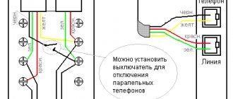
The scheme is characterized by the fact that a cable with three cores must be laid to the device for 2 groups of lamps (if there is no grounding). One conductor is connected to the common contact, and the other two are connected to the output to the keys. You need to remember which conductor (by color) was connected to the common contact. The phase that comes in is connected to the common wire of the switch. The neutral wires from the input, as well as from the two light bulbs, are twisted - three conductors together. There remains a phase wire from the lamps and two from the switch. They are connected in pairs - one conductor from the switch to the phase of one light bulb, and the second output to the remaining lamp.
Twisting wires
The simplest way to connect two or more conductors is the so-called twisting. This connection is made using various techniques, of which simple twisting is intuitive.
The connection of two flexible stranded wires in the form of a simple parallel twist provides reliable contact between the two wires, but the twist does not tolerate vibration and the force applied to breaking.
Using parallel twisting, you can connect solid and stranded copper wires; thanks to the additional bending of the solid wire, this connection is more reliable than when connecting two stranded wires.
A similar method is used to connect aluminum wires of different sections.
The use of parallel twisting makes it possible to provide electrical contact simultaneously between two or more wires.
A simple twist can be used to electrically connect an additional wire to the main wiring line without breaking it.
The same joining method can be used to join together a solid wire drop to a flexible or solid main wire.
To connect two wires together, they can be sequentially twisted, for which each connected wire is “wound” around the other.
This method of connecting wires allows for optimal contact and reliability of the connection, but only for two wires.
The connection of rigid wires to each other can be done using bandage twisting. To do this, the wires to be connected are applied parallel to each other, after which they are fixed in this position using a softer wire, which is laid tightly on the bare surface of the wires.
The tighter the twisting or winding is done, the better the electrical contact between the conductors will be.
Using a bandage, you can connect two or more conductors or organize bends.
To improve fixation, you can additionally bend the monolithic wire, thereby fixing the bandage.
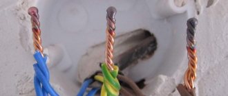
During installation, it is necessary to ensure that the twisted parts of the conductors are completely cleared of insulation; the copper or aluminum surface of the conductors must be clean and free of traces of oxidation. If necessary, before twisting, the surface of the connected wires must be cleaned with a knife or sandpaper. To increase twisting density, and, as a result, electrical contact between conductors, twisting can be done using pliers
It is important to remember the main installation rule - you cannot directly connect copper and aluminum wiring
Why twisting is not the best option
The reliability and quality of the connection between two wires depends on the contact area between them. Aluminum, from which wires for electrical wiring were made in Soviet times, is a fairly ductile metal and when the ends of aluminum current-carrying wires are twisted, they are deformed.
This makes the contact area larger, which reduces the heating of the connection and increases the service life of the twist.
Copper is more rigid and more effort must be applied to deform it, so twisted copper wires have a smaller contact area.
As a result, the connection begins to heat up when electric current flows, and cools down in its absence. Such heating-cooling cycles are accompanied by thermal expansion and contraction, which weakens the twisting, in which the wires, apart from their own elasticity, are not pressed against each other by anything. The weakened twist heats up even more, which accelerates the process of destruction until complete failure.
Therefore, twisting can only be used as an intermediate step before soldering or welding. In other cases, other splicing methods must be used to connect the wires.
A quick connection with big consequences
We often don’t think about the consequences of such a “simplification”. Meanwhile, an unreliable contact will fail at the most inopportune moment; the power supply to consumers/power receivers can always be cut off. Voltage “surges” cause breakdown of the elements of the power cascades of complex SBT household appliances. Even special protection devices used in the most “sophisticated” models of foreign manufacturers cannot save you from breakdown.
The induction of short electromagnetic pulses with a voltage of several thousand volts onto the electronic filling causes “harmless” sparking at the joints. At the same time, the standard protection equipment with which apartments are now equipped (RCDs, circuit breakers, fuses) do not “see” such short low-current pulses, so they simply do not trigger them, and we do not accept installing special devices for this. Uninterruptible power supplies for computers also did not become a panacea for transient impulses. The occurrence of “poke” causes malfunctions in the operation of electronic equipment and computer equipment, leading to failure of electrical components and expensive functional modules. Overheating at the site of a poor connection leads to even more catastrophic consequences; when current passes, the weakened connecting node becomes red-hot. This often causes fires and fires, causing enormous damage to the owners of the premises. Statistics show that 90% of all electrical wiring faults occur due to twists and poor contact connections of conductors. In turn, the very malfunction of electrical wiring and equipment, according to the Ministry of Emergency Situations, is the cause of one third of the fires that occur in Russia.
However, it so happened historically that several decades ago, in conditions of a shortage of electrical accessories/copper conductors, twisting aluminum wires was considered the main method used in electrical installation work. Twisting as a connection can be used in electrical engineering when carrying out repair and restoration work.
The need for a reliable connection
First of all, you need to understand why it is so important to pay attention to the reliability of the conductor connections. Even the PUE give recommendations on the choice of connection method and strictly prohibit twisting of wires
Consequences of incorrectly connected conductors:
- Fire. A poor-quality contact has a high contact resistance. This leads to heating, which can later lead to a fire.
- Damage to wiring. Due to high resistance, the conductor heats up faster. As a result, the insulation may melt and the contact itself may collapse. Damage to the insulating layer may result in electric shock.
- Short circuit. It also depends on the value of the contact resistance.
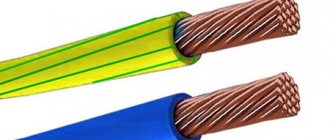
Difference between cable and wire
Difference between cable and wire
A cable is a plastic or rubber line that places several insulated conductors inside. The conductors are combined into a single system for ease of installation and operation, and protection from external influences. A special cable can be easily distinguished by the presence of an armored casing that prevents damage due to mechanical action.
A wire is a stranded or single-core carrier, equipped with light tubular insulation or represented by a hollow metal rod with a core cross-section of 1.5 mm.
The differences between cables and wires are in the number of cores, type of insulation, marking and purpose. Due to the double insulation of the current-carrying conductors, the cable passes large currents and voltages relative to the wire. The difference is hundreds of kilovolts in favor of the cable.
Outer shell
According to GOST 15845-80, a wire is one conductor, a cable is two or more insulated cores combined in additional insulation. If there is no protective sheath on two or more metal rods, it is classified as a wire.
Explanation of meanings
Cable and wire markings differ in letters and numbers.
Wire names contain the following meanings:
- the letter "A" in front indicates that it is aluminum wire;
- “P” – copper wire;
- “PP” – 2 or 3 flat copper conductors;
- the following values: “P” – polyethylene insulation, “P” – rubber, “B” – vinyl, “L” – cotton braid;
- “N” – additional protection with non-flammable nairite, “B” – vinyl;
- “G” – the letter makes the difference in marking, thanks to the flexible current-carrying core;
- “TO” – anti-rot coating.
Power cable marking
When marking cables, GOST establishes the following procedure:
- Core type. “A” – aluminum, absence of letter – copper.
- Purpose. “K” – control, “KG” – with increased flexibility.
- Protection. “P” – polyethylene, “V” – vinyl, “R” – rubber, “NG” – non-flammable and “F” – fluorolone shell.
- Armor or external covering. “A” – aluminum, “C” – lead, “P” – polymer, “B” – vinyl, “P” – rubber, “O” – coating of all phases, “Pv” – vulcanized plastic.
- Protection. “B” – anti-corrosion armor, “Bn” – non-flammable armor, “2g” – double PVC tape, “Shv” – vinyl hose, “Shp” – polymer hose, “Shps” – self-extinguishing polymer hose.
Scope of use
Category 5 cable
Reliable protection against mechanical and aggressive action, extended service life, rated voltage are the main features of the cable, which should be distinguished from wire when installed in special conditions. Powerful insulated systems are suitable for laying electrical networks under water, underground, in mines, in areas of high fire hazard and corrosion activity.
According to the PUE (electrical installation rules), the cable is divided into 5 categories:
- Power ones are designed for transmitting electricity; they are installed stationary or when connecting mobile consumers.
- Installation conductors are used when laying devices between devices. They cope well with elevated temperatures and voltages of 500 V.
- Communication devices are found in alarm and wired communication systems.
- Control lines are well proven for connecting control and lighting circuits in 600 V electrical equipment.
- RF and optical media transmit energy and signals at specified radio frequencies or optical wavelengths.
Wire PUGNP
According to the area of application, wires are classified into installation, power, and installation groups. The former are used for flexible or fixed wiring in distribution boards, radio and electronic equipment manufacturing. Power options are part of electrical networks; installation wires are applicable when connecting installations and power transmission systems inside and outside buildings.
- For stationary installation in enclosed spaces, suitable wires are PUGNP, PUNP, APUNP, PVS.
- Installation and mounting products - PV-1, PV-3, APV, MKESH - are laid in pipes, construction voids, cable trays and under plaster.
- In places that require increased heat resistance, PNSV wires are used.
- For overhead lines, SIP-2, SIP-3, SIP-4 are suitable
- Low-current communications – PRPPM, TPPep, TRP.
Life time
The average service life of a cable is 30 years, wires - from 6 to 15 years. The duration of operation is determined by the presence/absence of two or more insulations and an armored shell.
Construction portal No. 1
It is a fact that the current strength and conductivity are better, but is there a scientific explanation and the magnitude of the difference in current conductivity in single-core and multi-core copper wires.
Why will conductivity be better or worse at the same cross section? It’s copper in Africa too. The difference is only in surface currents; for stranded ones it is slightly larger, due to the larger total area. But in my opinion the main difference is only in softness. Try to weld something with a centimeter-long copper single-core wire, and the difference will immediately appear. And perhaps multi-core ones have a little more heat transfer, due to the larger surface of contact with the atmosphere. The price of single-core is slightly less than multi-core
The difference in conductivity in household wiring is not so significant as to pay attention to it. Choose according to ease of installation
the author of the question chose this answer as the best
11 months ago
It was from the “scientific” arguments regarding the difference between single and multi-core conductors that I found only information about the GOST criteria for resistance required for conductors of different flexibility, and therefore single and multi-core wires.
A single-core conductor should have less resistance. For example, a single-core wire with a cross-section of 1 square has a resistance of 1 km. will be 18.1 ohms, however, as a conductor of class 5 flexibility, with the same cross-section it can have a resistance of already 19.5 ohms.
Perhaps the scientific explanation ends here and the practical one begins.
Single-core conductors are usually called “installation” This means that after this they will not be subject to bending or stretching. They are for stationary work.
The main (and perhaps the only) advantage of a stranded conductor is its flexibility. Possibility of high axial bending. This is very important, for example, for wires with a cross-section above 10 square meters. It is for this reason that they are used in power cables for portable household appliances - kettles, vacuum cleaners, hair dryers, irons, etc.
I suggest watching this video, which outlines considerations regarding the choice of the type of wire for the hob - stranded or solid.
8 months ago
For single-core wires, such a parameter as linear resistance is greater than for multi-core wires, by about 15-20%, depending on the brand of electrical cable (the main parameter is the number and thickness of the wire).
Don’t forget that a single-core wire can hold a larger volume of metal than a multi-core wire of the same diameter. For this reason, it will not be correct to compare exactly the same cross-section.
But if we have already started to compare, then a light bulb connected to a single-core cable will light up earlier than a light bulb connected to a multi-core cable, with the same length.
In addition to resistance, a single-core cable is worse than a multi-core cable, since it bends worse and is harder to install; other parameters are almost the same.
Soldering. Connecting wires by soldering.
Soldering is a method of joining metals using another, more fusible metal. Compared to welding, soldering is simpler and more affordable. It does not require expensive equipment, is less fire hazardous, and the skills needed to perform good quality soldering will require more modest skills than when making a welded joint. It should be noted that the metal surface in air is usually quickly covered with an oxide film, so it must be cleaned before soldering. But the cleaned surface can quickly oxidize again. To avoid this, chemicals are applied to the treated areas - fluxes, which increase the fluidity of the molten solder. This makes the soldering stronger.
Soldering is also the best way to terminate copper strands into a ring - the soldered ring is evenly coated with solder. In this case, all wires must completely fit into the monolithic part of the ring, and its diameter must correspond to the diameter of the screw clamp.
The process of soldering wires and cable cores consists of covering the heated ends of the connected wires with molten tin-lead solder, which after hardening provides mechanical strength and high electrical conductivity of the permanent connection. The soldering must be smooth, without pores, dirt, sagging, sharp bulges of solder, or foreign inclusions.
To solder copper conductors of small cross-sections, use solder tubes filled with rosin, or a solution of rosin in alcohol, which is applied to the joint before soldering.
To create a high-quality soldered contact connection, the wire (cable) cores must be thoroughly tinned, and then twisted and crimped. The quality of the soldered contact largely depends on correct twisting.
After soldering, the contact connection is protected by several layers of insulating tape or heat shrink tubing. Instead of insulating tape, the soldered contact connection can be protected with an insulating cap (PPE). Before this, it is advisable to coat the finished joint with a moisture-resistant varnish.
Heating of parts and solder is carried out with a special tool called a soldering iron. A prerequisite for creating a reliable connection using soldering is the same temperature of the surfaces being soldered. The ratio of the temperature of the soldering iron tip and the melting temperature is of great importance for the quality of soldering. Naturally, this can only be achieved with the help of a properly selected tool.
Soldering irons vary in design and power. To perform household electrical work, a conventional electric rod soldering iron with a power of 20-40 W is quite sufficient. It is advisable that it be equipped with a temperature regulator (with a temperature sensor) or at least a power regulator.
Experienced electricians often use an original method for soldering. In the working rod of a powerful soldering iron (at least 100 W), a hole with a diameter of 6-7 mm and a depth of 25-30 mm is drilled and filled with solder. In a heated state, such a soldering iron is a small tin bath, which allows you to quickly and efficiently solder several multi-core connections. Before soldering, a small amount of rosin is thrown into the bath, which prevents the appearance of an oxide film on the surface of the conductor. The further soldering process involves lowering the twisted connection into such an improvised bath.
Insulation of electrical connections
All parts of electrical wiring must be insulated to prevent accidental contact of parts of conductive elements with each other and with the human body. The choice of insulating materials depends on the operating conditions of the electrical circuit. For most cases, insulation from heat-shrinkable or vinyl tubing, as well as special insulating tape, is sufficient.
If the joint can be exposed to high temperatures, then varnished cloth and fabric insulating tape are used for insulation, which can withstand prolonged exposure to temperatures up to 100 °C.
The operation of electrical wiring depends on many factors, not least of which is the correct electrical installation. Reliable connection of wires and correct connection of electrical network elements allow you to avoid the occurrence of places with poor contact and, as a result, local overheating and electrical wiring breaks.
The wire connection method used largely depends on the maximum load and operating conditions of the wiring. In damp rooms and outdoors, you should give preference to copper wiring with soldered connections, as it is less sensitive to oxidation.
Safety Tips and Rules
Only craftsmen with a qualification group are allowed to weld. Persons who have skills in working with a soldering iron are also allowed to solder.
Cables may only be connected in the manner permitted for them. Do not work with damaged wiring. All exposed parts must be insulated.
You can connect the cables in different ways. The choice of connection method is determined by the material, cross-section diameter and other parameters. For electrical equipment to operate correctly, the conductors need to be connected securely. In case of unreliable contact, there is a risk of fire.
Conclusion
Modern installation methods make it possible to make high-quality contact connections of single-core and multi-core wires. The choice of the optimal switching method depends on the conditions of installation work and operating conditions of the wiring.
Sources
- https://aqua-rmnt.com/ehlektrosnabzhenie/kak-soedinit-mnogozhilnyie-provoda-mezhdu-soboy.html
- https://Elektrik-a.su/energii/soedineniya/kak-soedinit-mnogozhilnyj-i-odnozhilnyj-provod-253
- https://elektrika.expert/provodka/soedinenie-provodov.html
- https://VseOToke.ru/montazh/esli-nuzhno-sostykovat-odnozhilnyj-provod-s-mnogozhilnym
- https://elektrik-sam.ru/jelektroprovodka/3618-kak-podkljuchit-mnogozhilnyj-provod-ili-soedinit-ego-s-odnozhilnym.html
- https://StrojDvor.ru/elektrosnabzhenie/kak-soedinit-odnozhilnyj-i-mnogozhilnyj-mednyj-provod/
- https://www.akruks.net/article/montazh/p489-soedinenie_mnogozhiljnogo_i_odnozhiljnogo_provoda/
Crimping with sleeves: technology features
The installation method is based on creating tight contact between metal conductors placed inside a tube made of the same material and compressing the entire structure under a certain force with a uniform distribution of the acting load.
Good electrical contact is created due to the joint deformation of metals.
The sleeve (tube for connecting wires) is produced by industry for specific wire sizes and their quantity. They can be designed to connect cores from:
- copper;
- aluminum;
- and even copper and aluminum.
Copper sleeves (CM) can be produced with additional tinning with tin and bismuth. They are designated GML and are noted for their high resistance to corrosion.
Aluminum sleeves are designated GA. To connect copper and aluminum wires, GAM sleeves are used, and with an insulation layer they are called GSI.
Their sizes can be found in catalogs. As an example, I present the main characteristics of some GML cartridges in a small table.
The dimensions of the sleeve are specially selected for the cross-section of the switched wire. Their correct choice affects the quality of the electrical connection.
For crimping, a special tool is used: press pliers. If you work with pliers, hammers and other improvised means, the contact created will be of poor quality.
Press pliers are produced in various designs and operating principles for crimping different types of sleeves and tips.
Using the same principle, lugs for stranded wires are selected and crimped for connecting them to the terminals of electrical equipment.
This is especially true for automotive equipment, where wiring is subject to increased mechanical vibrations and electrical loads. Yes, and in the household network there is installation with flexible conductors.
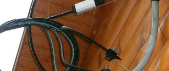
As an example, retro wiring in a wooden house. Although this is not the only case.
Crimping of conductors is a rather large and complex topic, which allows you to create a high-quality connection of electrical contacts. Andrey Kulagin explains its technology well in his video. I recommend watching it.
Where is electric twisting used?
Twisting of wires is performed to connect them electrically and mechanically. This connection method does not imply the transmission of high power. Therefore, they try to use twists only in low-current circuits and rooms without high humidity.
Connecting cables using twisting
Reliable twisting has the following properties:
- Low contact resistance. Otherwise the contact will burn out.
- High mechanical strength. Especially for wires suspended in the air.
- Tightness of the connection. When exposed to water, the twist oxidizes and burns.
- Conformity of metals of current-carrying conductors. Contact between copper and aluminum wires is not allowed.
Methods for connecting wires or cables to each other
The junction of two conductors must meet the following requirements:
- reliability;
- mechanical strength.
These conditions can also be met when connecting conductors without soldering.
Crimping
This method requires special equipment. Crimping of wires with sleeves is carried out for both copper and aluminum wires of different diameters. Depending on the cross-section and material, the sleeve is selected.
Crimping algorithm:
- stripping of insulation;
- stripping wires to bare metal;
- the wires need to be twisted and inserted into the sleeve;
- the conductors are crimped using special pliers.
Selection of a sleeve causes major difficulties. An incorrectly selected diameter will not ensure reliable contact.
Bolted connection
Bolts, nuts and several washers are used for contact. The connection point turns out to be reliable, but the structure itself takes up a lot of space and is inconvenient to install.
The connection order is as follows:
- stripping of insulation;
- the stripped part is laid in the form of a loop with a diameter equal to the cross-section of the bolt;
- a washer is put on the bolt, then one of the conductors, another washer, a second conductor and a third washer;
- the structure is tightened with a nut.
Using a bolt, you can connect several wires. The nut is tightened not only by hand, but also by a wrench.
Terminal blocks
The terminal block is a contact plate in a polymer or carbolite housing. With their help, any user can connect wires. The connection occurs in several stages:
- stripping the insulation by 5-7 mm;
- removal of oxide film;
- installing conductors in sockets opposite each other;
- fixation with bolts.
Pros - you can connect cables of different diameters. Disadvantages - you can only connect 2 wires.
Types of terminal blocks for multi-core and single-core cables
There are 5 main types of terminal blocks:
- knife and pin;
- screw;
- clamping and self-clamping;
- cap-shaped;
- "walnut" type clamps.
The first type is rarely used; they are not designed for high currents and have an open design. Screw terminals provide reliable contact but are not suitable for connecting multi-core cables. Clamp terminal blocks are the most convenient devices to use; their installation does not require special equipment. Cap-type devices are also often used, but unlike clamping devices, caps can be used repeatedly. "Nut" is practically not used.
Terminals in junction box (copper or metal)
Terminals are the most common connection method in a junction box. They are cheap, easy to install, provide reliable contact fixation and can be used to connect copper and aluminum. Flaws:
- cheap devices are of low quality;
- Only 2 wires can be connected;
- Not suitable for stranded wires.
Self-clamping terminal blocks WAGO
There are 2 types of Vago terminal blocks used:
- With a flat spring mechanism - they are also called disposable, since reuse is impossible. Inside there is a plate with spring petals. When installing the conductor, the petal is pressed out and the wire is clamped.
- With lever mechanism. This is the best connector option. The stripped conductor is inserted into the terminal and the lever is clamped. Re-installation is possible.
With proper use, Vago terminal blocks last 25-30 years.
Using Tips
For connection, 2 types of tips and sleeves are used:
- in the first, the connection is made inside the product;
- in the second, two electrical wires are terminated with different tips.
The connection inside the sleeve or tip is strong and reliable. There are also special sleeves for connecting copper and aluminum wires.
Soldering of electrical wiring lugs
The tips are connected to the wiring using a press. If it is not there, contact can be ensured by soldering.
The electrical wire and the tip inside are tinned, the stripped cable is inserted inside.
The entire structure on the contact must be wrapped with fiberglass tape and heated with a burner until the tin melts.
Using Terminal Blocks
The wire connections listed above in any case have certain disadvantages. And twisting is generally prohibited by the rules of electrical installations (PUE), although this method is still in use today. They are unreliable, short-lived, and some methods require special electrical tools or appropriate professional skills.
Not every home craftsman has the soldering skills to connect stranded wires to single-core ones. Although the procedure does not seem so complicated. Moreover, how can it be done when the object is de-energized? Even bigger problems arise when it is necessary to deal with wires made of different metals. They cannot be connected by twisting.
However, despite these difficulties, there is a sure way out, which is to use different terminal blocks. There are a great variety of them today, and they are designed for almost any situation. What can the stores offer?
Useful tips Connection diagrams Principles of operation of devices Main concepts Meters from Energomer Precautions Incandescent lamps Video instructions for the master Testing with a multimeter
Welding fastening
To create the most reliable connection of the conductors after twisting, they are additionally secured by welding. The technology for making such a contact is very similar to soldering, only here a welding machine is used instead of a soldering iron.
In terms of quality and reliability, the welding method fully meets all regulatory requirements for creating electrical contact.
When creating a connection by welding, the conductors are twisted and their tip is welded. The resulting metal ball provides a very reliable connection of the wires. At the same time, reliability is due not only to the creation of high electrical characteristics, but also mechanical ones.
The main disadvantage of this type of wire connection is the presence of a welding machine and devices for such work. In addition, it is necessary to strictly adhere to the rules of working at height and fire safety.
Sequence of welding wires:
- We strip the conductors from insulation by 60-70 mm.
- We clean the cores mechanically (sandpaper).
- We twist the wires, and its length must be at least 50 mm.
- We fix the welding grounding contact on top of the twist.
- Lightly touch the bottom of the twist with the electrode. Wire welding occurs very quickly.
- After the contact ball has cooled, we insulate it.
As a result of such actions, an almost solid conductor is obtained, and the contact node will have the lowest transition resistance.
Types of twists. Errors when twisting
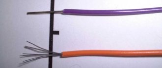
Firstly, remember that wires come in aluminum and copper. Copper wires are divided into monocore (one solid core) and multicore (flexible).
Monocores are used for stationary connection of equipment. Once I laid it under the plaster, behind the drywall and forgot about them. There is no longer any need to move or bend such wiring.
Multi-core cables are used for mobile devices or temporary connection of electrical equipment. Where wiring constantly needs to be moved from place to place, its location must be changed. These are home carriers, household appliances plugged into sockets. They are also used in the assembly of switchboards, where there is a shortage of free space, and the conductors have to be significantly bent in order to be inserted into the terminals of the devices.
Let's first consider how to properly twist wires from a single core. The process here is not complicated and is known to everyone. Take two wires, strip them at the ends and begin to twist each other.
The main features and rules in this process:
- wires must be made of the same material (copper or aluminum)
- strip the core at least 3-4 cm, thereby increasing the useful contact area
- wires are laid parallel to each other
- both wires must be twisted evenly together
- When twisting, use some pliers to hold the place where you start stripping the insulation, and use the other to twist at the end. The insulated parts of the conductors must not be twisted together.
- the number of turns that should end up being five or more
Twists of aluminum and copper wires are performed in the same way. The difference is that you can unscrew and tighten copper ones several times, and aluminum ones 1-2 times. After which they will break off.
What if you need to twist more than two wires, say 4-5? The process is no different:
- slowly twist the wires with your hands, only giving them the shape of the future twist
- take two pliers and, holding the twist at first, tighten the wires at the end
- the length of the stripped areas should also be 3-4cm
There are situations when it is necessary for the twist to take up as little space as possible. Either there is not enough space in the junction box, or it must then be pulled through a narrow hole. In this case, the technology is slightly different.
- place the stripped wire strands crosswise in the middle of the stripping area
- and begin to twist them so that the ends after folding are equidistant from each other
In terms of quality and reliability, such twists are inferior to conventional ones.
Self-clamping terminal blocks WAGO
In addition to terminal blocks with bolts, there are also terminal blocks with clamps. They are more expensive than usual, but they allow the connection to be made much faster, especially in connection with the new requirements of the PUE and the ban on twisting.
The most famous manufacturer of such terminal blocks is WAGO. Each terminal is a separate device with several holes for connecting wires, each of which is inserted into a separate wire. Depending on the version, it connects from 2 to 8 conductors. Some types are filled inside with conductive paste for better contact.
They are available for both detachable and permanent connections.
The stripped wire is simply inserted into the terminals for a permanent connection and spring tendrils fix the wire inside. Only hard (single-core) wire can be used.
In plug-in terminals, the wire is clamped using a folding lever and a spring clamp, making it easy to connect and disconnect wires.
Since the wires do not touch each other, the terminals allow you to connect wires of different sections, single-core to stranded, copper to aluminum.
This method of connecting conductors has proven to work best at low currents and is most widespread in lighting networks. These terminals are small in size and easily fit into adapter boxes.
Original solutions
It is not necessary for everyone to know how to make the correct twist using non-standard solutions, but in some cases it is precisely this knowledge that helps to cope with the work.
For example, how to properly make a twist in which it is necessary to connect not two or three wires, but several dozen pairs? For this purpose, a special mechanical device is used - manual press equipment. This press twists both stranded and single-core wires of the same metal. Sometimes, on the contrary, it is necessary to decide how to properly twist for low-current installations: power cords, LEDs, telephones, etc. For this, special connectors are used, which are plastic caps for twisting wires, inside of which there is a metal alloy plate in a special solution. This is a hydrophobic gel that prevents rust and protects the contact from oxidation and moisture.
If you find an error, please select a piece of text and press Ctrl+Enter
.
Twisting method
The simplest and most well-known method of connecting electrical wires is twisting them (twisting). Experienced electricians often call it the old-fashioned method.
Previously, this type of connection was used everywhere, but with the increase in load in the electrical network of a modern apartment, twisting became prohibited. However, this connection method must be studied first, since it is the main step in soldering and welding wires.
The main advantage of twisting is the absence of any material costs, since you only need pliers and a knife to remove the insulation. And of course, the advantage of twisting is the ease of its execution. Anyone who has held pliers in their hands can do this job without any problems.
Over time, the twist weakens, which is its main disadvantage. This process is connected with the fact that in any veins there is residual elastic deformation. Therefore, at the point of twisting, the contact resistance increases, which leads to weakening of the contact and heating of the conductor. It’s good if this defect is discovered in time and the joint can be redone, but a fire may occur.
But if for some reason you do not have the opportunity to use more reliable methods, then you definitely need to familiarize yourself with how to properly connect the wires to each other using the twisting method. To do this, you first need to strip the cores of 70-80 mm of insulation. Then, holding both conductors where the insulation ends, use pliers to grab the ends of the wires and rotate them clockwise. The main condition for reliable twisting is the simultaneous rotation of the conductors, and not alternately winding them on each other.
If the diameter of the wires is small, then twisting can be done entirely by hand. With your left hand you need to hold the conductors along the cut of the insulation, and with your right hand you need to rotate the conductors by the bend (10-15 mm) clockwise. For tighter contact at the end of the rotation, you can use pliers.
The next step is to insulate the junction of the wires. Insulating tape is used for this. To ensure reliability and protect the contact from moisture, you need to wind the tape in several layers, with 2-3 cm of overlap between the wire insulation. A very good option for insulation is the use of thermal tubes; the main thing is not to forget to put it on one of the cores.
Professional electricians advise not to stop at the stage of twisting the wires, but to strengthen the joint by soldering or welding.
Tips that will be useful to you
If you want to be sure of the quality of the connection you made, we recommend that you familiarize yourself with the following recommendations:
- Have you twisted the wires, but the twisting does not seem reliable to you? Use soldering or welding! Such a connection will simply become unbreakable and you definitely won’t have to worry about the quality of contact between the cores. By the way, this option is most acceptable when the wire cores have a large cross-section.
- Use terminals, for example - WAGO. They will not only provide a reliable connection, but will also allow you to make it much faster. Which is also very convenient - using terminals it is quite possible to connect several wires, both with different sections, and even made from different metals. The contact will be more reliable than ever. Terminals are also an excellent option for connecting wires in a chandelier or outlet.
- Use PPE clamps. Their task is not only to make the connection reliable, but also to increase its security. In addition, such PPE caps are not at all expensive.
- Did you twist the wires together? Don't rush to hide the connection in a junction box! Let the new electrical circuit unit operate for some time. After this, you will need to check the temperature of the wires where they are connected. If you feel that the wires are heating up, you should definitely redo the twisting!
Use these tips, they will definitely not interfere with you when performing any electrical work where there is a need to connect wires to each other
What is important to pay attention to is that the above methods do not make the twist waterproof. So if you are planning to fasten the conductors in the wall under a layer of plaster (and without a box), be sure to insulate the joints with cambrics
Is it possible to connect cables by twisting?
According to the rules of the PUE, twisting is prohibited, as it does not provide reliable contact. It can only be used in conjunction with another connection method. It is also unacceptable to use twisting to join two different metals.
Stranded and single-core
When connecting multi-core wires, the following rules should be followed:
- strip the insulation by 4 cm;
- unwind the conductors by 2 cm;
- connect to the junction of untwisted conductors;
- twist the wires only with your fingers;
- You can tighten the twist using pliers;
- bare wires are insulated with special tape or heat shrink tubing.
Twisting solid wires is much easier. They need to be stripped of insulation, twisted by hand along the entire length, then clamped with pliers and insulated.
Twisting methods
You can do twisting in different ways. It can be made by branch, parallel or series connection. Also, to improve the reliability of contact, caps and clamps are additionally used.
Correct twisting of electrical wiring in a junction box
When twisting, you need to follow the following procedure:
- cut off power to a house or apartment;
- clear the wiring of 4 cm or more of insulation;
- unwind the wires by 2 cm;
- connect untwisted wires to the junction;
- twist the veins with your fingers;
- tighten the twist with pliers;
- insulate exposed wires.
Both single-core and multi-core cables can be connected.
Twisting of different sections
Do not twist wires with very different diameters. Such contact is not reliable and stable. You can twist wires of adjacent sections - for example, 4 sq. mm and 2.5 sq. mm. When twisting, you need to make sure that both wires wrap around each other. A thin wire should not be wound onto a thick one, otherwise the contact will be unreliable. Then you need to solder or weld the joint.
Twist caps
The caps help to reliably insulate the contact point. The cap is made of fire-resistant material, inside it there is a metal part with threads.
Making twists using caps is quite simple - you need to remove 2 cm of insulation and lightly twist the wires. A cap is put on them and turned several times until the metal wires are inside.
With terminal clamps
The contact clamp consists of a screw, a spring washer, a base, a current-carrying core and a stop that limits the spreading of the aluminum conductor. Making a connection using a contact clamp is simple - just strip the ends of the wires by 12 mm and insert them into the hole in the clamp. Contact clamps are used for both solid and stranded conductors.
After twisting, the wires need to be soldered. To do this, the wires are tinned and rosin is applied to them before twisting. The heated soldering iron is lowered into the rosin; it needs to be passed along the stripped part of the wiring. After twisting, take tin on a soldering iron and heat the joint until tin begins to flow between the turns. This method takes a lot of time, but it is reliable and of high quality.
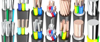
Design difference
Let's figure out what determines the flexibility class of cables.
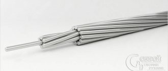
A single-core wire has a monolithic core of one wire of the required nominal cross-section. The limit of resistance to bending before breaking is different for different materials. Copper can withstand about 80 bending cycles; for aluminum this figure rarely exceeds 10. This is the first class of flexibility.
The core of a multicore cable is made up of a large number of thin wires twisted together, the sum of the cross-sections of which forms the nominal value. The cross section of the core resembles the design of a metal cable. The number and thickness of the wires determine the degree of flexibility. The maximum number of bending cycles reaches more than 30,000 for grade 5 copper conductors.
A soft cable is convenient for connecting the terminals of sockets and lamp sockets, where the monolith often breaks off. It is convenient to turn on the cooking surface of the electric stove, which has to be moved when cleaning. Permanently connect a washing machine that vibrates during operation to the network.
Tips from experienced installers
There are many controversial issues both in connection methods and in the use of individual mounting products. But a number of rules apply to absolutely all craftsmen who do electrical installations.
For example, it is strictly prohibited to twist aluminum conductors with copper ones. The process of rapid oxidation leads to the destruction of the commutation and the creation of a dangerous point, which can spark or flare up at any time.
A few more important rules:
Image gallery
Photo from
Properly executed twisting
Maximum connection isolation
The importance of marking conductors
If the conductor is covered with an oxide film, it must be carefully removed using either contact paste or fine sandpaper. It is better to select the diameters of sleeves, tips, caps according to size.
When using electrical tape, overlap the wraps. One layer is not enough, it is better to go along the connection 2-3 times, making sure to make the last turn on the insulation
Single conductors in screw terminals are held loosely. Therefore, it is recommended to bend the stripped end in half or make an arbitrary loop out of it.
At the end of the work, be sure to check the reliability of the connections - lightly tug the wires. It happens that the switching is unsuccessful, and the core simply slips out of the terminal block.
If the volume of the distribution box allows, for example, the panels accommodate a lot of wires and devices, then leave the cable with a reserve. Sometimes switching is required and the extra length is useful if the connections are permanent or burnt.
Features of connecting different wires
Most people who have at least some relation to electrical installation work are aware of the fact regarding the junction of copper and aluminum wires: it is not recommended to connect them. However, many people know about this, but they do it anyway: maybe they’ll hold out somehow.
As a result, it turns out that copper-aluminum twisting lasts a very, very short time. If the connection is placed outdoors or in a room with high humidity, the service life of such a pair is significantly reduced.
But situations in which it is necessary to connect copper and aluminum wires are far from uncommon. In particular, this phenomenon has practically become the rule when carrying out repair work in rooms with aluminum wiring.
In such cases, the solution to the problem will be specially made terminal blocks or bolt-type connections, through which contact between the copper and aluminum wires will be made. By using a clamped or bolted connection, direct contact between the two metals is eliminated. Let's consider the most popular options for such connectors, without delving into the design details.
Perhaps one of the earliest and most tested methods is to use a nut-type terminal connection. As you might guess, the reason for the name was the external similarity of the shape of the adapter to a nut.
The design of such a connection consists of three plates that clamp the wires together. The advantage of this type of connection is that there is no need to break the main line to install the outgoing wire. You just need to unscrew a couple of bolts, insert the desired wire between the plates, and then return the bolts to their place. The outgoing wire is allocated a place between the middle and third plate. Once it's in place, the connection is effectively complete.
In second place in popularity are spring-type express connection terminals. As the name suggests, their use provides maximum connection speed. Indeed, to make the connection, you only need to strip the ends of the copper and aluminum wires, and then insert them into the holes and fix them.
Inside such a terminal block there is a special lubricant that prevents the oxidation of the wires. It should be noted that such adapters are most suitable for lighting circuits or other areas with low load. For example, using it in a power circuit can cause the contact to overheat and break.
Terminal blocks have also found quite wide application. It looks like a strip on which the terminal blocks are located. To connect a wire to it, you need to strip the conductor and then fix it in the hole using a mounting screw. Accordingly, another wire is inserted into another hole.
Let’s assume an option in which wires made of copper and aluminum will be connected with a bolted connection. To do this, it is necessary to place a special anodized washer on the bolt between conductors of different metals, which prevents direct contact of the materials.
It should be borne in mind that installation work should be carried out by specialists of the appropriate profile. In the future, you should regularly check screw and bolt connections: for aluminum wires this is twice a year, for copper sections - once every 2 years.
GOST classifications and requirements
Wire connectors are any devices that serve to close/open an electrical circuit. These can be electrical installation products - sockets, switches, as well as metal bars and plates, lugs, terminals and terminal blocks - blocks with several sockets.
We will focus on connectors in a narrower sense - on elements that create detachable and non-separable connections and ensure their reliability and functionality - that is, on all kinds of terminals, terminal blocks and sleeves.
The simplest example of a lug for a stranded wire. The terminal is a metal sleeve-tube fixed at the end of the conductor using crimping pliers
Terminals are called both metal elements for decorating the ends of single- and multi-core wires, and small plates inside connecting devices - sockets, terminal blocks, patch panels.
The terminals differ in material, shape and size, but are similar in purpose - they provide mechanically strong switching of two or more wires, without electrical losses and installation difficulties
The classification of electrical connectors is presented in GOST 10434-82 , which provides information on the division into classes (1, 2, 3) and groups (A, B). Also, according to standards, contact connections are divided into detachable and permanent, requiring stabilization or working without it.
Some recommendations may be useful not only to professionals, but also to home craftsmen who install their own electrical wiring.
For example, it talks about the most preferred methods of connecting aluminum plates - soldering or welding and aluminum tips - crimping or welding.