How to determine phase, zero and grounding yourself, using improvised means?
Anyone doing electrical work at home or simply deciding to install a chandelier, sconce, or connect an outlet will definitely be faced with the question - how to determine the phase, neutral and grounding of the wires at the installation site?
In our articles and instructions, we often post connection diagrams, rules for installing and connecting electrical equipment to the network, as well as much more, where in order to correctly perform all operations you need to know where your phase wire is, where the neutral (working zero) is, and where the ground wire is (protective zero). For an experienced electrician, determining where the phase and zero are or finding the ground is usually not difficult, but what about the rest?
Let's try to figure out how at home, without having complex specialized measuring instruments and electronic devices, you can determine for yourself where the phase is, where the zero is, and where the ground is in the wiring.
Of all the known methods, the simplest determination of phase and zero, we have selected the most, in our opinion, accessible to implementation and at the same time safe. For this reason, in the article you will not see advice on how to find the phase using potatoes or calls for briefly touching the wires with various parts of the body.
What are distribution boxes for?
There are many factors that speak in favor of the existence of junction boxes:
- The power system can be repaired in a matter of hours. All connections are accessible, you can easily find the area where the wires have burned out. If the cable was laid in special channels (corrugated tube, for example), then the failed cable can be replaced in an hour;
- Connections can be inspected at any time. As a rule, wiring problems occur at the connection points. If the socket or switch does not work, but there is voltage in the network, first check the quality of the connection in the junction box;
- the highest level of fire safety is created. It is believed that dangerous places are connections. Using a box will keep them in one place.
- minimal time and financial costs when repairing wiring. There is no need to look for broken wires in the walls.
Wire marking by color
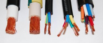
Indeed, the easiest way to determine the phase, neutral and ground of an electrical wire is to look at the color marking and compare it with the accepted standard. Each core in modern wires used in electrical wiring and electrical equipment has an individual color. Knowing which color of cores corresponds to which function (phase, neutral or grounding), you can easily carry out further installation.
Quite often, this is quite sufficient, especially in cases where the installation is carried out in new buildings or places with fairly new electrical wiring, made by professional, competent electricians in accordance with all modern rules and standards.
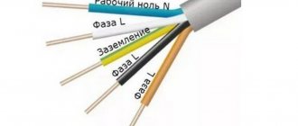
According to this standard for residential electrical networks:
Working zero (neutral or zero) - Blue wire or blue-white
Protective zero (earth or grounding) - yellow-green wire
Phase – All other colors including black, white, brown, red, etc.
Now, knowing the standard for color marking of wires, you can easily determine which wire performs which function. This applies to most cases, the exception may be wires suitable for switches, switches, etc., due to the fundamentally different operating scheme of this electrical equipment.
HOW TO DETERMINE PHASE, ZERO and GROUNDING OF WIRES YOURSELF
So, let's start in order:
PHASE DETERMINATION
For greater convenience, it is always better to first determine which of the existing wires is phase. We have already written about how to find the phase with a digital multimeter, but what to do if you don’t have one, read below.
PHASE DETERMINATION WITH AN INDICATOR SCREWDRIVER
The easiest way to detect a phase wire is to search with an indicator screwdriver. Any home craftsman who does electrical work in an apartment should have this simple tool - be it full electrical installation, simple replacement of lamps or installation of lamps, sockets and switches.
The operating principle of an indicator screwdriver is simple - when the tip of the screwdriver touches a live conductor and at the same time touches the contact on the back of the screwdriver with your finger, the indicator lamp in the tool body lights up, which signals the presence of voltage. This way you can easily find out which wire is phase.
The operating principle of the indicator screwdriver is simple - inside the indicator screwdriver there is a lamp and a resistance (resistor), when the circuit is closed (we touch the rear contact) the lamp lights up. Resistance protects us from electric shock; it reduces the current to a minimum, safe level.
DETERMINATION OF PHASE, ZERO AND GROUNDING BY CONTROL LAMP
Another way in which you can determine the phase, neutral and ground wires in a modern three-wire electrical network is by using a test lamp. The method is ambiguous, but effective, requiring special care.
To begin the determination, you first need to assemble the control lamp device itself. The easiest way is to use a socket with a lamp screwed into it, and secure the wires with the insulation removed at the ends into the terminals of the socket. If you don’t have an electric socket at hand or don’t have time to make something, you can use a regular table lamp with an electric plug.
The technology for determining phase, zeros and ground using a test lamp is as simple as possible - alternately connecting the lamp wires to the wires requiring determination, each with each.
Determine the phase and zero of two wires
If the test lamp detects a phase wire among two wires, you will only be able to find out whether there is a phase or not, but which of the conductors is the phase wire cannot be determined. If, when connecting the wires of the test lamp to the identified wires, it lights up, then one of the wires is phase, and the second is most likely zero. If it doesn’t light up, then most likely there is no phase among them, or there is no zero, which also cannot be ruled out.
In this way, it is rather more convenient to check the functionality of the wiring and the correctness of its installation. It is better to determine the phase with an indicator screwdriver, but to find out the presence of zero this way.
In this case, you can determine the phase wire by connecting one of the ends coming from the control lamp to a known zero (for example, to the corresponding terminal in the electrical panel), then when the other end touches the phase conductor, the lamp will light up. The remaining wire is correspondingly zero.
Find phase, neutral and ground from three wires:
In such a three-wire system, it is often possible to accurately identify the phase, neutral and ground wires with a test lamp. We connect the contacts coming from the control lamp one by one to the cores of the cable requiring identification.
We use the elimination method:
We find the position in which the lamp is lit, this will mean that one of the wires is phase and the other is zero.
Then we change the position of one of the contacts of the control lamp, then several options are possible:
— If the lamp does not light up (if there is an RCD or differential circuit breaker of the line being tested, they can also work), then the remaining free wire is PHASE, and the ones being tested are ZERO and GROUND.
— If after changing the position the lamp flashes briefly, the RCD or differential will immediately trip. machine (if they exist), then the remaining free wire is ZERO, and the ones being tested are PHASE and GROUND.
— If the line is not protected by a residual current device (RCD) or a differential circuit breaker, and the light will light in two positions. In this case, you can find out which wire is the working zero (zero) and which is the protective wire (grounding) by simply disconnecting the input cable from the grounding terminal in the electricity metering and distribution panel. Then also check all the wires with a test lamp and, again by elimination, in the position when the lamp is not lit, identify the grounding conductor.
As you can see, in different situations, with different electrical wiring diagrams implemented in the apartment, the methods and methods for determining zero, phase and grounding change. If you encounter a situation not described in this article, be sure to write in the comments to the article, we will try to help you.
And if you also know simple ways to determine phase, zero and ground at home, without a specialized tool, write in the comments. The article will definitely be updated. The main requirement for determination methods is simplicity, the ability to do the search only with improvised, household means that many people have.
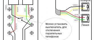
How to connect a switch with one key
If there is a switch in the room, then the connection in the box will be a little more complicated than with only sockets. There will also be three groups of conductors, but the connection is of a different type. Available:
— input cable – from another box or directly from the switchboard;
— wire for the chandelier;
- wire from the switch.
The circuit should work as follows. Power (that is, phase) is supplied to the switch key. From its output a wire is supplied to the lighting fixture. As soon as the switch contacts close, the chandelier will light up. The ground and neutral wires must be twisted together.
Why do we need color coding for wires and cables?
Installation and maintenance work in electrical installations is associated not only with ensuring reliability, but also safety. Complete error elimination is required. For these purposes, a system of color designations for core insulation has been developed, which determines what color the wires are phase, neutral and ground.
According to the PUE, the following colors of current-carrying conductors are allowed:
The above list contains many options for wire colors, but there are not several colors that are used only to indicate neutral and protective wires:
- blue color and its shades - working neutral wire (neutral - N);
- yellow with a green stripe - protective earth (PE);
- yellow-green insulation with blue marks at the ends of the conductors - combined (PEN) conductor.
It is allowed to use conductors with green insulation with a yellow stripe for grounding, and for combined conductors blue insulation with yellow-green marks at the ends.
The color must be the same in each circuit within one device. Branch circuits must be made with identically colored conductors. The use of insulation without differences in shades indicates a high standard of installation and greatly facilitates further maintenance and repair of equipment.
Tile cutting device
It's been a while since I added anything here.
Preface: why exactly this way, and not using a machine.
Firstly, I’m not entirely sure that the so-called wet tile cutter will cope with this task, and I’m sure that a cheap one definitely won’t cope, and an expensive one, let’s say from 50 thousand rubles. Maybe he can handle it, maybe he won’t.
Therefore, with such a daisy, I refused to buy an expensive machine because the work will not pay for such costs, and cheap rubbish is not needed.
This means we work the old way, proven and cheap.
In general, I have a tile cutter, it’s not the worst, it successfully coped with various tasks, but there was a problem with this porcelain tile. It (porcelain stoneware) breaks off along the cut line completely uncontrollably, it can clearly break, or the arrow can go to the side. The second problem is that the surface is very fragile, just like a glass surface; even behind the roller, chips can occur. A diamond cup can also chip even with a light touch. There is no need to talk about a diamond disc at all, the surface after it is jagged and chipped, which means that not every water-powered tile cutter can cope with such a task.
Coloring phase
In cases where the electrical installation is installed using rigid metal busbars, the tires are painted with indelible paint in the following colors:
- yellow - phase A (L1);
- green - phase B (L2);
- red - phase C (L3);
- blue - zero bus;
- longitudinal or inclined stripes of yellow and green color - grounding bus.
The color of the phases must be maintained throughout the entire device, but not necessarily over the entire surface of the bus. It is allowed to mark the phase designation only at the connection points. On a painted surface, you can duplicate the color with the “ ZhZK ” symbols for paint of the corresponding colors.
If tires are not accessible for inspection or work when there is voltage on them, then they may not be painted.
The color of phase wires connected to rigid busbars may not coincide with them in color, since there is a difference in the accepted designation systems for flexible conductors and rigid stationary distribution busbars.
Which fork is better - collapsible or cast?
The cast plug is more reliable; its main advantage is the density of the contacts that connect to the pins. The cast model uses spot welding, soldering and crimping. Another advantage of the model is its tightness.
But there are annoying drawbacks: it cannot be disassembled to eliminate the cause of the breakdown. If the cord frays at the base due to prolonged use, then the only solution is to cut off the molded plug to replace it with a collapsible model. It is possible to completely change the cord and plug to a new one, but to do this you will have to disassemble the device.
However, if such a replacement does not frighten you, it is better to purchase a cast product, especially since, due to its increased reliability, such a fork fails much less often than its collapsible counterparts.
Neutral color
What color the neutral wire is is specified by GOST , therefore, when looking at the installation of a power plant, the question should not arise whether the blue wire is a phase or a zero, since the blue color and its shades (blue) are accepted to indicate neutral (working grounding).
Other colors of neutral cores are not permitted.
The only acceptable use of blue and cyan insulation is to indicate the negative pole or midpoint in DC circuits. This color cannot be used anywhere else.
Ground wire color coding
The rules indicate what color the ground wire in electrical installations is. This is a yellow-green wire, the color of which stands out well against the background of the other wires. It is acceptable to use a wire with yellow insulation and a green stripe on it, or it can be green insulation with a yellow stripe. It is not allowed to use any other color of the ground wire, just as it is not allowed to use green-yellow conductors for installing circuits on which voltage is present or may be applied.
The listed labeling rules are observed in the countries of the post-Soviet space and in the countries of the European Union. Other states mark the cores in a different way, which can be seen on imported equipment.
Basic colors for marking abroad:
- neutral - white, gray or black;
- protective grounding - yellow or green.
Standards in a number of countries allow the use of bare metal without insulation as protective grounding.
Grounding wires are switched on prefabricated non-insulated terminals and connect to each other all metal parts of the structure that do not have reliable electrical contact with each other.
Design features
The design of electrical plugs is divided into several types. You need to familiarize yourself with the technical characteristics, advantages and disadvantages of each in more detail.
Non-removable fork device
The design features of non-separable modifications are the same everywhere. The pins are installed at intervals of 19 mm into a strip made of plastic; conductors are pressed into it. The bar is equipped with two protrusions, the purpose of which is to guide the wire. The bypass is important because it eliminates the possibility of the plug cord breaking if significant force has been applied to it.
The wire and pins are filled with molten plastic. This is ensured by a high degree of tightness of the case with the power cord securely fixed in it.
Device of a collapsible three-pole design
Not so long ago, only collapsible structures were used to connect electrical appliances. Today they are still used by a large number of Russians. You cannot do without such a part if you need to replace a cast mechanism that has failed. The advantage of such a fork is its maintainability and the ability to use it repeatedly. It can be dismantled and installed on another cord without much effort.
Design device type C1-B
This design is incredibly simple in its implementation. It consists of two halves of a plastic body, two brass pins, fasteners and a clamping bar.
Design features of the collapsible structure type C6
The design is also not particularly complicated. Modifications are available with or without a grounding contact. Designed to operate devices with a power of no more than 220 W. The pins are made of brass; contact pads with threads are pressed onto them for screwing wires. The pins are attached to the base of the plug. An additional grounding contact can be installed in the housing, which has the shape of a brass strip. There is also a strip for securely fastening the wire with a plastic gasket.
Colors for 220V and 380V networks
Installation of single- and three-phase electrical networks is facilitated if the wiring is made with multi-color wire. Previously, a flat two-core white wire was used for single-phase residential wiring. During installation and repair, to eliminate errors, it was necessary to ring each core individually.
The production of cable products with colored cores in different colors reduces the labor intensity of the work. To indicate phase and zero in single-phase wiring, it is customary to use the following colors:
- red, brown or black - phase wire;
- other colors (preferably blue) - neutral wire.
The phase markings in a three-phase network are slightly different:
- red (brown) - 1st phase;
- black - 2 phase;
- gray (white) - 3 phase;
- blue (blue) - working zero (neutral)
- yellow-green - grounding.
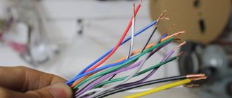
Domestic cable products comply with the standard for core coloring, so a multiphase cable contains differently colored cores, where the phase is white, red and black , the neutral is blue , and the ground is yellow-green conductors.
When servicing networks installed according to modern standards, it is possible to accurately determine the purpose of the wires in the junction boxes. If there is a bundle of multi-colored wires, the brown one will definitely be phase. The neutral wire in distribution boxes has no branches or breaks. The exception is branches to multi-pole switching devices with complete circuit breaking.
Coloring in DC networks
For DC networks, it is customary to mark conductors connected to the positive pole in red, and to the negative pole in black or blue. In bipolar circuits, blue insulation is used to mark the midpoint (zero) of the power supply.
There are no standards for color codes on multi-voltage circuits. What color are the plus and minus wires, what voltage is in them - this can only be determined by the decoding of the device manufacturer, which is often given in the documentation or on one of the walls of the structure.
Example: computer power supply or car wiring.
Automotive wiring is characterized by the fact that in it the circuits with positive voltage of the on-board network are red or its shades (pink, orange), and those connected to ground are black. The remaining wires have a specific color, which is determined by the car manufacturer.
Modern technologies
In many cases, the methods discussed are gradually becoming a thing of the past. They were replaced by factory wire connectors, which made installation and switching work much easier and faster:
- Terminal blocks, inside of which there are tubular brass sleeves. Stripped wire strands are inserted into these tubes and secured by tightening the screws.
- PPE caps, inside of which there are compression springs. The cores are inserted into the cap and then turned clockwise with little effort, thereby reliably compressing the connected wires inside.
- Self-clamping terminals. It is enough to place the wiring in them, and there it is automatically fixed due to the pressure plate.
- Lever-type terminal blocks. This connecting element is reusable. It is enough just to lift the lever, insert the conductor into the contact hole and lower the lever back, reliable fixation is ensured.