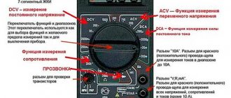
Locating cable damage
As a rule, consumers are connected to power sources (transformer and distribution substations) using cable lines (CL). This is due to the fact that this method has many advantages over overhead lines (OL). But, if there is an accident on the cable line, then finding the location of the cable damage without special instruments is almost impossible. Today we will look at several ways to localize an emergency section of a cable route laid in the ground.
Damage detection techniques
To complete the assigned task, you need to know the technical part of the search and the physical principles on which they are based.
The process itself is divided into two components:
- Searching for the damaged area.
- Searches for a point in a designated area.
But not only the stages of work are different, but also the methods used in them; according to this principle, they are divided into:
- relative – loop and pulse;
- absolute – step voltage, induction and acoustic methods.
Pulse method
This technique involves the use of a reflectometer. Let's look at the instructions using the example of REIS-305, which is a fairly common device.
The device itself is based on the principles of probing pulses. Moving at certain frequencies along the conductor, they encounter an obstacle and then return back. By placing the device at one end, you can determine the exact distance to the gap using the formula: L=(tx/2)*υ, where L is the required distance, tx is the time spent by the impulse on the two-way road, and υ is the speed at which it moves pulse.
This method is excellent for both searching for breaks and determining a short circuit between the cores; the essence of the problem will be displayed on the device display.
Loop technique
Not the most perfect method, it can only be used when there is at least one intact core, or there is at least one known intact conductor nearby. The loop method involves measuring direct current resistance in an artificially closed loop, the length of which is known to the person performing the procedure. An example of equipment is the P333, a special measuring bridge.
The ends of the conductors are wound, and the others are connected to the device and the result is calculated using the formula: L=(2Lk*R2)/(R1+R2), in which R1 is the result of the whole core, R2 is the wire with a break, and Lk is the length of the entire damaged conductor .
Acoustic technique
This approach does not contain complex physical calculations, everything is much simpler:
- a high-voltage current is connected to the damaged power cable using a high-voltage discharge generator;
- after which they take a listening device and follow the network line in order to find the noise corresponding to the location of the break.
Despite its apparent simplicity, this approach has three significant drawbacks:
- soil features may make work impossible;
- Absolutely not applicable on deep power grids;
- The transition resistance should not fall below 40 ohms.
Step voltage
This study is based on measuring potential differences. With the help of a generator, a current is passed through the conductor, at the point of break it creates a corresponding difference. To find a specific point, two measuring pins are installed perpendicular to each other: one exactly above the conductor, and the second a meter from it.
Induction method
This method can quickly and reliably find mechanical damage, but it has one significant drawback - burning the cable. If this moment does not stop you, then you can start. You can use VUPK-03-25 as a device.
A high-frequency current is passed through the core; it forms an electromagnetic field, which is recorded by the receiving frame. In the area where the measurements become zero, a gap has occurred.
Causes and types of damage to cable lines
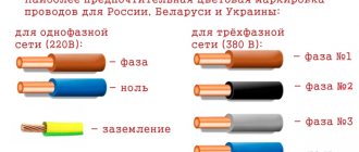
There are many factors that negatively affect the integrity of power cables, the most common of which include the following:
- Ground movement can be caused by a failure of water supply, sewer or heating networks, as well as seasonal phenomena, for example, spring thawing.
- Exceeding the permissible operating standards for cable lines, which can lead to thermal overload of the line caused by an increase in current load.
- Formation of a high level of electric current in the cable line from a transit short circuit.
- Mechanical damage during excavation work without taking into account the passage of underground communications and the depth of the route.
- Errors when laying cable lines. As an example, we can cite violations of the technology for connecting cores with cable couplings.
- Manufacturing defects.
Note that when cable routes are laid open, some of the above causes of damage are extremely rare. In particular, the likelihood of the influence of soil movement and mechanical impacts due to excavation work is reduced. In addition, damage zones of open cable lines, in most cases, can be detected by visual inspection, without the use of special methods.
Having dealt with the reasons, let’s move on to the types of damage, since this directly determines the method by which the emergency section of the cable line will be localized.
Most often, repair teams have to deal with the following types of faults:
- A defect caused by a complete or partial break of a cable line. Most often, the cause of the accident is excavation work without determining the passage of cable routes. Somewhat less frequently, the cause of this damage can be a short circuit in the couplings.
- In power cables (more than 1 kV), breakdown of one of the conductors to ground (single-phase short circuit) is often encountered. Leakage current, as a rule, is caused by a decrease in the quality of insulation during operation of the cable line.
- Interphase damage, as well as types of metal short circuits, can occur in any lines; the cause of damage is the same as in the previous paragraph.
- Routine cable testing, which involves high voltage levels, shows low insulation reliability and leads to breakdown. Under certain circumstances, such a line can continue to operate, but due to its low level of reliability, an accident can occur at any time.
Also, according to the type of damage, lines should be divided into several types:
- destruction of insulation, resulting in a short circuit of one or more phases to ground;
- damage causing phase short circuits between each other or the screen;
- break of one or more wires;
- broken screen or neutral wire;
- CL damage in several places.
Typically, the causes of mechanical damage are repair or construction work carried out in the area where the line is laid. And to a lesser extent, insulation burnout occurs due to poor-quality connections in the couplings, at the site of which sparking and further thermal destruction of the insulation occurs. If a broken line can be eliminated by simply inserting one coupling, then if it burns out, you may have to replace an entire section of the line.
Briefly about cable line repair
Repair work on cable lines is usually classified into planned and emergency. As for the volume of such work, for the former it is, as a rule, capital, for the latter it is current.
During major works, planned replacement of cable lines, laying of new routes, etc. are carried out. If necessary, repairs and/or upgrades of related equipment are also performed. The latter include ventilation systems and lighting for cable tunnels, as well as pumps for pumping out groundwater. Considering the specifics of planned work, localization of defective areas is not required during their implementation.
The situation is completely different during emergency repairs. In order not to dig up the entire route, you should accurately determine the location of the wire break, insulation breakdown, etc. For this purpose, various methods are used, for which special equipment is used. This will be discussed in detail below.
The principle of searching for MP (maximum method)
The search process must begin from a point known to be located before the MP. The operator positions the A-frame so that the line connecting the pins is perpendicular to the communication route. The pins are buried in the ground so that one of the pins is located exactly above the route. Using the A-frame divider and receiver gain controls, the signal level on the receiver indicator is set to about 25% of full scale. Next, the A-frame moves a certain distance, for example 1 m, along the route towards the MP. The pins are buried in the ground in the same way. It is necessary to try to ensure that with each step the pins are immersed in the ground to the same depth, since the signal level significantly depends on the depth of immersion. Such step-by-step movement when approaching the MP will be accompanied by a significant increase in the level of the displayed signal. If the signal level exceeds the limits of the indication scale, you must use the receiver gain control to set it, as at the beginning of the search, within 25% of the full scale. The maximum signal will be achieved directly in the MP.
The principle of searching for MP (maximum method)
Methods for determining cable damage in the ground
As a rule, cable flaw detection is carried out in two stages:
- The boundaries of the zone within which the emergency area is located are established.
- A search is made for the exact location of the damage in a certain area.
Accordingly, at the first stage, relative methods are used, and at the second stage, technologies with increased accuracy of damage detection are widely used. Let us list the main flaw detection techniques and the features of their application.
Induction method
This technology allows you to determine the location where the breakdown of the insulating layer of the conductive elements of the cable occurred. To do this, using a special generator, an alternating current with a power of up to 20.0 amperes and a frequency of 800.0 to 1200.0 hertz is supplied to the cable line. As a result, an electromagnetic field of a certain intensity is formed around the CL. If you place an antenna frame connected to headphones through an amplifier, you can hear a sound of a certain frequency above intact conductive elements.
By the nature of the sound signal, it is possible to determine not the location of the defect, the position of the couplings for connection, the topography of the route (tracing), including the presence of protective pipes. Below is a figure that shows the level of signal change over different sections of the cable line.
Finding cable faults using the induction method
Designations:
- Master oscillator.
- Location of connecting elements.
- Cable protection.
- Defective location.
Pulse method
As mentioned above, this method is relative, that is, it allows one to identify the defective damage zone (usually an interphase short circuit). The principle of operation is to apply a reference high-voltage pulse to the cable line using a special device and then determine the distance to the emergency area from the reflected pulse current signal.
Screen of the IKL device displaying the reflected pulse in the event of a short circuit (a) or a break (b) of the cable
In the example shown in the figure, the distance to the defective area is determined as follows:
tx – time interval between the sent and reflected electrical signal, measured in microseconds. As can be seen from the figure, it is equal to 3.5 μs. Considering that the pulse propagation speed (v) is approximately equal to 160.0 m/µs, then to solve it is necessary to apply the following formula: lx = ( tx*v ) / 2, where lx is the distance from the pulse generator to the damaged section of the cable. As a result, we get (3.5 * 160) / 2, that is, 280.0 meters.
Please note that in some devices the shape of the reflected signal can be used to judge the nature of the defect.
Acoustic method
The technology is based on the formation of spark discharges in the defective area, accompanied by sound pulses. You can fix them using a regular stethoscope, placing the acoustic head to the ground, or using a special acoustic receiver. Above the defective area, the sound frequency discharges will be as loud as possible.
Various schemes used in the acoustic method of searching for cable faults
Designations:
- Search for a stable short circuit between the current-carrying core and the cable sheath.
- Scheme for searching for floating breakdowns.
- The use of efficient conductive elements (the capacitance of the conductors is involved).
- Scheme for finding a cliff.
Video on the topic:
Capacitive method
The technology of this method allows you to search for damage, in particular a break in the current-carrying elements of the cable, by measuring the capacitance of the cores. As you know, this parameter directly depends on the length of the cable. A simplified circuit of high-voltage oscillations for such a device can be found below.
AC bridge used in capacitive cable fault detection method
Designations:
- R1, R2, R3 – adjustable resistors.
- Ce – standard high-voltage capacitor.
- L – distance to the break point.
- Lк – total length of the cable line.
- 1 – current-carrying elements of the cable.
- 2 – protective shell.
- 3 – break point.
Finding the break point
With the help of such homemade devices, you can find the location of a hidden wiring break. If a contact break is detected, the device will stop beeping, the nature of the noise will change, or the indicator light will go out. However, these devices have one significant drawback: cable detection is impossible if the hidden wiring is located at a depth of more than 5 cm.
But if fittings or other metal elements pass through the wall, then detecting hidden cables becomes difficult, because false signals will appear. This needs to be taken into account.
For the most accurate search for a broken hidden wiring, finders are used that have the possibility of additional settings, which allows you to ignore large metal objects in the wall. This function eliminates the sending of false signals. If there is direct access to the entire length of the wiring, then the damaged area is often visible to the naked eye. In the case where there is no visible damage, searching for the location of the electrical wiring break can be done using a conventional tester. The algorithm of actions will be as follows:
- first of all, it is necessary to de-energize the room by turning off the electricity supply in the electrical panel;
- then you need to strip the wire in two places: at the outlet of the distribution block and at a distance of 1 meter from the notch made;
- on this segment the resistance is measured, then another notch is made after 1 meter and the procedure is repeated;
- The resistance at all measured intervals must be the same. When the device finds an area where the value is very different or completely absent, a break occurs in this place.
If it is not possible to buy a special finder, but there is a great desire to solve the problem without outside help, you can assemble a primitive device for searching for broken wiring with your own hands.
All you need is a working socket, a light bulb, two single-core wires, a knife, pliers and electrical tape.
A light bulb is screwed into the socket and the wires are connected. From the other ends, the insulating material is stripped 4-5 mm from the edge.
Detecting a wire break involves connecting the tester to the wire being tested, which must be cut with a knife (before stripping the cable, you must turn off the power supply).
https://youtube.com/watch?v=zNSVKAwadZw
If you find an area where the light on the tester does not light up, you need to start moving in the opposite direction, making notches at a shorter distance. After finding the desired location, the damaged section of the wiring will be replaced, all cuts made must be insulated.
It is advisable to find out the location of hidden wiring and draw up a detailed diagram before a break occurs. This will protect the cables from damage during repair work. If you accidentally get into hidden electrical wiring, at best the room will be de-energized, at worst it will cause harm to human health.
Search for routes and places of damage to cable lines
Purpose: identifying locations of damage, the depth of underground cables, surveying the area, searching for communication routes, selecting a cable from a bundle.
Cable line length: up to 50 km.
Cable depth: up to 12 m.
Generator output power: 500 W
Maximum output current: 39.5A
Purpose: determining the location of damage and the depth of underground cables, surveying the area and searching for communication routes, selecting a cable from a bundle.
Number of search channels: 10
Search methods: induction, acoustic, potential.
Purpose: identifying locations of damage, the depth of underground cables, surveying the area, searching for communication routes, selecting a cable from a bundle.
Cable line length: up to 50 km.
Cable depth: up to 12 m.
Generator output power: 500 W
Maximum output current: 39.5A
Purpose: identifying locations of damage, the depth of underground cables, surveying the area, searching for communication routes, selecting a cable from a bundle.
Cable line length: up to 50 km.
Cable depth: up to 12 m.
Stages of searching for a cable break underground
Searching for a cable break in the ground is carried out in 2 stages:
- Using special instruments, they find the damaged area;
- specify the specific area of the rupture.
First, using a megohmmeter, you need to measure the insulation resistance for one minute. If the indicator is below the norm, then they resort to testing cable lines with increased voltage.
The choice of method for finding the location of the CL damage depends on the nature of the defect and the value of the transition resistance. A three-phase cable line is susceptible to the following types of damage:
- short circuit to ground of one, two or all three wires;
- connecting wires to each other;
- break lived without grounding;
- a floating breakdown, manifested in the form of a short circuit.
To reduce the transition resistance, a high-frequency generator or kenotron can be used. But this process can take place differently in each case: in most cases, after 20 seconds the resistance drops to tens of ohms. In couplings, this process can last several hours.
When the defect area is detected, they move on to searching for a specific break point. To increase efficiency, they use several search methods at once from one end of the cable, or use one method, but move from both ends at the same time.
Devices for searching the route and places of cable damage
Production equipment makes it possible to trace the cable and search for locations of its damage.
The company produces all trace defect detectors under the name “Search Kits”. They consist of a sound generator and a highly sensitive receiver. This equipment implements several search methods:
- induction,
- acoustic,
- potential,
- acoustic-electromagnetic.
Search kits are universal equipment for searching for broken cable lines, intermittent breakdowns, and short circuits (short, phase-to-phase, single-phase, shell to ground). produces three types of gearboxes, the difference between which lies in the output power of the generator:
KP-500K is the most popular device for searching for cable faults underground. It is preferred by specialists from large energy organizations, medium and small electrical enterprises. During its more than two decades of existence, this kit has received many positive reviews. Its quality and reliability have been confirmed practically by the experience of professionals.
Causes of damage
The main reasons are as follows:
- design errors (underestimation of cross-section, incorrect selection of protective equipment);
- defects made during production: through holes, cracks and burrs on the wire;
- sharp bends and mechanical breakdowns caused during cable laying;
- damage caused during operation: aging of insulation, corrosion of metals, ruptures during excavation work
Depending on the type of cable laid, the method of its installation and the voltage level, the method used to locate the damaged area is selected. The main, most effective ways to determine the location of the fault are the methods discussed below.
Loop method.
The loop method is used only when determining the distance to the short circuit of one or two cores relative to the shell with a transient resistance to direct current at the point of damage of no more than 5 kOhm and in the presence of at least one undamaged core. The method is based on the principle of a DC measuring bridge (see Fig. 14).
Measurements are made using a sensitive cable bridge, for example R-333, R-336, etc.
To carry out measurements, the damaged and undamaged conductors at the opposite end are connected with a jumper made of stranded copper wire with a cross-section of at least 50 mm, to the ends of which brass clamps are soldered. The bridge is connected to the cable cores (clamps 2, 3) with a flexible copper wire with a cross-section of 4 mm2 and brass clamps.
The arms of the measuring bridge are formed by adjustable resistances r1 and r2, resistances of the cores rx and r2, respectively, proportional to the cable lengths Lx and L+L y. By adjusting resistances r1 and r2, the galvanometer needle is set to the zero position, which corresponds to the balance of the bridge arms
The distance to the point of cable damage is determined by the formula
After determining Lx, it is necessary to swap the ends of the wires going to the cable and re-measure. In this case, the distance L+Lу is determined. If the sum of the results obtained differs significantly from the double length of the cable, then the measurements must be repeated, having first checked all contacts.
To increase the accuracy of determining the distance to the location of the fault, it is recommended to take measurements from one (1) and the other (2) ends of the cable. The accuracy of the measurements taken can be assessed by the relation
The sensitivity of the bridge and, therefore, the accuracy of the measurement depends on the ratio of the bridge supply voltage to the transient insulation resistance at the fault location. Therefore, the bridge supply voltage should be 100-120, 25-30 and 4-6 V with transition resistance values of 5, 1 and 0.1 kOhm, respectively.
During measurements, situations are possible when the bridge is not balanced. This is possible in cases where the damage is located at the very beginning of the cable on the measurement side, most often in the end cutting of the cable, as well as when the connecting wires are broken.
The formulas presented above are valid for homogeneous lines. If the line has different sections and the material of the cores, after measurements it is necessary to clarify the distance to the place of damage by reducing the lengths of the sections to any one section S and resistivity ρ
where Lpr(i), ρ(i), S(i) are the length, resistivity and cross-section of the i-th section of the line, respectively.
The reduced distance to the place of damage is determined through the reduced length of the line and the resistance of the arms of the measuring bridge when it is in equilibrium
The actual distance to the damage site is determined from Lxpr by recalculating to the actual S(i) and p(i).
When using DC resistance bridges, the loop method allows you to determine the distance to the location of cable damage with an accuracy of 0.1 - 0.3%.
Pulse method.
The pulse method is based on measuring the time tx of passage of an impulse from one end of the cable line to the place of damage and back, which, given the speed of propagation of this pulse h and the distance to the place of damage Lx, is determined by and , respectively. The speed of pulse propagation for most cables is 160±1 m/µs, respectively, the distance to the damage site can be estimated as Lх≈ 80·tх.
Based on this method, a series of devices of the type P5-5, P5-8, P5-9, P5-10 works, with the help of which you can find the location of the fault, starting from 1 m from the beginning of the line (P5-9) and a relatively large transition resistance in location of the ground fault (P5-8).
When the device is turned on, probing pulses are sent into the cable line, which, when passing through the cable, are reflected with a change in their amplitude values and signs in those places where the wave impedance differs from the wave impedance of the cable (35 Ohms). The more the resistance differs from the wave resistance, the greater the amplitude of the reflected pulse. Moreover, at the point of closure, the reflected impulse changes sign to the opposite. The amplitude and sign of the reflected pulse determine both the location of the damage and the nature of the damage. However, due to the presence of places of weakened cable insulation, inserts, couplings, etc., in which the resistance also differs from the wave resistance, the amplitudes of the reflected pulses can be comparable to the amplitudes of the reflected pulses from the damage sites, which complicates the identification of the location of the short circuit or break in the cable . So, for example, with the P5-5 device it is practically possible to identify a reflected pulse from the site of damage with a transition resistance not exceeding 4-5 times the value of the characteristic impedance of the cable, i.e. 150-200 Ohms.
Rice. 17. Screen of the cathode ray tube of the P5-5 device when determining the location of cable damage.
a) - checking the coincidence of the probing pulse with the zero scale mark; b) alignment of the reflected pulse (short circuit location) with the zero scale mark.
Probing and reflected pulses are displayed on the screen of the cathode ray tube. On the sweep of reflected pulses with an interval of 2 μs, scale time marks are applied (see Fig. 17). The travel time of the pulse from the damage site is determined by counting the calibrated time delay scale when combining the reflected pulse with the scale zero mark on the screen.
To obtain a still image on the screen, the process of supplying probing pulses and scanning the reflected pulses are periodically repeated with a frequency of 500-1000 Hz. The sweep is rigidly synchronized with the time of delivery of the probing pulse.
The measurement error on cable lines using these devices is quite high and does not exceed 1%.