What is a switch and what is it for?
A switch is a simple device that can be either mechanical or electronic.
The device is required to close and open an electrical circuit. This means that it turns the lamp on and off. In this case, we will look at the configurations and installation features of the most primitive, single-key switches. Such structures consist of the following:
- main unit - metal base with contacts for connection and a digger;
- fastening elements - metal tendrils that are connected to each other by plates;
- external casing - panels made of plastic or other material;
- moving part - keys.
The internal elements, at least most of them, are made of metal, most often galvanized. The outer panel is made of safe plastic. However, on sale you can find ceramic structures that can withstand a load of more than 30 A, while plastic can withstand a load of no more than 16 A.
Ceramic socket and switch
It is worth highlighting the following reasons why there is a need to install a single-key switch:
- If a lamp with one lamp is located at a distance from other light sources.
- Such switches are often used to control a separate line. For example, such lighting is mounted above a table in the kitchen.
- Hanging lamps and miniature sconces, regardless of configuration, are connected to single-key devices.
- The main reason for installing a switch is the violation of the integrity of the body of the old device, which creates a danger of electric shock. In addition, sometimes internal structural elements fail.
Installation of a line above the table in the kitchen
The design of the switch on the external and internal sides differs due to functional features and degree of load. So, in some models LED backlighting is installed as an addition.
The structure of the switch: 1 is a key with which the light is turned on and off; 2 – outer frame – decorative element; 3 – the main working unit, thanks to which the device functions
The installation of such a device will be relevant for any type of room where there are lamps without a power cable (in the case of table lamps and floor lamps it is not installed). This connection is typical for bulky chandeliers.
When choosing designs for rooms with high levels of moisture, and in particular for the bathroom, you need to pay attention to the marking of the degree of protection - IP. So, a device suitable for the bathroom is IP-40. If the switch is installed outdoors, it is recommended to purchase the IP-55 model.
When purchasing, pay attention to the IP marking
Execution and device
According to the degree of protection, a packet switch can be represented by three types of manufacturing:
- Open - for installation in dust-free rooms, in places that prevent accidental contact with current-carrying elements of the device.
- Protected, in which the terminals are covered with a plastic casing that prevents foreign objects from entering the device and prevents electric shock to personnel.
- Hermetically sealed with a plastic casing and rubber seals that prevent moisture from entering.
The basis of the design of any “packet” is one or more fixed contact groups and a switching mechanism. Each fixed section (package) has terminals for connecting electrical wires. The switching contacts are mounted on a movable square-section bushing located inside the device. The bags, alternating with insulating washers, are tightened together with connecting pins. The front and rear sections are closed with covers: at the back - blind, at the front - with a hole for the output shaft of the moving group, on which the control handle is attached.
Types of switches for home use
Each manufacturer produces different models of switches, which differ both in shape and internal structure. However, several main types should be distinguished.
Table 1. Types of switches by switching principle
TypeDescription
| Mechanical | Devices that are easy to install. Instead of the usual button, some models have a lever or cord. |
| Sensory | The device works at the touch of your hand, and you do not need to press a key. |
| With remote control | This design is equipped with a special remote control, which comes included, or a sensor that responds to movements around. |
The most popular is the first option, which is installed everywhere. Moreover, such switches have become in demand since the very beginning of the appearance of the electrical circuit. The second option is less popular, especially in our country. The third option is a modern model, which is gradually displacing outdated switches from the market.
Installing a motion sensor in a structure is advisable both from the point of view of energy savings and home safety. For example, if you install a structure at the entrance, residents will notice if intruders break into the apartment.
Switch with additional lighting
Depending on their design features, there are devices with one or several buttons (on average, for standard electrical appliances, switches with two or three buttons are used). Each button is responsible for turning on and off a separate circuit.
So, if several lamps are installed in one room at once: the main chandelier, spotlights, sconces, then it would be advisable to install a design with three buttons.
In addition, no less popular are devices with two buttons, which are installed in all apartments without exception. Most often they are needed for a chandelier when there are many light bulbs.
Depending on the installation method, there are internal and external switches. The first option is installed in the apartment, because such structures look aesthetically pleasing. For safety during installation, a special box is installed, which is called a socket box.
Connection diagram
Built-in switches are used when there is electrical wiring hidden in the wall. Overhead devices are mounted in the presence of external conductors. In this case, the connection diagram has no fundamental differences.
Principle of operation
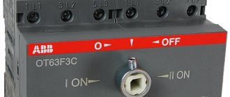
The 3-position switch has a handle with three positions for opening and closing the chain. The middle position ensures the opening of each existing group of contacts. The user controls the device manually. The upper contacts are usually used to connect inputs, and the lower ones - loads. Such a device is not equipped with releases (thermal or electromagnetic), so when installing it, automatic switches are installed at the inputs that are triggered when overloaded.
This configuration will prevent sparking incidents and damage to the integrity of the wiring insulation material. In the past, these devices were used as master input devices in switchboards. Over time, this place was taken by automatic switches, but the flexibility and simplicity of the design of position switches, as well as their low price, ensure that these products are quite popular.
Household use
Three-position switch EKF Basic
There are many options for using three-position switches for 220V in industry and everyday life:
- control of light and transformer substations;
- switching programs for the operation of electric welding, heating and other production equipment;
- manipulations with electric motor modes;
- remote control of asynchronous electric motors;
- automatic entry of reserve;
- switching in panel devices.
These products are also used for power supply to substations, for example, in grounding structures and switching measuring instruments.
Types of three-position switches
Electrical switches with 3 positions are available in various designs. Some models are equipped with the option of fixing the switch position. They are equipped with a key locking mechanism that prevents spontaneous transition to another position. Others that do not have this function return to their original position on their own. The design of some devices provides for a zero position - it involves disconnecting all contacts.
Typically, products are manufactured with the expectation of operation in electrical networks with a nominal current of 25, 16 or 10 A. As for voltage, for direct current its value can reach 220 V, for alternating current - up to 500. The devices are equipped with markings indicating the power level and protection category.
The most common design option is a 3-position mechanical packet switch. Their control element is not a button, but a handle. Modern models are equipped with ergonomic handles, the design of which prevents fingers from slipping. There are two types of products - biscuits and cams. The biscuit switch device includes plastic plates (bags) with contact pins rigidly fixed to them. Between the latter there are fiber washers for extinguishing sparks, which, together with a double break in the electric arc, make it possible to switch high currents. There is also a moving contact connected to the switching mechanism. Its position is set by turning the shaft, which is provided by a handle and a special spring, which allows you to instantly open and close the contacts. The shaft has 3 set positions, each of which corresponds to a certain configuration of clamped or open pairs of contacts. Such a device can be used, among other things, to connect a three-phase electric motor with a reverse option - rotation of the rotor in a direction other than normal.
We recommend reading: DIY FM antenna for a music center
The cam device also includes a series of packages, but arranged differently. On the outer sides of the plates connecting to the body there are moving contacts, and on the inner sides there are static ones. The first of them look like bridges with springs. Their position is regulated by a rod mechanism that changes position under the action of a cam. The latter, in turn, changes its position through the handle and shaft. Both in the case of biscuit models, and in devices with cams, the shaft can have a different number of positions (up to eight). In three-position devices their number is three.
The switch can be mounted on a DIN rail, on a wall, or in a cabinet, depending on the model. Explosion-proof products are produced for use in industries that pose a danger to human health. Most three-position switches, however, are susceptible to explosions, temperature changes, and do not tolerate moisture. The degree of sensitivity of the device to environmental conditions can be determined by its appearance: if the product is open and lacks a protective casing, it is highly sensitive; it should only be installed inside a switchboard in a room with dry air. Switches with a plastic or metal housing and contact-protected clamps can also be installed outside the switchboard.
If the housing is hermetically sealed, the device can be installed even outdoors. During operation, mild mechanical impacts and vibration are allowed (no more than 35 Hz).
The advantages of the devices include reliable operation, resistance to wear and tear, and a fairly low price. They suppress electrical arcs very quickly, but can withstand a limited number of switching overloads. A weakness of these products compared to circuit breakers is also their limited capabilities as a protective device: they do not protect against short-circuit incidents. Also, mechanical switches cannot be repaired: if the product becomes unusable, it is dismantled and subsequently disposed of, and a new one is installed in its place. They fail relatively quickly, although some manufacturers claim that the device can withstand up to half a million switchings.
Features of using a three-position switch
Three-position changeover switch
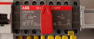
A three-pole switch is suitable for connecting backup power to a home line. It is used only after the load has been disconnected. The generator will need to be activated and set to working position. Then you need to connect your home network to it. When carrying out repair work, the switch will be used as a disconnector.
Changeover electrical equipment is installed in the switchboard. Models with a plastic case are suitable for indoor installation, and metal ones for external installation. Inside the boxes there is a special DIN rail for switches. Installation of devices is carried out as follows:
- Models that switch off under load are installed vertically.
- The type of tires and wires is selected. Their cross section must correspond to the current rating of the switches.
- Buses and wires are connected to fixed contacts.
- The elements are tightly clamped with terminals to ensure reliable contacts and eliminate the possibility of overheating.
- The threads of the nuts are coated with Vaseline.
- Contact nuts tighten smoothly. After the first turn of the wrench, the nut is loosened and then carefully tightened.
- Castor oil is applied to the surface of the contact knives, which will prevent them from jamming in the racks.
- Metal non-current-carrying elements are grounded on the outer part of the box.
Before connecting, you must stop the input machine
Three-position or package devices are produced without a disconnector. They connect like this:
- Stopping the introductory machine.
- Installing the device handle on the generator line.
- Switching off the load breaker.
- Connecting the switch cable to the generator socket.
- Start the generator, wait for warm-up (2 minutes).
- Supplying power to the switch.
- Turning on the load breakers.
Machines are installed on each of the inputs.
What is a rocker switch
Reversing changeover switch
The purpose of a changeover switch is to transfer voltage between two lines or connect several networks. Using a switch, you can eliminate current leaks during accidents and quickly switch to the entire line. The device is switched using a lever on the front panel, which is moved to 1-2 positions.
The equipment is installed in the switchboard room or near the input panel.
Device specifics
A toggle-type switch is similar to a two-position switch in its operating principle, but is distinguished by increased power and a smooth blade drive. The second difference is the switching process with a line break and operation in three positions:
- apartment/home network;
- shutdown;
- power supply from the generator.
How to connect a three-key switch with your own hands
Connecting a three-circuit device is extremely simple. To do this correctly, you need to follow many step-by-step steps. The entire connection process is divided into stages:
- connecting the cable to the three-key player;
- connection of wires in the box;
- checking the correct connection and eliminating errors.
Before carrying out the process, it is advisable to study the connection diagram. This measure will help minimize possible mistakes.
Triple switch connection diagram
There are several conductors in the box. Each performs its own function:
- The cable with 3 cores is located in the circuit breaker present in the switchboard.
- A four-wire wire runs down to a three-key switch connected to the bottom.
- The connection diagram for a triple switch for 3 lamps involves connection with a 4- or 5-core VVGnG-Ls wire. Its cross section is 1.5–2 mm. A chandelier with 6 or 9 bulbs requires the same connection.
- With 3 different lamps, you need to pull 3 different three-core cables. This method is common.
Now the number of requests for “triple switch with socket diagram” on the network has increased. It is easy to find detailed connection algorithms with photographs or drawings there.
Connecting wires to the switch
Often the device is installed in a block with an outlet. People are wondering how to connect a three-key switch. You need to take several sequential steps:
- You will need a copper wire with a cross section of 2.5 mm². Direct the cable from the common shield. When it goes from the box to the switch, it is an error.
- Run copper wire 5*2.5 mm² down the groove. Then it will be near the switch and socket box. Connect the common wire to the contact. This is due to the more powerful load on the sockets. It is not so pronounced on lamps.
- Using a jumper, connect the phase to the upper terminal of the device. Direct the zero to contact 2. Place the remaining conductors under the lower contacts.
Basic connection diagrams
The connection diagram of the changeover switch is determined by the type of electrical network.
Single-phase network
Only two-pole modifications with power supplies with an operating voltage of 300 V are connected to this line. The connection is made with a negative resistance rating of 50 Ohms. The devices are placed on copper jumpers. Installation in a residential building is carried out in electrical panels of type KK220.
Two-phase line
For a two-phase network, only expansion switches are suitable. To them you will need to add a connecting node - 220 V power supplies. The maximum voltage of modular devices is 300 V, but the presence of two modules allows an output voltage limit of 350 V.
The process of connecting switches has several nuances:
- the blocker is installed in the electrical panel together with the thyristor unit;
- the negative resistance rating is 40 ohms;
- contact systems are used only in closed switches;
- If you have two reversing units from different manufacturers, you will need a controller.
Three-phase power supply
Connection diagram of a switch to a three-phase network
The switch is combined with a power supply with an operating voltage rating of 400 V and pulse transformers. The device can be entered through the inverting output. Output currents will be supplied through pass capacitors.
For a three-phase network, it is allowed to use two-module and single-module devices. The latter must have a threshold voltage of 350 V and a negative resistance of 55 Ohms.
Changeover switches - lighting control circuit from 3 places
But what if you want to control one lighting from three or more points. That is, there will be 3, 4, etc. switches in the circuit. It would seem that you need to take another pass-through switch and that’s it.
However, a switch with three terminals will no longer work here. Since there will be four connected wires in the junction box.
Here a changeover switch, or as it is also called a cross, cross, or intermediate switch, will come to your aid. Its key difference is that it has four outlets - two at the bottom and two at the top.
And it is installed precisely in the gap between two passageways. Find in the junction box two secondary (not main) wires from the first and second pass-through switch.
You disconnect them and connect a changeover between them. Connect the wires that come from the first to the input (follow the arrows), and those that go to the second to the output terminals.
Always check the diagram on the switches! It often happens that their entrance and exit are on the same side (top and bottom). For example, the connection diagram for a Legrand Valena changeover switch:
Naturally, there is no need to stuff the changeover itself into the junction box. It is enough to lead the ends of a 4-core cable from it there. Meanwhile, you place the switch itself in any convenient place - near the bed, in the middle of a long corridor, etc. You can turn the light on and off from anywhere.
We recommend reading: Total power of a transformer: what is it, what parts does it consist of, calculation method
The most important advantage of this circuit is that it can be changed indefinitely and add as many changeover switches as you like. That is, there will always be two passing ones (at the beginning and the end), and in the interval between them there will be 4, 5 or at least 10 crossover ones.
Connection errors
Many people make a mistake at the stage of searching and connecting the common terminal in the pass-through switch. Without checking the circuit, they naively believe that the common terminal is the one with only one contact.
They assemble a circuit in this way, and then for some reason the switches do not work correctly (they depend on each other).
Remember that on different switches the common contact can be anywhere!
And it is best to call it, what is called “live”, with a tester or an indicator screwdriver.
Most often, this problem is encountered when installing or replacing pass-through switches from different companies. If everything worked before, but after replacing one circuit the circuit stopped working, it means the wires were mixed up.
But there may also be an option that the new switch is not pass-through at all. Also remember that the lighting inside the product cannot in any way affect the switching principle itself.
Another common mistake is connecting the crossovers incorrectly. When both wires are placed from pass-through No. 1 to the upper contacts, and from No. 2 to the lower ones. Meanwhile, the cross switch has a completely different circuit and switching mechanism. And you need to connect the wires crosswise.
Connection diagram
Typical connection diagrams
When purchasing cables for mounting a three-position device, it is necessary to take into account the maximum operating current values in the electrical circuit. If the diameter of the conductors exceeds 6 mm2, special tips are purchased for them. Less thick wires can be connected directly to the device using soldering or ring cutting.
Typical diagrams suitable for a particular device, including a diagram for connecting a switch from three different places, are given in the technical documentation accompanying it. Some of the three-position products can be connected not only to 3 poles, but also to 1, 2 or 4 (the possible number of poles is indicated in the device passport). At the entrance to the apartment, the device is placed at the point of tapping from the common phase conductor and zero in order to separate the apartment line from the main line. Installation of the switch and its subsequent adjustment can only be done when the electricity is turned off. Modern products designed for use in residential panels usually require installation on a 35 mm DIN rail. Their terminal clamps are marked with numbers, which avoids confusion during the installation process. After installation, the device, as well as adjacent contact connections, must be cleaned with a dry cloth at least once every 6 months, having first disconnected the power from the network.
Flaws
1The first of the disadvantages of pass-through switches is the lack of a specific ON/OFF key position, which is found in conventional ones.
If your light bulb burns out and needs to be replaced, with such a scheme it is not immediately possible to understand whether the light is on or off.
It will be unpleasant when, when replacing, the lamp may simply explode in front of your eyes. In this case, the easiest and most reliable way is to turn off the automatic lighting in the panel.
2The second disadvantage is the large number of connections in junction boxes.
And the more light points you have, the greater the number of them will be in the distribution boxes. Connecting the cable directly according to diagrams without junction boxes reduces the number of connections, but can significantly increase either the cable consumption or the number of its cores.
If your wiring goes under the ceiling, you will have to lower the wire from there to each switch, and then lift it back up. The best option here is to use pulse relays.
And if you don’t want to lay wires and ditch walls at all, is it possible to install pass-through switches in this case? It’s possible, but all costs will be around 800-1000 rubles. How to do this, read the article “Wireless pass-through switch.”
Connection diagram
After purchasing, you may have difficulty with how to connect the phase switch. If you do not have experience working with electricity, it is better not to try, since you will have to work with high voltage in a three-phase network - 380 Volts. In addition, improper use and connection of such equipment can lead to a short circuit between phases.
The phase switch is a modular device that is installed in a panel on site on a DIN rail. A three-phase circuit breaker is installed in front of it. After installing the primary circuit, we move on to the output circuit. But how to connect the secondary circuits depends on the switch model. The connection diagram must be indicated in the technical data sheet or other similar documentation and may differ from manufacturer to manufacturer.
Finally, we recommend watching a video that explains in more detail what a phase switch is and how to connect it in the panel:
A phase switch is a low-cost method that will increase the stability of the power supply; this can be especially important outside the city in a cottage or holiday village, where there are usually power outages. We talked about how to connect and where to install, as well as all the parameters of such devices. The choice of uninterrupted supply is yours based on your needs and budget.
It will be useful to read:
- How to choose a UPS for your home
- What is a phase control relay
- What is a cam switch used for?
Main advantages
Electric switch
It is impossible to distinguish the devices by appearance, but the operating principle is different. In some rooms it is inconvenient to use the switch (for example, in long corridors). The main advantages of switches are:
- the ability to connect several electrical networks to each other;
- the device allows you to control (turn on, switch, turn off) a branched electrical circuit from one point;
- one light source can be activated from different places in the room (for example, turn on the chandelier in the guest room from the corridor).
In fact, the device is constantly in working condition - this is one of the main differences between a switch and a switch. With the help of changeover contacts, additional electrical circuits are created in the network.
Electric switches work as follows. The meaning of their work is to transfer the main contact from one circuit to another. Most often, on the back of the switch housing there is a diagram of the wire connections.
One contact is common (1), the other two contacts are changeover (2 and 3). By using two of these switches and placing them in different places, you can implement the most popular and simple lighting control scheme from two different places.
Terminals 2 and 3 matching the designations with switches PV-1 and PV-2 are connected by conductors to each other. Input 1 from PV-1 is connected to the phase, and PV-2 is connected to the lighting fixtures. The other end of the lamp is connected to the neutral conductor of the network.
The functionality of the circuit is checked by turning on the switch. First, voltage is applied, and the lamp alternately lights up and goes out from the individual action of any of the switches. When the circuit of one of the switches is opened, the other line of the circuit is switched on.
Types and design features
To select the correct switch, it is necessary to determine the type of control movement of the handle, the tasks being solved, the connection diagram, and the properties of the connected circuits.
Changeover switches
Changeover switch 4-pole 63A AvaTar
An electric switch ensures disconnection of the network from one energy source and connection to another. The presence of a midpoint explains the name “cross over”. The devices are produced with arc extinguishers that provide switching when the voltage is connected. Models without arc extinguishing mechanisms are switched when the load is turned off. The switch operates only in manual mode - switching is carried out using an isolated control lever.
The design of the device is presented:
- sealed housing;
- movable blade contacts with two working positions and one intermediate;
- arc extinguishing chamber, but there are switches without it;
- terminals for connecting to the network.
Connection to one load line is carried out according to the principle:
- The main power supply is connected to contact No. 1.
- A diesel or electric generator is connected to pin No. 2.
If input into a building with three-phase voltage is required, a three-phase switch with 4 poles is used. The device is connected like this:
- You need to enter the power supply through 4 terminals.
- A generator is connected to 4 terminals.
- The load is connected to 4 terminals.
Lighting control circuit with conventional pass-through switches from two places: briefly
I present it because it simplifies the understanding of the principles inherent in the connection diagrams of two-key modules created to control light from different points.
For example, when entering the apartment corridor from the street in the evening, it is convenient to turn on the light with switch No. 1, hang your outerwear in the wall closet, go into the bedroom and turn off the unnecessary corridor lighting.
The electrical diagram for connecting wires between the lamp, distribution box, switches No. 1 and No. 2 for this case is shown below.
The zero potential in it is directly supplied to the base of the light bulb. The phase, through the switching points of the junction box, is supplied to the input terminal L1 of the first switch, and from L1 of the second switch it is sent directly to the central contact of the luminaire.
Intermediate contacts “1” and “2” of both housings are connected to each other. As a result, it turns out that the phase potential will come to the light bulb and light its filament when both pass-through keys occupy the same position (1 or 2).
When the key combination is different, the glow stops.
By placing pass-through modules No. 1 and No. 2 in different remote areas of the apartment, it is possible to switch the lamp from the part of the room where a person is located.
Longer distances will require an increased cable length. This can seriously affect the final price of the lighting system.
Educational program: a simple diagram for connecting a pass-through switch for a large number of lamps - what dangers lurk
Here I show a principle that allows you to control a different number of light sources using two pass-through modules.
For safety reasons, this structure must be powered through an isolation transformer TP1 with the secondary winding potentials isolated from the ground circuit. It is advisable to use its output circuits at a safe voltage of 12 or 24 volts.
In this wiring, to interrupt the glow of lamps, the principle is not of a phase break, as usual, but of supplying the filaments on both sides with the same phase or zero potentials, eliminating the flow of current (the appearance of voltage).
If you use this development without an isolation transformer, then you must take into account that in any position of the keys on the lamps there will always be a phase present on some side. When replacing a burnt out light bulb, there is a high risk of electric shock.
All the lamps here are assembled in a parallel chain. Their number is limited only by the conductive properties of electrical wiring and the breaking power of contact groups of switching devices.
Due to the increased risk of a person being exposed to current, this scheme is not popular in practice because rarely anyone decides to install an isolation transformer. It is usually considered as a theoretical example.
We recommend reading: LM358 microcircuit: datasheet in Russian, application, analogues, pin assignments
If you come across a proposal for its installation, then think carefully about implementing safety principles. I do not recommend it, but only included it for the purpose of increasing your knowledge.
Multi-pole switches
High pole count switches are not very common, but are available in many amazing configurations. They are described similarly to single-pole or double-pole switches/circuit switches, with the first letter (S or D) replaced by a numerical designation. This is how you can imagine, for example, a 4PDT switch that can control four separate circuits with two positions per circuit. An example of such a switch along with the circuit is shown in the figure below.
The situation is similar with switches with a large number of positions. If a four-way switch can be set to one of four positions, for example, it will be designated 4P4T. What will the SP12T switch look like? This could be a rotary switch (bar type), which has 1 pole and 12 positions.
What to replace it with?
If the packet switch (switch) fails, it must be replaced with a new device of the same type with similar (or higher) parameters. To replace the switch, you can use a circuit breaker that is designed to operate with currents and rated voltages corresponding to the loads of a given circuit. Of course, the number of poles must be respected.
For orientation on the parameters, we provide a table with the parameters.
Table 2.
| Name | Number of poles | Rated current A | Number of switchings | Degree of protection | |
| 220V | 380V | ||||
| PV1-16-M3 | 1 | 16 | 10 | 1 | IP00 |
| PV2-16-M3 | 2 | 16 | 10 | 1 | IP00 |
| PV3-16-M3 | 3 | 16 | 10 | 1 | IP00 |
| PV2-40-M3 | 2 | 40 | 25 | 1 | IP00 |
| PV3-40-M3 | 3 | 40 | 25 | 1 | IP00 |
| PV4-40-M3 | 4 | 40 | 25 | 1 | IP00 |
| PV2-100-M3 | 2 | 100 | 60 | 1 | IP00 |
| PV3-100-M3 | 3 | 100 | 60 | 1 | IP00 |
| PV4-100-M3 | 4 | 100 | 60 | 1 | IP00 |
| PV1-16-M1 IP56 plastic | 1 | 16 | 10 | 1 | IP56 |
| PV2-16-M1 IP56 plastic | 2 | 16 | 10 | 1 | IP56 |
| PV3-16-M1 IP56 plastic | 3 | 16 | 10 | 1 | IP56 |
| PV2-40-M1 IP56 plastic | 2 | 40 | 25 | 1 | IP56 |
| PV3-40-M1 IP56 plastic | 3 | 40 | 25 | 1 | IP56 |
| PV4-40-M1 IP56 plastic | 4 | 40 | 25 | 1 | IP56 |
| PV2-100-M1 IP56 plastic | 2 | 100 | 60 | 1 | IP56 |
| PV3-100-M1 IP56 plastic | 3 | 100 | 60 | 1 | IP56 |
| PV4-100-M1 IP56 plastic | 4 | 100 | 60 | 1 | IP56 |
| PP1-16-H2-M3 | 1 | 16 | 10 | 2 | IP00 |
| PP2-16-H2-M3 | 2 | 16 | 10 | 2 | IP00 |
| PP3-16-H2-M3 | 3 | 16 | 10 | 2 | IP00 |
| PP4-16-H2-M3 | 4 | 16 | 10 | 2 | IP00 |
| PP2-40-H2-M3 | 2 | 40 | 25 | 2 | IP00 |
| PP3-40-H2-M3 | 3 | 40 | 25 | 2 | IP00 |
| PP4-40-H2-M3 | 4 | 40 | 25 | 2 | IP00 |
| PP2-100-H2-M3 | 2 | 100 | 60 | 2 | IP00 |
| PP3-100-H2-M3 | 3 | 100 | 60 | 2 | IP00 |
| PP4-100-H2-M3 | 4 | 100 | 60 | 2 | IP00 |
| PP2-16-H2-M2 IP56 plastic | 2 | 16 | 10 | 2 | IP56 |
| PP3-16-H2-M2 IP56 plastic | 3 | 16 | 10 | 2 | IP56 |
| PP4-16-H2-M2 IP56 plastic | 4 | 16 | 10 | 2 | IP56 |
| PP2-40-H2-M2 IP56 plastic | 2 | 40 | 25 | 2 | IP56 |
| PP3-40-H2-M2 IP56 plastic | 3 | 40 | 25 | 2 | IP56 |
| PP4-40-H2-M2 IP56 plastic | 4 | 40 | 25 | 2 | IP56 |
| PP2-100-H2-M2 IP56 plastic | 2 | 100 | 60 | 2 | IP56 |
| PP3-100-H2-M2 IP56 plastic | 3 | 100 | 60 | 2 | IP56 |
| PP3-16-H3-M3 | 3 | 16 | 10 | 3 | IP00 |
| PP3-40-H3-M3 | 3 | 40 | 25 | 3 | IP00 |
| PP4-40-H3-M3 | 4 | 40 | 25 | 3 | IP00 |
| PP2-100-H3-M3 | 2 | 100 | 60 | 3 | IP00 |
| PP3-100-H3-M3 | 3 | 100 | 60 | 3 | IP00 |
| PP4-100-H3-M3 | 4 | 100 | 60 | 3 | IP00 |
| PP2-16-H3-M2 IP56 plastic | 2 | 16 | 10 | 3 | IP56 |
| PP3-16-H3-M2 IP56 plastic | 3 | 16 | 10 | 3 | IP56 |
| PP4-16-H3-M2 IP56 plastic | 4 | 16 | 10 | 3 | IP56 |
| PP2-40-H3-M2 IP56 plastic | 2 | 40 | 25 | 3 | IP56 |
| PP3-40-H3-M2 IP56 plastic | 3 | 40 | 25 | 3 | IP56 |
| PP4-40-H3-M2 IP56 plastic | 4 | 40 | 25 | 3 | IP56 |
| PP2-100-H3-M2 IP56 plastic | 2 | 100 | 60 | 3 | IP56 |
| PP3-100-H3-M2 IP56 plastic | 3 | 100 | 60 | 3 | IP56 |
| PP1-16-H4-M3 | 1 | 16 | 10 | 4 | IP00 |
| PP2-16-H4-M3 | 2 | 16 | 10 | 4 | IP00 |
| PP3-16-H4-M3 | 3 | 16 | 10 | 4 | IP00 |
| PP4-16-H4-M3 | 4 | 16 | 10 | 4 | IP00 |
| PP2-40-H4-M3 | 2 | 40 | 25 | 4 | IP00 |
| PP3-40-H4-M3 | 3 | 40 | 25 | 4 | IP00 |
| PP4-40-H4-M3 | 4 | 40 | 25 | 4 | IP00 |
| PP2-100-H4-M3 | 2 | 100 | 60 | 4 | IP00 |
| PP3-100-H4-M3 | 3 | 100 | 60 | 4 | IP00 |
| PP4-100-H4-M3 | 4 | 100 | 60 | 4 | IP00 |
| PP2-16-H4-M2 IP56 plastic | 2 | 16 | 10 | 4 | IP56 |
| PP3-16-H4-M2 IP56 plastic | 3 | 16 | 10 | 4 | IP56 |
| PP4-16-H4-M2 IP56 plastic | 4 | 16 | 10 | 4 | IP56 |
| PP2-40-H4-M2 IP56 plastic | 2 | 40 | 25 | 4 | IP56 |
| PP3-40-H4-M2 IP56 plastic | 3 | 40 | 25 | 4 | IP56 |
| PP4-40-H4-M2 IP56 plastic | 4 | 40 | 25 | 4 | IP56 |
| PP2-100-H4-M2 IP56 plastic | 2 | 100 | 60 | 4 | IP56 |
| PP3-100-H4-M2 IP56 plastic | 3 | 100 | 60 | 4 | IP56 |
| PP3-16-P-M3 | 3 | 16 | 10 | Reversible | IP00 |
| PP3-40-P-M3 | 3 | 40 | 25 | Reversible | IP00 |
| PP3-100-P-M3 | 3 | 100 | 60 | Reversible | IP00 |
| PP3-16-P-M2 IP56 plastic | 3 | 16 | 10 | Reversible | IP56 |
| PP3-40-P-M2 IP56 plastic | 3 | 16 | 10 | Reversible | IP56 |
| PP3-100-P-M2 IP56 plastic | 3 | 100 | 60 | Reversible | IP56 |
Installation and mechanical parameters
The switch can be integrated into the circuit in different ways. The main division in this regard is between panel-mounted and PCB-mounted elements. This is not a strict classification, as there are many switches soldered to printed circuit boards, but intended for panel applications.
Like most electronic components, they can be classified into surface mount components (SMD) or through-hole mount components (THT). Elements for through-hole assembly are usually larger, THT allows higher mechanical loads to be transferred. SMD switches are smaller than their THT counterparts, typically much lower in height, take up less PCB space, and require little force to switch.
Panel-mounted switches are equipped with elements that allow them to be mounted in a housing. They usually have threaded bodies that allow them to be tightened with a nut, but manufacturers also use other solutions. Pins are adapted for THT, SMD or cable assembly.
Environmental resistance
Panel switches are often exposed to the elements. The main threats to these elements are dust and moisture. The IP rating assigned to a switch indicates its resistance to these factors. The degree of protection and IP classes are defined in the IEC 60529 standard.
The IP class is described by two numbers, written in the IPxy format, where x is the first characteristic digit, indicating protection against access to the inside of the housing, as well as protection against dust penetration inside. And y is the second characteristic digit indicating the waterproofness of the switch.
The lowest protection class, IP00, means a device without access protection, in this case a button. The protection class indicates, for example, the size of bodies that can get inside the button, or protection against dust. In the case of protection against ingress of water, the levels of protection vary from droplets of water (level 1) to protection against flooding by a powerful jet of pressurized water (100 bar at 80°C). in accordance with DIN 40050 (class 9). The highest protection class is IP69.
Just as the IP class determines resistance to dust and moisture, the IK class determines the resistance of elements to mechanical damage, the so-called vandal resistance. The IEC 62262 standard defines the mechanical resistance of elements as the amount of mechanical shock energy that a given element can withstand without damage. The standard also specifies the height from which an element can fall without damage or other mechanical testing. The division is divided into classes from IK00 - the element is not at all resistant to mechanical damage, to IK10, where the element can withstand an impact with an energy of up to 20 J (a steel ball weighing 5 kg and with a radius of 50 mm, falling from a height of 40 cm).
Arduino button
A button (or push-button switch) is the simplest and most accessible of all types of sensors. By clicking on it, you send a signal to the controller, which then leads to some actions: LEDs turn on, sounds are made, motors start. In our lives, we often come across different switches and are very familiar with this device.
Tact buttons and switch buttons
As usual, we start the section with simple things that are interesting only to beginners. If you know the basics and want to learn about the various options for connecting a button to an Arduino, you can skip this paragraph.
What is a button? In essence, this is a fairly simple device that closes and opens the electrical network. You can perform this closing/opening in different modes, while fixing or not fixing your position. Accordingly, all buttons can be divided into two large groups:
- Switch buttons with fixation. They return to their original state after being released. When, depending on the initial state, they are divided into normally closed and normally open buttons.
- Momentary buttons (tact buttons). They are fixed and remain in the position in which they were left.
There are a lot of options for different buttons, this is truly one of the most common types of electronic components.
Arduino buttons for simple projects
In our projects we will be working with very simple 4-leg clock buttons that come with almost any Arduino kit. The button is a switch with two pairs of contacts. The contacts in one pair are connected to each other, so it will not be possible to implement more than one switch in the circuit, but you can simultaneously control two parallel segments, this can be useful.
Depending on the situation, you can create both circuits with normally closed and normally open contacts - all you need to do is make the connections in the circuit accordingly.
For ease of use, the tact button usually comes with a plastic cap of some color; it fits over the button quite obviously and gives the project a less hacker-like look.
Application area
Let us repeat that before ordering a switch, you should know that it requires 3 phases to operate. Reserve lines are taken from additional phases. Between phases the voltage is 380 Volts, it is called “linear”, and between phase and zero 220 Volts, it is called “phase”. They are related, but within the scope of this article we will not delve into the basics of electrical engineering. The main thing is for you to understand that to connect to electrical networks you need a three-phase network of 380 Volts.
As already mentioned, this device is used to connect a backup line. This only works if one of the transformer phases is overloaded or a imbalance has occurred. In cases where a “bad” voltage is supplied to the input transformer, automatic input of a reserve is required from another line; a phase switch will not help in this situation.
Units with continuous operation are powered from a phase switch. I propose to consider the scope of application in illustrative examples.
In medicine:
- life support devices;
- refrigerators with medicines in pharmacies;
In production and in offices:
- automation tools;
- control and monitoring equipment, recording signals;
- communications equipment, stationary radio stations, dispatch equipment;
- ventilation systems;
In the house:
- a gas boiler;
- security system;
- CCTV;
- “smart home” system;