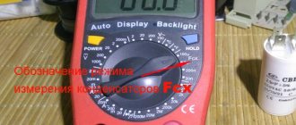
A combined group of batteries is called a battery of cells or simply a galvanic battery. There are two main ways to connect cells into batteries: series and parallel connections.
In this article, we will consider the features of serial and parallel connection of batteries. There are various situations where it may be necessary to increase the total capacity or increase the voltage by resorting to parallel or series connection of several batteries into a battery, and you always need to remember the nuances.
A parallel connection involves combining the positive battery terminals with a common positive point of the circuit, and all negative terminals with a common minus point, i.e., connect all positive terminals of the elements to one common wire, and all negative terminals to another common wire. The ends of the common wires of such a battery are connected to an external circuit - to the receiver.
The essence of the sequential method of connecting batteries, as follows from its very name, is that all the elements taken are connected to each other in one serial chain, that is, the positive pole of each element is connected to the negative pole of each subsequent element.
As a result of this connection, one common battery is obtained, in which the negative terminals of one extreme element remain free, and the positive terminals of the second element remain free. With their help, the battery is connected to an external circuit - to the receiver. Let's talk about this in more detail later.
Parallel connection of batteries results in a combination of capacities, and with an equal initial voltage on each of the batteries included in the battery assembled from them, the capacity of the composite battery turns out to be equal to the sum of the capacities of these batteries. If the capacities of the batteries being combined are equal, to find the battery capacity it is enough to multiply the number of batteries composing the battery by the capacity of one battery in the assembly.
No matter how many elements we connect in parallel, their total voltage will always be equal to the voltage of one element, but the strength of the discharge current can be increased as many times as there are elements in the battery, if only all the elements in the battery are of the same type.
By connecting the batteries in series, you get a battery with the same capacity as the capacity of one of the batteries included in the battery, provided that the capacities are equal. In this case, the battery voltage will be equal to the sum of the voltages of each of the batteries that make up the battery.
If batteries of equal capacity and equal voltage at the time of connection are connected in series, then the voltage of the battery obtained by series connection will be equal to the product of the voltage of one battery and the number of batteries making up the series circuit.
When connecting elements in series, the values of their internal resistances are also added up. Therefore, from a assembled battery, regardless of its voltage, it is possible to consume only the same amount of current as one element included in the battery is designed for. This is understandable, since with a series connection, the same current passes through each element as passes through the entire battery.
Thus, by connecting elements in series, increasing their total number, it is possible to increase the battery voltage to any limits, but the strength of the discharge current of the battery will remain the same as that of one individual element included in its composition.
With both parallel and series connections, the total energy of the battery is equal to the sum of the energies of all the batteries that make up the battery.
So, why are batteries combined into batteries? The thing is that in any circuit there are losses associated with heating of the conductors. And with the same conductor resistance, if it is necessary to transmit a certain power, it is much more profitable to transmit power at a high voltage, then less current will be required, and ohmic losses will be less.
For this reason, high-power uninterruptible power supplies use series-connected batteries with a total voltage of several tens of volts, rather than a parallel circuit of 12 volts. The higher the source voltage, the higher the efficiency of the converter.
When significant current is needed, and one available battery is not enough for the intended purpose, the battery capacity is increased by resorting to parallel connection of several batteries.
It is not always economically profitable to replace a battery with a new one with a larger capacity, and sometimes it is enough to connect another one in parallel and increase the source capacity to the required one. Some uninterruptible power supplies have compartments for installing additional batteries in parallel with the existing one, in order to increase the energy resource of the converter.
What should be considered when combining batteries in a series circuit? Batteries of different capacities (manufactured using the same technology, for example lead-acid) differ in internal resistance. The higher the capacitance, the lower the internal resistance; the relationship here is almost inversely proportional.
For this reason, if you connect batteries of different capacities in series and close the load circuit or the charging circuit, then the current through the circuit will be the same everywhere, but the voltage drops will be different. And on some of the batteries, the voltage when charging will be much higher than the nominal value, which is dangerous, and when discharging, it will be much lower than the lower limit, which is harmful. Let's look at an example below and show what this entails.
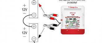
Let us have 10 batteries, the rated voltage of each is 12 volts, 9 of them have a capacity of 20 ampere-hours, and one has a capacity of 10 ampere-hours. We decided to connect them in series and charge from a charger with control of the charging current; we set the current to 2 amperes. The charger is configured to stop charging when the battery voltage crosses 138 volts, based on an average of 13.8 volts per cell in the series battery. What will happen?
For each battery, the manufacturer provides a charging characteristic, where you can see with what current and for how long the battery needs to be charged.
Obviously, a battery with 2 times smaller capacity at a current of 2 amperes will take the same amount of energy as batteries with a larger capacity, but the voltage on it will increase approximately three times faster. So, after 3 hours a small battery will take its toll, while at the same time large batteries will have to be charged for another 6 hours.
But the voltage on the small battery has already gone over the edge; it would need to be switched to voltage stabilization mode; our charger does not do this. In the end, the gas recombination system in a battery with half the capacity will not withstand it, the valves will break, and the battery will begin to lose moisture and lose capacity, while large batteries will still be undercharged.
Is this option suitable for power supplies of different capacities?
The most common are 100 A and 130 A. The reason for this limitation is that the terminals themselves will not be able to transmit such current (although theoretically the battery itself can do this). But this is the very top, which can only be a matter of seconds. Let's look at a more realistic use case.
Diagram of a device for balancing batteries
This is an analogue of a powerful zener diode loaded with a low-resistance load, the role of which here is played by diodes D2...D5. Microcircuit D1 measures the voltage at the plus and minus of the battery and if it rises above the threshold, it opens a powerful transistor, passing all the current from the charger through itself. How all this is connected together and to the power supply - see below.
The blocks turn out to be really small, and you can safely install them directly on the element. You just need to keep in mind that the potential of the negative pole of the battery arises on the transistor body, and you must be careful when installing common radiator systems - you must use insulation of the transistor bodies from each other.
Technical limitations
If you look at the technical characteristics of the permitted current value, you usually won’t see large numbers here. Thus, it is usually not allowed to connect together batteries whose capacity varies from 5 to 25 times (as a rule). Moreover, this aspect must be carefully studied, since even a short circuit is possible. The risk of its occurrence is in the range of 15-70 capacities of the smallest battery (depending on the brand and technical implementation). Roughly speaking, the less time they operate, the higher the current value you can work with. So, if the difference between them is 5 times, this means that they will be able to function all the time (theoretically). But if we are working with a 20-fold difference, then it is desirable that the count be in seconds. Many power supply manufacturers specify current thresholds for their products. For example, 2.6 A.
How, in theory, can you increase the voltage in the on-board network?
To answer this question, you need to know something about this very on-board network. How does it work, what does the voltage in it depend on? To find out, there is no need to study the entire on-board network. It is enough to consider the node that is responsible for generating electricity and stabilizing it.
The generator does this. It generates electricity to power consumers and charge batteries, and also provides stable voltage regardless of rotation speed.
In simple words, this is how it works. In order for a generator to generate electricity, an electromagnetic field is forcibly created in it. The strength of this field determines the output voltage (which goes to the battery and consumers). The electromagnetic field is created in the generator rotor, to which a constant voltage is supplied through the brush assembly. The strength of the electromagnetic field and, accordingly, the voltage of the on-board network depend on the magnitude of this voltage.
That is, in order for the network to have the required voltage, control voltage must be supplied to the brush assembly of the generator. The voltage regulator relay is responsible for this. In its simplest form, it is a device that “monitors” what the generator outputs and “decides” what control voltage to apply to excite the electromagnetic field. As a result, it turns out that no matter how fast the generator rotates, it always outputs the same voltage to the network.
Accordingly, in order to increase the voltage of the on-board network, it is necessary for the voltage regulator to supply a higher voltage to the brush assembly of the generator. This can be done in several ways, which are described below.
It is worth adding here that the on-board voltage depends not only on the generator and the relay regulator. After all, in addition to the fact that electricity must be generated, it must also be delivered to consumers, which include batteries. Accordingly, if there are losses along the delivery route, then not all generated voltage will reach consumers. Therefore, increasing the on-board voltage should start with this.
Why are there restrictions?
So, for the necessary electrochemical reaction to occur successfully, it is necessary to provide it with a high-quality electrolyte. It is also important to carry out the process in the upper layers and remove the products. The active mass of the battery plates helps with this significantly. After all, thanks to it it is easier to supply and remove the substance involved in the reaction. But as the “resource materials” move down, things start to happen more slowly. The fact that sulfur appears in the electrolyte also has an active effect. Therefore, connecting batteries in parallel is preferable only when the battery is charged. The lower the actual voltage, the more dangerous the operation of power supplies of different capacities. Therefore, it is desirable to ensure timely nutrition. It would be best not to let the capacity drop below 1/3 of the nominal value.
Features of charging in parallel connection
During the start of this process, it is preferable to transmit a fairly large charging current. After all, the surface of the battery will be restored first, and then its lower layers. At the same time, it is desirable to reduce the current, since the intensity of the electrochemical reaction decreases, as a result of which, due to the large amount of energy, the electrolyte may “boil” (its decomposition will occur).
If we consider one of the most popular types of batteries - lead-acid, then if this requirement is violated, it is unlikely to immediately fail. But its service life will obviously be significantly reduced. In general, if we talk about charging power supplies, then it is worth focusing on the fact that it is advisable to use factory devices. If you exploit something else, then certain aspects may not be taken into account (or incorrectly taken into account), which will result in problems in the future.
Method No. 2. Replacing the standard relay regulator
The average cost of a relay regulator varies around 200 rubles. This is much cheaper than a new battery, which you will have to buy due to chronic undercharging of the existing one. As a rule, these devices begin to work incorrectly over time, supplying the wrong control voltage to the generator rotor. Replacing the relay in many cases helps to increase the voltage of the on-board network to the optimal one.
It should also be taken into account that the relay regulator includes graphite brushes, through which the control voltage is transmitted to the generator rotor. And brushes tend to wear out. Therefore, in some cases, the problem with low voltage is solved by soldering new brushes to the existing relay.
About batteries and capacity
Let's consider connecting two batteries in parallel at 2 A, when they are from the same batch and are charged with a current of 2 * 2 = 4 A. There is no danger here, since due to the same design, the currents will be divided proportionally. And no lines will cross.
Now let's take power supplies, where there is a significant difference. When the current exceeds the limits set by the manufacturer, it will flow through the battery, even though it is not designed for this. We think there is no need to talk about the result. This applies to everyone, not just lead-acid batteries. Even if you want to make a parallel connection of Li-Ion batteries, which are considered to have increased reliability, do not neglect safety precautions.
Simplified diagram of a balancer for a battery
Here is a simplified circuit diagram of a current balancer based on the TL431. Resistors R1 and R2 set the voltage to 4.20 Volts, or you can choose others depending on the type of battery. The reference voltage for the regulator is removed from the transistor, and already at the border of 4.20 V, the system will begin to open the transistor slightly to prevent exceeding the specified voltage. A minimal increase in voltage will cause the transistor current to increase very quickly. During tests, already at 4.22 V (an increase of 20 mV), the current was more than 1 A.
In principle, any PNP transistor operating in the range of voltages and currents that interests us is suitable here. If the batteries are to be charged with a current of 500 mA. The calculation of its power is simple: 4.20 V x 0.5 A = 2.1 V, and this is how much the transistor must lose, which will probably require some cooling. For a charging current of 1 A or more, the power loss increases accordingly, and it will become increasingly difficult to get rid of the heat. During the test, several different transistors were tested, in particular BD244C, 2N6491 and A1535A - they all behave the same.
The voltage divider R1 and R2 should be selected so as to obtain the desired clamping voltage. For convenience, here are a few values, after applying which we will get the following results:
- R1 + R2 = Vo
- 22K + 33K = 4.166 V
- 15K + 22K = 4.204 V
- 47K + 68K = 4.227 V
- 27K + 39K = 4.230 V
- 39K + 56K = 4.241 V
- 33K + 47K = 4.255 V
We are looking for other ways to turn on batteries
We have paid considerable attention to the parallel connection of batteries. We hope that this will help solve the problems. But if, while reading the article, the thought occurred to you that the solutions described here are not suitable for any specific case, we suggest that you familiarize yourself with the following:
- Serial connection. Roughly speaking, we increase the voltage that uninterruptible power supplies will give us.
- Mixed connection. In this case, there is a simultaneous increase in both current and voltage. But this is a very difficult scheme to build.
Switching errors and their consequences
The most important thing is to avoid electric shock
. Incorrect combination of chemical current sources will entail:
- Formation of a short-circuited circuit. A chemical reaction will begin in the galvanic cells, which will lead to leakage of the electrolyte, warping of the housing, explosion, fire (typical for a parallel connection).
- Opening the circuit. When connecting a load, a reverse current will be generated through an incorrectly connected source. This will lead to rapid failure of the unit (typical for a serial connection).
- Long-term short circuit. The result is wire melting, fire, case warping, chemical reaction inside the sources, ignition, electrolyte leakage and explosion.
- Short circuit. The result is a decrease in capacity and damage to the electrodes.
- Overheating and melting of conductors. The result is a short circuit (if the conductor cross-section is incorrectly selected).
Parallel and series connection of batteries - what is it?
When connected in parallel,
the batteries are connected so that the positive terminals of all batteries are connected to one point of the electrical circuit ("plus"), and the negative terminals of all batteries are connected to another point of the circuit ("minus").
The resulting battery in parallel connection
has the same voltage as a single battery, and the capacity of such a battery is equal to the sum of the capacities of the batteries included in it. Those. if the batteries have the same capacities, then the capacity of the battery is equal to the capacity of one battery multiplied by the number of batteries in the battery.
To connect batteries in series, connect the positive terminal of the first battery to the “plus” of the electrical circuit.
battery The positive terminal of the second battery is connected to its negative terminal, etc. The negative terminal of the last battery is connected to the “minus” of the electrical circuit.
The resulting battery in series connection
has the same capacity as a single battery, and the voltage of such a battery is equal to the sum of the voltages of the batteries included in it. Those. If the batteries have the same voltage, then the battery voltage is equal to the voltage of one battery multiplied by the number of batteries in the battery.
Electrical energy stored in a battery
is equal to the sum of the energies of individual batteries (the product of the energies of individual batteries, if the batteries are the same), regardless of whether the batteries are connected in parallel or in series.
How it works
When all lithium polymer batteries are connected to the parallel charging board, they are charged evenly and fully balanced. You may be wondering how this works?
When connected in parallel, the individual batteries become one large battery. As we have already said, the moment they are connected together, a current surge occurs to equalize the voltage differences. After this, the voltages will be the same in all packages. But how do cells balance during charging?
Similar to the above, with parallel charging, the individual cells within each battery are also connected to each other by balancing terminals. For example, cell 1 in battery 1 is connected to cell 1 in battery 2. From the charger's perspective, these cells would be treated as a single LiPo battery, having its own voltage to control balance.
Why connect batteries to form a battery?
In any electrical systems or devices there are ohmic losses: part of the electrical energy is converted into heat without producing useful work. The higher the voltage of the electrical system, the lower (with the same power) the current, the lower the ohmic losses and the lower the price of the system. Those. It is beneficial to have high voltage electrical systems. Moreover, the greater the power of the system, the greater the gain of the high-voltage system compared to the low-voltage one. Therefore, small UPS (several hundred VA) usually have one 12-volt battery (this is cheaper), a UPS with a voltage of several kVA uses a battery with a voltage of tens of volts, and in powerful UPS with a voltage of tens of kilowatts, the battery voltage can exceed 500 V .
Therefore, the purpose of using rechargeable batteries
with series connection of batteries - reducing losses and increasing efficiency.
And sometimes the capacity of one battery is not enough, and you need to increase the capacity. Sometimes it is more convenient not to replace a battery with a larger capacity, but to place another one of the same battery in parallel, so that the total battery capacity of the battery doubles.
For example, to increase the operating time of a high-quality Eaton Powerware 9130 UPS from a battery, one or more of the same batteries are connected in parallel to the existing battery.
Connection Precautions
With all methods of connecting batteries, a number of precautions must be observed:
- observe safety precautions for the operation of electrical installations to prevent electric shock (the main thing is not to create a circuit for the passage of current through the human body):
- observe the polarity of the connection;
- do not create short circuits;
- when assembling batteries, disconnect the load from them;
- connect the charger to the battery when it is disconnected from the network;
- carry out work in appropriate insulating clothing and shoes, without metal objects that could fall and short circuit the contacts;
- do not touch the battery terminals with your hands, especially with both hands on different poles (this is very dangerous on powerful high-voltage batteries);
- use a special tool with insulated parts;
- do not carry out work if you are in poor health;
- take into account the currents passing through the combined battery and the load and use conductors of suitable cross-section;
- when connecting elements into one battery, ensure reliable contact isolated from external influences;
- provide reliable protection of prefabricated batteries from short circuits and moisture;
- use batteries with the same characteristics and degree of wear;
- Carefully check the assembled battery for switching errors.
Is it possible to connect lead batteries of different capacities in series?
And it is known that the internal resistance of batteries manufactured using the same technology is approximately inversely proportional to the battery capacity. Therefore, when current flows through a series battery, lead batteries of different capacities will have different voltages. Is this dangerous for individual batteries and for the battery as a whole? Let us consider separately the discharge and charging modes of lead batteries.
Suppose we are charging a series battery consisting of seven 12-volt lead-acid batteries with a capacity of 10 Ah and one 12-volt lead-acid battery with a capacity of 8 Ah. At the beginning, all batteries are discharged. The charger implements an IU charging algorithm with an initial current of 1 A and a final voltage of 110 V (13.8 V on average per battery).
According to the manufacturer, when charging batteries with direct current, the voltage on the battery
changes according to the graph on the right. At the beginning of the charging process, the charger maintains a current of 1 A, and the total voltage on the battery is the sum of the voltages on individual batteries; the voltage for each battery can be determined by its charging characteristics (a graph of battery voltage versus time, which is given by the manufacturer in its technical characteristics ). At the beginning of charging, an 8 A*h lead battery will have about 12.3 V, and all 10 A*h batteries will have about 12 V each. Starting charging is absolutely safe for all 8 batteries.
After another 3-4 hours, the voltage on the battery will reach the limit - 110 V. This voltage will be divided as follows: on batteries with a capacity of 10 A*hour it will be slightly more than 13.5 V, and on a battery with a capacity of 8 A*hour it will be more than 15 V. The recombination system of gases released in this battery will no longer cope with the load, the battery safety valves will open, the battery will begin to lose water, and with it capacity. At the same time, all batteries with a capacity of 10 Ah will be undercharged. Consequently, when charging lead batteries, batteries of different capacities connected in series will diverge more and more in their parameters - “scatter”.
Let us now consider the discharge of the same battery of 8 lead batteries with a current of 1 A. Let the system be built in such a way that when the voltage decreases to 84 V, the deep discharge protection is triggered and the discharge stops. The initial state of all lead batteries is “fully charged”. 7-8 hours after the start of discharge, a battery with a capacity of 8 A*hour will be completely discharged. The voltage on it will be 10.5 V. The voltage on the remaining batteries of the battery will be at this time a little more than 11 V each. This means that the total voltage on the battery is still far from the final discharge voltage of 84 V and is approximately 10.5 * 7 + 11.1 = 88.2 V. Therefore, the entire battery will continue to discharge, including the long-suffering battery with a capacity of 8 A*hour. The voltage on it will drop very quickly, while other lead batteries will practically not discharge. When the voltage across it reaches approximately 7 V, the system will turn off the load, but it will be too late - the battery will be in a state of deep discharge and will lose some of its capacity.
Now it becomes clear that only lead batteries of the same capacity can be connected in series, otherwise the battery will quickly fail. It is recommended to use lead batteries of the same type, same factory and from the same batch for series connection. If it is intended to combine more than two lead-acid batteries in series into a battery, it is also very desirable to pre-select the batteries by capacity and voltage using battery testers
Method number 1. Minimizing losses
On the path of electric current from the generator to consumers, the greatest losses occur in places of poor contacts. We are talking about the terminals and spots with which the wires are connected. If in such places the contact has deteriorated due to oxide or other dirt, this means that the cross-section here has decreased. And as the cross-section of the conductor decreases, its electrical resistance increases in direct proportion.
Through such contacts, the current flows “worse”; accordingly, the voltage also drops (Ohm’s law works for a section of the circuit). If, for example, on the way from the generator to the battery, all connecting contacts are in poor condition, then low voltage in the on-board network is guaranteed.
It turns out that in order to increase this very voltage, sometimes it is enough just to put at least the key connections in order. Remove oxides, rust, carbon deposits, dust, dirt. Tighten the fasteners securely. This must be done regularly, since the presence of electric current in the conductor, and moisture and salts on its surface, accelerates its corrosion.
In addition to where the conductors connect to automotive equipment, you should also be aware of the conductors themselves. They must have a cross-section sufficient for their section of the chain. Otherwise, there will also be losses on the wires, which, according to the Joule-Lenz law, will be spent on heating them.
How to reduce wire resistance? This is affected by their length and cross-section. We will not consider the material, since today all the wires are copper. If the car's wiring has been repaired and replaced, it is necessary to check whether there are any uselessly long wires that can easily be shortened. As for the cross-section, it is not always possible to judge it by its thickness. And that's why.
The fact is that the wires of the car on-board network are made multi-core. Each of them consists of many thin veins twisted into one conductor. This is done so that the wire has a larger cross-section and, at the same time, remains flexible. During long-term operation, copper strands can break, which is why the cross-section decreases, and the resistance with losses in this area increases. Most often, fractures can be seen at the ends of the conductors, where the protective insulation has been removed from them (in front of the terminals).
As practice shows, all the factors described in this subsection together are capable of reducing the on-board voltage by up to 1 volt. Accordingly, if shortcomings of this kind are eliminated, then on the voltmeter, instead of a sluggish 13.2 V, you can see the optimal 14.2 V. Such an increase will be observed if the case is completely advanced. And so, you can count on an increase in the voltage of the on-board network by several fractions of a volt (which is often not enough).
However, that's not all. In addition to the reduction in voltage, due to the problems described, it drops significantly under heavy loads. For example, when everything is turned off, the voltmeter shows 14.2 V (order). And after turning on the lights, headlights, stove and music, the readings drop to 13 V. So, quite often, after minimizing losses, such a drawdown was reduced by half, or even three.
Is it possible to connect lead batteries of different capacities in parallel?
For parallel-connected lead acid batteries, there is no danger of different voltages appearing at the battery terminals. The voltages on all parallel-connected batteries are the same due to the very nature of the connection. This means that batteries connected in parallel cannot “run apart” - they will be discharged or charged synchronously.
But lead-acid batteries have limitations not only on maximum and minimum voltage, but also on current. For example, for the CSB GP 1272 (GP1272) battery, the manufacturer has set the following current limits.
The maximum discharge current should not exceed 100 A for batteries with terminals 3/16" wide (4.75 mm) and 130 A for batteries with terminals ¼" (6.35 mm) - 130 A (18C). The flow of such a large current through a battery with a capacity of only 7.2 A*hour is also limited in time: no more than 5 s. It is clear why the discharge current is limited - the battery terminals cannot reliably transfer more current (although the battery itself probably could).
If we look at the technical characteristics of batteries from different manufacturers (although not all indicate the maximum permissible current), we will see a rather motley picture. For stationary (industrial) lead-acid batteries, the maximum current is limited to a value that numerically (in amperes) ranges from 5 to 25 battery capacities (in A*hour). Some manufacturers also indicate the short-circuit current (sometimes with a time limit of 0.1 s) - it ranges from 15 to 70 battery capacities (15C. 70C). Summarizing these data, we can say that a lead battery can be safely discharged with very high currents, up to tens of C, and the shorter the discharge time, the greater the permissible current.
The manufacturer of the CSB GP 1272 (GP1272) does not provide a strict limitation on the maximum charging current; it only recommends limiting the maximum current of the charger to 2.16 A (this is numerically equal to 30% of the battery capacity - 0.3C). This limitation is definitely not related to the capabilities of the conductors (the terminals and grid of battery plates) - the conductors of this battery, as we already know, can transmit 50 times more current. Then what is the reason for this limitation?
In the process of charging a lead battery, lead sulfate turns into lead or lead oxide (depending on whether the reaction occurs on the positive or negative plate), and the sulfur that was part of the lead sulfate goes into the electrolyte. For the electrochemical reaction of charging a lead battery to proceed effectively, it is necessary to constantly supply fresh electrolyte to the surface on which the reaction occurs and remove the reaction products (the same electrolyte, but already containing more sulfur). The active mass of the lead battery plate has a porous structure (this increases the active surface and capacity of the lead battery). It is very easy to supply (and remove) substances participating in the reaction to the open part of the active surface, and the transfer of fresh electrolyte deep into the porous plate is difficult - as you move away from the surface, the pores become narrower and deeper. Therefore, at the beginning of charging a lead battery, the electrochemical reaction occurs mainly on the open surface of the plates and only then spreads deep into the active mass. At the beginning of charging, the battery is able to safely accept a fairly large charging current - after all, as much fresh electrolyte can be quickly delivered to the surface of the plate. But as the charging process moves deeper into the active mass, the charging current must be reduced, otherwise instead of the electrochemical reaction of charging the battery, decomposition of the electrolyte will occur (the battery will “boil”). A lead battery may not fail immediately, but its aging will accelerate and it will lose capacity sooner.
Compliance with the general charger current limit (2.16 A for the CSB GP 1272 (GP1272) battery, established by the manufacturer, allows you to safely charge the battery, regardless of the depth and nature of its discharge and temperature (within limits specified by the manufacturer). However, at the beginning of charging lead battery, a higher charging current is acceptable.
Let us now return to parallel-connected lead-acid batteries. It is clear that if the total current through the parallel battery does not exceed the limits set for each battery cell, then there is no danger to the batteries. It is also clear that if we connect in parallel 5 CSB GP 1272 (GP1272) batteries from the same batch and charge them with a current of 5 x 2 = 10 A, then again there is no danger - the batteries are absolutely identical, the currents will be divided equally, and the current through each battery will not exceed the manufacturer's limit.
But if we connect different batteries into a parallel battery, and the total discharge or charging current significantly exceeds the limits set for a separate lead battery, then a current may flow through one battery that exceeds the capabilities of this battery. Let's now see how the currents are distributed between the lead batteries of a parallel battery composed of batteries of different types.
At the beginning of charging or discharging a parallel battery, the currents (charging or discharging) will be divided between the batteries in inverse proportion to their internal resistance. If lead batteries vary greatly in capacity, design, plate composition or manufacturing technology, then the internal resistance of the batteries may not be exactly inversely proportional to their capacity. In this case, the currents at the beginning of discharging or charging lead batteries may not be distributed entirely in proportion to their capacity.
Lead-acid batteries connected in parallel have the same voltage at their terminals. Therefore, their discharge or charging occurs synchronously: it is impossible for one of the parallel-connected batteries to be half discharged (or charged) and the other to be completely discharged. Therefore, some time after the start of discharging or charging, the currents begin to be redistributed between the batteries so as to compensate for the disproportion that may have occurred at the beginning of the process. Ultimately (or rather, on average), the currents are distributed among the batteries in proportion to their actual capacity, even if the internal resistance of the batteries is not exactly inversely proportional to the capacity of the batteries.
Therefore, the beginning of discharge or charging of lead batteries connected in parallel poses a potential danger. But at the beginning of discharging or charging, as we have already found out, lead batteries can be discharged or charged without harm to themselves with currents that exceed the limits set by the manufacturer. Therefore, one could say that parallel connection of dissimilar batteries does not pose any danger. But we will be more careful and say that there is almost no such danger - but when connecting lead batteries of different capacities or manufactured using different technologies in parallel, it is necessary to avoid situations where the charging or discharging current of the battery is several times higher than the limit value of the charging or discharging current set by the manufacturer one battery.
Chargers with multiple outputs
To simultaneously charge several batteries from a 220 V network, chargers with two or three outputs are used. If it is necessary to connect a larger number of battery groups, install one of the previously listed decoupling devices.
For example, to charge four batteries, you will need one charger with three outputs and one decoupling relay or charging separator.
Examples of chargers with multiple outputs:
- Ultra Light charger
- 30 Amps
- Charging profiles for Gel, AGM, liquid acid and LiFePO4 batteries. Power supply and half power mode. Login for BMS
- Two outputs Each charger output is capable of carrying maximum current. The total current does not exceed 30 A
ORDER
2 year warranty
- Ultra charger
- 60 Amps
- Marine charger. Efficiency > 90%. Three exits. 12 charging profiles. Gel, AGM, liquid-electrolyte, LiFePO4.
- Temperature sensor included The device reduces the charging voltage if the battery temperature exceeds 20 C
ORDER
5 year warranty
- PS1255 charger
- 10 Amps
- Waterproof charger. Two exits. Current 10 A
- Suitable for one or two independent or series connected batteries Charging current varies from 0 to 10 A per channel
ORDER
2 year warranty