Operating principle
A position switch allows you to control the flow of current in multiple circuits. This actuated switch gives you the option of selecting power sources or disabling them permanently. What does this mean in practice? If you switch it from one position to another, the position of the jumper will change - the current flow opens and closes, and the device is turned on, off or switched to another function. We offer a 380V three-position switch as a mechanical switching device. It is also worth mentioning that one bundle can contain many elements located in different configurations and in different chambers, so one accessory can be used to control several circuits. It sounds a little complicated, but in fact the whole design is quite simple and is found in most everyday devices, such as a car ignition switch or an electric oven that has several functions.
Lighting control circuit with conventional pass-through switches from two places: briefly
I present it because it simplifies the understanding of the principles inherent in the connection diagrams of two-key modules created to control light from different points.
For example, when entering the apartment corridor from the street in the evening, it is convenient to turn on the light with switch No. 1, hang your outerwear in the wall closet, go into the bedroom and turn off the unnecessary corridor lighting.
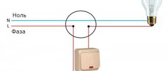
The electrical diagram for connecting wires between the lamp, distribution box, switches No. 1 and No. 2 for this case is shown below.
The zero potential in it is directly supplied to the base of the light bulb. The phase, through the switching points of the junction box, is supplied to the input terminal L1 of the first switch, and from L1 of the second switch it is sent directly to the central contact of the luminaire.
Intermediate contacts “1” and “2” of both housings are connected to each other. As a result, it turns out that the phase potential will come to the light bulb and light its filament when both pass-through keys occupy the same position (1 or 2).
When the key combination is different, the glow stops.
By placing pass-through modules No. 1 and No. 2 in different remote areas of the apartment, it is possible to switch the lamp from the part of the room where a person is located.
Longer distances will require an increased cable length. This can seriously affect the final price of the lighting system.
Educational program: a simple diagram for connecting a pass-through switch for a large number of lamps - what dangers lurk
Here I show a principle that allows you to control a different number of light sources using two pass-through modules.
For safety reasons, this structure must be powered through an isolation transformer TP1 with the secondary winding potentials isolated from the ground circuit. It is advisable to use its output circuits at a safe voltage of 12 or 24 volts.
In this wiring, to interrupt the glow of lamps, the principle is not of a phase break, as usual, but of supplying the filaments on both sides with the same phase or zero potentials, eliminating the flow of current (the appearance of voltage).
If you use this development without an isolation transformer, then you must take into account that in any position of the keys on the lamps there will always be a phase present on some side. When replacing a burnt out light bulb, there is a high risk of electric shock.
All the lamps here are assembled in a parallel chain. Their number is limited only by the conductive properties of electrical wiring and the breaking power of contact groups of switching devices.
Due to the increased risk of a person being exposed to current, this scheme is not popular in practice because rarely anyone decides to install an isolation transformer. It is usually considered as a theoretical example.
We recommend reading: LM358 microcircuit: datasheet in Russian, application, analogues, pin assignments
If you come across a proposal for its installation, then think carefully about implementing safety principles. I do not recommend it, but only included it for the purpose of increasing your knowledge.
Multi-position switches of modular type
The cam burst switch is the most common type of these devices, like other switches, it is used to control various types of electrical loads.
Cam switches
The scope of application of cam switches is quite extensive; here are some examples of their use:
- AC and DC control switchboards;
- emergency shutdown systems, automatic transfer of reserve, switching of operating modes of electric motors;
- control of transformer substations and lighting;
- equipment for substations (control of grounding switches, sectional switches, disconnectors, etc.);
- switching heating equipment modes (turning on, off, switching electric heating elements of the load);
- selection of operating mode of electric welding equipment, etc.
Cam switches consist of several packages (each responsible for switching one line) placed in one housing. The figure below shows the structure of such a package.
Cam Switch Package
Designations in the figure:
- a - fixed contacts (4 pcs.), to which wires are connected;
- b – a special protrusion “cam”, which allows you to hold and move the rod;
- c – group of movable contacts (there are two of them in this type);
- d – two guide grooves (allow the rod to make translational movements);
- e – two rods covered with an insulating shell;
- f – contacts (8 pcs.), usually made of an alloy containing silver;
- g – package;
- h – two threaded rods (fix the bag and the lid);
- I – rotor;
- J – four springs (return the rod to the closed position);
- k - shaft connecting the handle to the rotor;
- l – four screws for clamping cable wires.
Note that the batch switch (cam switch) can have several positions, including zero, that is, when the contacts are disconnected. The figure shows the state of the switch in the neutral position.
Schematic representation of the switch in the zero position
ABB switch in zero position mode
Note that all the main characteristics of the switches are indicated on the device case; the following are displayed there:
- switch type;
- rated current for which the switch is designed;
- switching diagram and table;
- protection class.
Below is a diagram and switching table shown on the housing of the SPAMEL rotation direction switch.
Scheme and switching table of the SPAMEL switch
Thanks to this table, you can clearly see in what position and which groups of contacts are connected.
Arduino button
A button (or push-button switch) is the simplest and most accessible of all types of sensors. By clicking on it, you send a signal to the controller, which then leads to some actions: LEDs turn on, sounds are made, motors start. In our lives, we often come across different switches and are very familiar with this device.
Tact buttons and switch buttons
As usual, we start the section with simple things that are interesting only to beginners. If you know the basics and want to learn about the various options for connecting a button to an Arduino, you can skip this paragraph.
What is a button? In essence, this is a fairly simple device that closes and opens the electrical network. You can perform this closing/opening in different modes, while fixing or not fixing your position. Accordingly, all buttons can be divided into two large groups:
- Switch buttons with fixation. They return to their original state after being released. When, depending on the initial state, they are divided into normally closed and normally open buttons.
- Momentary buttons (tact buttons). They are fixed and remain in the position in which they were left.
There are a lot of options for different buttons, this is truly one of the most common types of electronic components.
Arduino buttons for simple projects
In our projects we will be working with very simple 4-leg clock buttons that come with almost any Arduino kit. The button is a switch with two pairs of contacts. The contacts in one pair are connected to each other, so it will not be possible to implement more than one switch in the circuit, but you can simultaneously control two parallel segments, this can be useful.
Depending on the situation, you can create both circuits with normally closed and normally open contacts - all you need to do is make the connections in the circuit accordingly.
For ease of use, the tact button usually comes with a plastic cap of some color; it fits over the button quite obviously and gives the project a less hacker-like look.
Features of using a three-position switch
Three-position changeover switch
A three-pole switch is suitable for connecting backup power to a home line. It is used only after the load has been disconnected. The generator will need to be activated and set to working position. Then you need to connect your home network to it. When carrying out repair work, the switch will be used as a disconnector.
Device installation
Changeover electrical equipment is installed in the switchboard. Models with a plastic case are suitable for indoor installation, and metal ones for external installation. Inside the boxes there is a special DIN rail for switches. Installation of devices is carried out as follows:
- Models that switch off under load are installed vertically.
- The type of tires and wires is selected. Their cross section must correspond to the current rating of the switches.
- Buses and wires are connected to fixed contacts.
- The elements are tightly clamped with terminals to ensure reliable contacts and eliminate the possibility of overheating.
- The threads of the nuts are coated with Vaseline.
- Contact nuts tighten smoothly. After the first turn of the wrench, the nut is loosened and then carefully tightened.
- Castor oil is applied to the surface of the contact knives, which will prevent them from jamming in the racks.
- Metal non-current-carrying elements are grounded on the outer part of the box.
Switching order
Before connecting, you must stop the input machine
Three-position or package devices are produced without a disconnector. They connect like this:
- Stopping the introductory machine.
- Installing the device handle on the generator line.
- Switching off the load breaker.
- Connecting the switch cable to the generator socket.
- Start the generator, wait for warm-up (2 minutes).
- Supplying power to the switch.
- Turning on the load breakers.
Machines are installed on each of the inputs.
How to connect
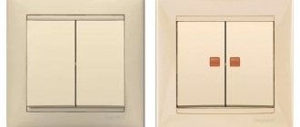
Let's give an example of implementing a lighting control scheme from two places using Legrand switches. This manufacturer produces reliable household models of the Cariva and Valena series, the price of which is not much different from the cost of conventional switches.
Before you buy switches, pay attention to the various designs; they can be for both hidden and open wiring, as well as with backlighting and position indication on the box (case). We remind you that all work related to connecting electrical equipment must be performed only when the electrical circuits are completely de-energized.
Therefore, before proceeding, make sure that the electricity is turned off; it is advisable to use a special device (probe) for this.
We remind you that all work related to connecting electrical equipment must be performed only when the electrical circuits are completely de-energized. Therefore, before proceeding, make sure that the electricity is turned off; it is advisable to use a special device (probe) for this.
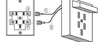
A schematic implementation of the task is shown in the figure below.
Schematic illustration of a dual lighting control installation
The neutral wire is blue, the phase is red. Note that all switching must be performed with the phase.
How a single-key switch is connected can be seen in the bottom figure.
Installation diagram of two Legrand single-key switches
Connecting switches for management from three places is as follows.
Connection to control lighting from three different locations
As you can see, it’s not difficult to connect a one-key or two-key two-way switch, and it will help make lighting control in your apartment more comfortable.
Connection diagram
Typical connection diagrams
When purchasing cables for mounting a three-position device, it is necessary to take into account the maximum operating current values in the electrical circuit. If the diameter of the conductors exceeds 6 mm2, special tips are purchased for them. Less thick wires can be connected directly to the device using soldering or ring cutting.
Typical diagrams suitable for a particular device, including a diagram for connecting a switch from three different places, are given in the technical documentation accompanying it. Some of the three-position products can be connected not only to 3 poles, but also to 1, 2 or 4 (the possible number of poles is indicated in the device passport). At the entrance to the apartment, the device is placed at the point of tapping from the common phase conductor and zero in order to separate the apartment line from the main line. Installation of the switch and its subsequent adjustment can only be done when the electricity is turned off. Modern products designed for use in residential panels usually require installation on a 35 mm DIN rail. Their terminal clamps are marked with numbers, which avoids confusion during the installation process. After installation, the device, as well as adjacent contact connections, must be cleaned with a dry cloth at least once every 6 months, having first disconnected the power from the network.
As a home network switching device, manual position switches are often considered an obsolete device. However, the ease of management and installation, as well as the price, provide them with some popularity to this day.
What to replace it with?
If the packet switch (switch) fails, it must be replaced with a new device of the same type with similar (or higher) parameters. To replace the switch, you can use a circuit breaker that is designed to operate with currents and rated voltages corresponding to the loads of a given circuit. Of course, the number of poles must be respected.
For orientation on the parameters, we provide a table with the parameters.
Table 2.
| Name | Number of poles | Rated current A | Number of switchings | Degree of protection | |
| 220V | 380V | ||||
| PV1-16-M3 | 1 | 16 | 10 | 1 | IP00 |
| PV2-16-M3 | 2 | 16 | 10 | 1 | IP00 |
| PV3-16-M3 | 3 | 16 | 10 | 1 | IP00 |
| PV2-40-M3 | 2 | 40 | 25 | 1 | IP00 |
| PV3-40-M3 | 3 | 40 | 25 | 1 | IP00 |
| PV4-40-M3 | 4 | 40 | 25 | 1 | IP00 |
| PV2-100-M3 | 2 | 100 | 60 | 1 | IP00 |
| PV3-100-M3 | 3 | 100 | 60 | 1 | IP00 |
| PV4-100-M3 | 4 | 100 | 60 | 1 | IP00 |
| PV1-16-M1 IP56 plastic | 1 | 16 | 10 | 1 | IP56 |
| PV2-16-M1 IP56 plastic | 2 | 16 | 10 | 1 | IP56 |
| PV3-16-M1 IP56 plastic | 3 | 16 | 10 | 1 | IP56 |
| PV2-40-M1 IP56 plastic | 2 | 40 | 25 | 1 | IP56 |
| PV3-40-M1 IP56 plastic | 3 | 40 | 25 | 1 | IP56 |
| PV4-40-M1 IP56 plastic | 4 | 40 | 25 | 1 | IP56 |
| PV2-100-M1 IP56 plastic | 2 | 100 | 60 | 1 | IP56 |
| PV3-100-M1 IP56 plastic | 3 | 100 | 60 | 1 | IP56 |
| PV4-100-M1 IP56 plastic | 4 | 100 | 60 | 1 | IP56 |
| PP1-16-H2-M3 | 1 | 16 | 10 | 2 | IP00 |
| PP2-16-H2-M3 | 2 | 16 | 10 | 2 | IP00 |
| PP3-16-H2-M3 | 3 | 16 | 10 | 2 | IP00 |
| PP4-16-H2-M3 | 4 | 16 | 10 | 2 | IP00 |
| PP2-40-H2-M3 | 2 | 40 | 25 | 2 | IP00 |
| PP3-40-H2-M3 | 3 | 40 | 25 | 2 | IP00 |
| PP4-40-H2-M3 | 4 | 40 | 25 | 2 | IP00 |
| PP2-100-H2-M3 | 2 | 100 | 60 | 2 | IP00 |
| PP3-100-H2-M3 | 3 | 100 | 60 | 2 | IP00 |
| PP4-100-H2-M3 | 4 | 100 | 60 | 2 | IP00 |
| PP2-16-H2-M2 IP56 plastic | 2 | 16 | 10 | 2 | IP56 |
| PP3-16-H2-M2 IP56 plastic | 3 | 16 | 10 | 2 | IP56 |
| PP4-16-H2-M2 IP56 plastic | 4 | 16 | 10 | 2 | IP56 |
| PP2-40-H2-M2 IP56 plastic | 2 | 40 | 25 | 2 | IP56 |
| PP3-40-H2-M2 IP56 plastic | 3 | 40 | 25 | 2 | IP56 |
| PP4-40-H2-M2 IP56 plastic | 4 | 40 | 25 | 2 | IP56 |
| PP2-100-H2-M2 IP56 plastic | 2 | 100 | 60 | 2 | IP56 |
| PP3-100-H2-M2 IP56 plastic | 3 | 100 | 60 | 2 | IP56 |
| PP3-16-H3-M3 | 3 | 16 | 10 | 3 | IP00 |
| PP3-40-H3-M3 | 3 | 40 | 25 | 3 | IP00 |
| PP4-40-H3-M3 | 4 | 40 | 25 | 3 | IP00 |
| PP2-100-H3-M3 | 2 | 100 | 60 | 3 | IP00 |
| PP3-100-H3-M3 | 3 | 100 | 60 | 3 | IP00 |
| PP4-100-H3-M3 | 4 | 100 | 60 | 3 | IP00 |
| PP2-16-H3-M2 IP56 plastic | 2 | 16 | 10 | 3 | IP56 |
| PP3-16-H3-M2 IP56 plastic | 3 | 16 | 10 | 3 | IP56 |
| PP4-16-H3-M2 IP56 plastic | 4 | 16 | 10 | 3 | IP56 |
| PP2-40-H3-M2 IP56 plastic | 2 | 40 | 25 | 3 | IP56 |
| PP3-40-H3-M2 IP56 plastic | 3 | 40 | 25 | 3 | IP56 |
| PP4-40-H3-M2 IP56 plastic | 4 | 40 | 25 | 3 | IP56 |
| PP2-100-H3-M2 IP56 plastic | 2 | 100 | 60 | 3 | IP56 |
| PP3-100-H3-M2 IP56 plastic | 3 | 100 | 60 | 3 | IP56 |
| PP1-16-H4-M3 | 1 | 16 | 10 | 4 | IP00 |
| PP2-16-H4-M3 | 2 | 16 | 10 | 4 | IP00 |
| PP3-16-H4-M3 | 3 | 16 | 10 | 4 | IP00 |
| PP4-16-H4-M3 | 4 | 16 | 10 | 4 | IP00 |
| PP2-40-H4-M3 | 2 | 40 | 25 | 4 | IP00 |
| PP3-40-H4-M3 | 3 | 40 | 25 | 4 | IP00 |
| PP4-40-H4-M3 | 4 | 40 | 25 | 4 | IP00 |
| PP2-100-H4-M3 | 2 | 100 | 60 | 4 | IP00 |
| PP3-100-H4-M3 | 3 | 100 | 60 | 4 | IP00 |
| PP4-100-H4-M3 | 4 | 100 | 60 | 4 | IP00 |
| PP2-16-H4-M2 IP56 plastic | 2 | 16 | 10 | 4 | IP56 |
| PP3-16-H4-M2 IP56 plastic | 3 | 16 | 10 | 4 | IP56 |
| PP4-16-H4-M2 IP56 plastic | 4 | 16 | 10 | 4 | IP56 |
| PP2-40-H4-M2 IP56 plastic | 2 | 40 | 25 | 4 | IP56 |
| PP3-40-H4-M2 IP56 plastic | 3 | 40 | 25 | 4 | IP56 |
| PP4-40-H4-M2 IP56 plastic | 4 | 40 | 25 | 4 | IP56 |
| PP2-100-H4-M2 IP56 plastic | 2 | 100 | 60 | 4 | IP56 |
| PP3-100-H4-M2 IP56 plastic | 3 | 100 | 60 | 4 | IP56 |
| PP3-16-P-M3 | 3 | 16 | 10 | Reversible | IP00 |
| PP3-40-P-M3 | 3 | 40 | 25 | Reversible | IP00 |
| PP3-100-P-M3 | 3 | 100 | 60 | Reversible | IP00 |
| PP3-16-P-M2 IP56 plastic | 3 | 16 | 10 | Reversible | IP56 |
| PP3-40-P-M2 IP56 plastic | 3 | 16 | 10 | Reversible | IP56 |
| PP3-100-P-M2 IP56 plastic | 3 | 100 | 60 | Reversible | IP56 |
Environmental resistance
Panel switches are often exposed to the elements. The main threats to these elements are dust and moisture. The IP rating assigned to a switch indicates its resistance to these factors. The degree of protection and IP classes are defined in the IEC 60529 standard.
The IP class is described by two numbers, written in the IPxy format, where x is the first characteristic digit, indicating protection against access to the inside of the housing, as well as protection against dust penetration inside. And y is the second characteristic digit indicating the waterproofness of the switch.
The lowest protection class, IP00, means a device without access protection, in this case a button. The protection class indicates, for example, the size of bodies that can get inside the button, or protection against dust. In the case of protection against ingress of water, the levels of protection vary from droplets of water (level 1) to protection against flooding by a powerful jet of pressurized water (100 bar at 80°C). in accordance with DIN 40050 (class 9). The highest protection class is IP69.
Just as the IP class determines resistance to dust and moisture, the IK class determines the resistance of elements to mechanical damage, the so-called vandal resistance. The IEC 62262 standard defines the mechanical resistance of elements as the amount of mechanical shock energy that a given element can withstand without damage. The standard also specifies the height from which an element can fall without damage or other mechanical testing. The division is divided into classes from IK00 - the element is not at all resistant to mechanical damage, to IK10, where the element can withstand an impact with an energy of up to 20 J (a steel ball weighing 5 kg and with a radius of 50 mm, falling from a height of 40 cm).
Practical recommendations for use
Using the switch requires compliance with the following rules:
- The device is operated at temperatures from -40 to +50 degrees.
- The reversing switch is installed only in a panel with a mounting panel.
- It is allowed to manually activate circuit breakers with arcing and breaking contacts.
- The burnt contact blade is cleaned with a file or glass paper.
- To prevent the legs from skewing, tighten the mounting bolts tightly.
- All active parts of the device are isolated.
- For manual phase transfer, a transition switch operating in two directions is suitable.
- You need to select a switch according to the power of the current passed.
Changeover switches are suitable for installation in apartment buildings, in production with backup generators. The devices simplify the maintenance of power supplies, monitor power lines and protect the equipment connected to it.
Two-way switches: single-pole, double-pole, single-gang
A double-throw (double-pole) switch is also an electrical switching device, just like a regular (single-pole) switch. But if the latter only allows you to break or connect an electrical circuit, then the switches can operate with several connections. The figure below clearly shows their main differences.
Schematic representation of various switching devices
The picture shows:
- a regular switch and its connection option;
- example of using a double switch;
- connecting a two-pole switch;
- switch.
Note that switches can be in two or more directions, for example, four-pole or three-phase power. It makes sense to talk about the latter in more detail.
Flaws
1The first of the disadvantages of pass-through switches is the lack of a specific ON/OFF key position, which is found in conventional ones.
If your light bulb burns out and needs to be replaced, with such a scheme it is not immediately possible to understand whether the light is on or off.
It will be unpleasant when, when replacing, the lamp may simply explode in front of your eyes. In this case, the easiest and most reliable way is to turn off the automatic lighting in the panel.
2The second disadvantage is the large number of connections in junction boxes.
And the more light points you have, the greater the number of them will be in the distribution boxes. Connecting the cable directly according to diagrams without junction boxes reduces the number of connections, but can significantly increase either the cable consumption or the number of its cores.
If your wiring goes under the ceiling, you will have to lower the wire from there to each switch, and then lift it back up. The best option here is to use pulse relays.
And if you don’t want to lay wires and ditch walls at all, is it possible to install pass-through switches in this case? It’s possible, but all costs will be around 800-1000 rubles. How to do this, read the article “Wireless pass-through switch.”
Principle of operation
The 3-position switch has a handle with three positions for opening and closing the chain. The middle position ensures the opening of each existing group of contacts. The user controls the device manually. The upper contacts are usually used to connect inputs, and the lower ones - loads. Such a device is not equipped with releases (thermal or electromagnetic), so when installing it, automatic switches are installed at the inputs that are triggered when overloaded. This configuration will prevent sparking incidents and damage to the integrity of the wiring insulation material. In the past, these devices were used as master input devices in switchboards. Over time, this place was taken by automatic switches, but the flexibility and simplicity of the design of position switches, as well as their low price, ensure that these products are quite popular.
Three-phase switches
Three-phase power switches are widely used in control circuits for powerful asynchronous electric motors; their purpose is to switch the winding from star to delta. This implementation allows you to significantly reduce the starting current. The figure shows a diagram of such a connection.
Switching diagram of electric motor windings
Symbols on the diagram:
- A, B, C – power phases;
- C1, C2, C3, C4, C5, C6 – outputs of the electric motor windings;
- SA – three-pole power switch.
The electric motor starts when its windings are connected in a star; when entering normal mode, it switches to a delta.
Multi-position switches of modular type
The cam burst switch is the most common type of these devices, like other switches, it is used to control various types of electrical loads.
Cam switches
The scope of application of cam switches is quite extensive; here are some examples of their use:
- AC and DC control switchboards;
- emergency shutdown systems, automatic transfer of reserve, switching of operating modes of electric motors;
- control of transformer substations and lighting;
- equipment for substations (control of grounding switches, sectional switches, disconnectors, etc.);
- switching heating equipment modes (turning on, off, switching electric heating elements of the load);
- selection of operating mode of electric welding equipment, etc.
Cam switches consist of several packages (each responsible for switching one line) placed in one housing. The figure below shows the structure of such a package.
Cam Switch Package
Designations in the figure:
- a - fixed contacts (4 pcs.), to which wires are connected;
- b – a special protrusion “cam”, which allows you to hold and move the rod;
- c – group of movable contacts (there are two of them in this type);
- d – two guide grooves (allow the rod to make translational movements);
- e – two rods covered with an insulating shell;
- f – contacts (8 pcs.), usually made of an alloy containing silver;
- g – package;
- h – two threaded rods (fix the bag and the lid);
- I – rotor;
- J – four springs (return the rod to the closed position);
- k - shaft connecting the handle to the rotor;
- l – four screws for clamping cable wires.
Note that the batch switch (cam switch) can have several positions, including zero, that is, when the contacts are disconnected. The figure shows the state of the switch in the neutral position.
Schematic representation of the switch in the zero position
ABB switch in zero position mode
Note that all the main characteristics of the switches are indicated on the device case; the following are displayed there:
- switch type;
- rated current for which the switch is designed;
- switching diagram and table;
- protection class.
Below is a diagram and switching table shown on the housing of the SPAMEL rotation direction switch.
Scheme and switching table of the SPAMEL switch
Thanks to this table, you can clearly see in what position and which groups of contacts are connected.
Structural designation (labeling)
The generally accepted marking of package switches is carried out in the form of a structure: ПХ X XXX XX XX xxxx x. The inscription is deciphered as follows:
Table 1
| Item no. | structure | Decoding |
| 1 | PH | PV – packet switch; PP – packet switch |
| 2 | X | Number of poles: 1 – single-pole; 2 – bipolar; 3 – three-pole; 4 – four-pole. |
| 3 | XXX | Symbol for rated current parameters: 16 – 16 A; 40 – 40 A; 63 – 63 A; 100 – 100 A; 160 – 160 A. |
| 4 | XX | Number of directions (for switches) of electrical circuits: H2 – two directions; H3 – three directions; H4 – 4 directions; P – for motor reverse. |
| 5 | XX | Code of climatic modification and placement category according to GOST 16708-84 |
| 6 | xxxx | Code of degree of protection and case material: IP00 – open; IP30 – carbolite body; IP56 pl. – plastic; IP56 power – silumin. |
| 7 | x | Mounting method: 1 – front bracket, behind the 4 mm panel; 2 – front bracket behind the 25 mm panel; 3 – fastening with a rear bracket inside the cabinet; 4 – fastening to the body (for switches with degree of protection IP30, IP56). |
List of sources
- samelectrik.ru
- StrojDvor.ru
- www.asutpp.ru
- www.syl.ru
Execution and device
According to the degree of protection, a packet switch can be represented by three types of manufacturing:
- Open - for installation in dust-free rooms, in places that prevent accidental contact with current-carrying elements of the device.
- Protected, in which the terminals are covered with a plastic casing that prevents foreign objects from entering the device and prevents electric shock to personnel.
- Hermetically sealed with a plastic casing and rubber seals that prevent moisture from entering.
The basis of the design of any “packet” is one or more fixed contact groups and a switching mechanism. Each fixed section (package) has terminals for connecting electrical wires. The switching contacts are mounted on a movable square-section bushing located inside the device. The bags, alternating with insulating washers, are tightened together with connecting pins. The front and rear sections are closed with covers: at the back - blind, at the front - with a hole for the output shaft of the moving group, on which the control handle is attached.
Changeover switches
Changeover switch 4-pole 63A AvaTar
An electric switch ensures disconnection of the network from one energy source and connection to another. The presence of a midpoint explains the name “cross over”. The devices are produced with arc extinguishers that provide switching when the voltage is connected. Models without arc extinguishing mechanisms are switched when the load is turned off. The switch operates only in manual mode - switching is carried out using an isolated control lever.
The design of the device is presented:
- sealed housing;
- movable blade contacts with two working positions and one intermediate;
- arc extinguishing chamber, but there are switches without it;
- terminals for connecting to the network.
Connection to one load line is carried out according to the principle:
- The main power supply is connected to contact No. 1.
- A diesel or electric generator is connected to pin No. 2.
If input into a building with three-phase voltage is required, a three-phase switch with 4 poles is used. The device is connected like this:
- You need to enter the power supply through 4 terminals.
- A generator is connected to 4 terminals.
- The load is connected to 4 terminals.
Main advantages
Electric switch
It is impossible to distinguish the devices by appearance, but the operating principle is different. In some rooms it is inconvenient to use the switch (for example, in long corridors). The main advantages of switches are:
- the ability to connect several electrical networks to each other;
- the device allows you to control (turn on, switch, turn off) a branched electrical circuit from one point;
- one light source can be activated from different places in the room (for example, turn on the chandelier in the guest room from the corridor).
In fact, the device is constantly in working condition - this is one of the main differences between a switch and a switch. With the help of changeover contacts, additional electrical circuits are created in the network.
Electric switches work as follows. The meaning of their work is to transfer the main contact from one circuit to another. Most often, on the back of the switch housing there is a diagram of the wire connections.
One contact is common (1), the other two contacts are changeover (2 and 3). By using two of these switches and placing them in different places, you can implement the most popular and simple lighting control scheme from two different places.
Terminals 2 and 3 matching the designations with switches PV-1 and PV-2 are connected by conductors to each other. Input 1 from PV-1 is connected to the phase, and PV-2 is connected to the lighting fixtures. The other end of the lamp is connected to the neutral conductor of the network.
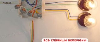
The functionality of the circuit is checked by turning on the switch. First, voltage is applied, and the lamp alternately lights up and goes out from the individual action of any of the switches. When the circuit of one of the switches is opened, the other line of the circuit is switched on.
Types and design features
To select the correct switch, it is necessary to determine the type of control movement of the handle, the tasks being solved, the connection diagram, and the properties of the connected circuits.
Household use
Switches are not used as often in everyday life as light switches, but, nevertheless, there are tasks in which it is impossible to do without them. For example, when it is necessary to control lighting from different places. Switches can be installed at the entrance to the room and near the bed (so as not to get up to turn off the light) or at different ends of a long corridor.
The implementation of such a control scheme is quite simple; its image is shown in the figure below.
Scheme for switching on lighting from two different places
Designations in the figure:
- A, B – switches;
- L – lighting device.
If it is necessary to control lighting from more places, the circuit can be slightly complicated by adding an intermediate switch.
Lighting control from three different locations
Designations in the figure:
- A, B – two-position switches;
- C – intermediate double switch of two directions;
- L1 – lighting device.
Note that using this diagram as a basis, you can control lighting from three or more places. To do this, it is enough to add the required number of intermediate switches to it; they are connected in the same way as device “C” in the diagram presented above.
Changeover switches - lighting control circuit from 3 places
But what if you want to control one lighting from three or more points. That is, there will be 3, 4, etc. switches in the circuit. It would seem that you need to take another pass-through switch and that’s it.
However, a switch with three terminals will no longer work here. Since there will be four connected wires in the junction box.
Here a changeover switch, or as it is also called a cross, cross, or intermediate switch, will come to your aid. Its key difference is that it has four outlets - two at the bottom and two at the top.
And it is installed precisely in the gap between two passageways. Find in the junction box two secondary (not main) wires from the first and second pass-through switch.
You disconnect them and connect a changeover between them. Connect the wires that come from the first to the input (follow the arrows), and those that go to the second to the output terminals.
Always check the diagram on the switches! It often happens that their entrance and exit are on the same side (top and bottom). For example, the connection diagram for a Legrand Valena changeover switch:
Naturally, there is no need to stuff the changeover itself into the junction box. It is enough to lead the ends of a 4-core cable from it there. Meanwhile, you place the switch itself in any convenient place - near the bed, in the middle of a long corridor, etc. You can turn the light on and off from anywhere.
We recommend reading: Total power of a transformer: what is it, what parts does it consist of, calculation method
The most important advantage of this circuit is that it can be changed indefinitely and add as many changeover switches as you like. That is, there will always be two passing ones (at the beginning and the end), and in the interval between them there will be 4, 5 or at least 10 crossover ones.