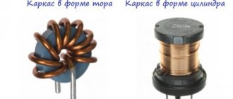
In practice, there is a fairly wide variety of electrical energy converters, both in terms of design features and operating principles. Among the devices for changing the voltage, there are armored, rod and toroidal transformers. The latter option is shaped like a donut, making it the most effective in terms of magnetic flux transmission. Its efficiency can approach 100% and is quite easy to wind, so many radio amateurs try to make a toroidal transformer with their own hands.
Design and operating principle
The design feature of such a transformer lies in the shape of the magnetic circuit, which represents a closed ring, called a torus.
Otherwise, the composition of its elements is identical to other types of electrical machines:
- Winding - made with a copper conductor, divided into primary and secondary. Both windings may differ in conductor cross-section.
- Toroidal core - has the shape of a ring, is made by typesetting, strip steel or monolithic iron, depending on the dimensions and purpose. The material used is ferromagnetic alloys, which provide good magnetic conductivity.
- Insulating materials - part of the dielectric is pre-applied to the installation wires, the rest of the dielectric is separated by the torus coil with the iron, the windings among themselves, between the coils and the casing. Tape or varnished fabric materials, electrical insulating cardboard, glue, etc. are used as insulation.
- Protective casing - designed both to protect the power transformer from mechanical damage and to prevent human contact with the surface of the windings.
- Conclusions of the secondary and network windings , fasteners and auxiliary parts.
Rice.
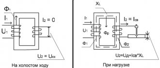
1. Design of a toroidal transformer The principle of operation of a toroidal transformer is to supply voltage to the terminals of the primary winding. After which an electric current begins to flow in it, which creates a magnetic flux inside the turns. The magnetic flux moves inside the coil frames and induces an emf in the secondary winding. If a load is connected to its terminals, the specified power will be consumed.
This device has found application in toroidal autotransformers (LATRs), radio electronics, welding transformers and other converters. At home, they rewind this type of transformer through a relatively simple process.
Selection and production of a toroidal core
The best material for the manufacture of a toroidal magnetic core is transformer strip steel. To make the core, this tape is rolled into a roll shaped like a torus of rectangular cross-section. If there is such a tape or a core made from it, then there will be no special problems in the manufacture of a magnetic core for a toroidal transformer.
Characteristics of welding transformers.
If the internal diameter d is small, you can unwind part of the tape from the inside of the torus, and then wind it on the outer surface of the core. As a result, both diameters will increase, and the area of the internal part of the magnetic circuit will increase. True, the cross-sectional area of the core S0 will decrease somewhat. If necessary, you can add tape from another magnetic circuit.
A good ready-made toroidal core can be taken from a laboratory autotransformer LATR 1M designed for a current of 9 A. You just need to rewind its windings. It happens that the stator magnetic circuit of a suitable electric motor is used to make a toroidal core for a transformer.
Another way to manufacture a toroidal core is to use plates from a faulty powerful industrial or power transformer, which at one time powered a tube color TV, as a material. First, a hoop with a diameter of about 26 cm is made from these plates using rivets. Then, inside this hoop, they begin to insert the plates end-to-end, one after another, holding them with your hand from unwinding.
After setting the required cross-section S0, the magnetic circuit is ready. To increase S0, two toroids of the same size can be made and then joined together. The edges of the toroids should be slightly rounded using a file. Two rings should be made from electrical insulating cardboard, having an internal diameter d and an external diameter D, as well as two strips on the inner and outer sides of the torus. After placing them on the toroid, the core is wrapped over the cardboard spacers with keeper or woven insulating tape. The magnetic core is ready, and you can start winding the windings.
DIY making
To make a toroidal electric machine, you need to decide on its type. In total, there are step-up and step-down transformers, in the first case, from low voltage, for example, 220V, you get high - 600V, and in the second, from high voltage, low, as the most common option, from 220V - 12V. An important parameter for the manufacture and calculation of a toroidal unit is the transformation ratio, which shows how many times the electrical quantity changes in the secondary winding in relation to the primary. To determine it, one of the following relationships is used:
U1/U2 = W1/W2 = I2/I1 = n
U1 and U2, I1 and I2 are the magnitude of voltage and current in the windings, W1 and W2 are the number of turns.
What is needed for the job?
You will definitely need a set of plumbing tools for basic work: screwdrivers, pliers, pliers, knives, soldering iron, riveter, etc. Also, in order to wind a toroidal network transformer or a homemade welding unit, you will need some materials:
- Copper wire with varnish coating - you can take it with vinyl insulation, but it will be thicker. As a result, winding will require a lot of effort, which is not very convenient with a large number of turns.
- Winding device - most often either an automated ring release mechanism or a shuttle reel is used. The first allows you to wind wires quickly and without extra effort, but purchasing it or making it yourself requires additional costs. The second method is much simpler, but it is less applicable for large cross-section conductors.
- Insulating material - you will need electrical insulating cardboard, polymer dielectric, varnished fabric insulation, fabric insulating tape. To rewind a transformer, you can not use all of the above materials, but select some of them.
- Magnetic core or torus - the best option would be a ready-made factory round core from another transformer. However, if it is not there, you can assemble the toroidal structure yourself. For this purpose, mixing from a core magnetic circuit is suitable.
Take a long sheet of steel and bend it into a ring, fixing the ends at the edge.
Rice. 2. Bend the iron plate
Place the next one inside the resulting toroidal sheet, making sure that the edges lie end to end. If necessary, the edges can be trimmed, which is especially important on the inner layers. Each plate must be clearly crimped so that when wound, the torus is tight without gaps.
If you decide to make a core, its edges should be treated with epoxy glue on both sides. After this, the core assembly can be considered complete. In addition, you can use strip steel, which is twisted tightly in a spiral using the same technology.
Rice. 3. Wind the strip steel core
Calculation
To start calculations, you need to decide on the voltage on the secondary and primary windings and the required power of the toroidal transformer. Next you will need to determine the cross section of the torus:
S = H * ((Dd))/2
Where
- S – cross-sectional area of the magnetic circuit;
- H – height of the toroidal core;
- D – outer diameter of the toroidal core;
- d – internal diameter of the toroidal core.
To calculate the number of turns, use two expressions for the transmission coefficient of the magnetic circuit:
k = f/S and W1= k*U1
Here k is the transmission coefficient, f is the frequency in the connected network, S is the cross-sectional area of the magnetic core. W1 is the number of turns in the primary coil, U1 is the voltage in the primary. From the second formula you will find out the number of turns; the turns for the secondary winding of a toroidal transformer are calculated in a similar way.
To determine the wire cross-section of the converter coils, use the formula:
S = (ρ*l * P)/U2
- S – cross-sectional area of the transformer conductor;
- P – power of the toroidal transformer;
- ρ – specific conductivity of the core material (for copper 0.017 Ohm*mm2/m);
- U – voltage in the corresponding winding of the transformer;
- l is the length of the conductor in the coil, this parameter can be found from the following formula:
l = (2 * (Dd) + 2*H)*W
Both the length and cross-section of the transformer can be calculated for each winding separately. After the calculation of the toroidal unit is ready, you can proceed to its winding.
Winding
The process of making a homemade transformer will consist of several stages:
- inspect the toroidal magnetic circuit for the absence of burrs and irregularities - the surface should be smooth, without protruding edges.
Rice. 4. Inspect the core
- make insulation from electrical cardboard for the plates of a homemade transformer; if it is not available, you can take any other dielectric;
Figure 5: Insulate the core with cardboard
- to avoid damaging the wire insulation, place a vinyl tube on the edge of the shuttle and wind the copper wire;
Rice. 6. Vinyl insulation on the edge of the shuttle
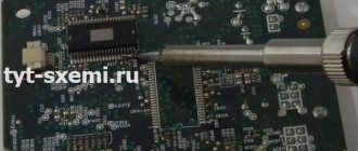
- solder the edge of the wire to the first terminal of the winding of the toroidal transformer;
Rice. 7. Solder the wire to the transformer terminal
- insulate with electrical insulating cardboard and secure the soldering area to the core;
Rice. 8. Secure the soldering point to the core
- use a shuttle to wind the winding, while trying to make turns as close to the core as possible;
Rice. 9. Wind the winding with a shuttle
- insulate the primary winding of the toroidal transformer.
Rice.
10. Insulate the primary winding Rewinding the secondary winding is carried out in a similar way, after which it is also insulated and the entire structure, if necessary, is covered with a housing. The toroidal transformer is ready.
Winding method for toroidal transformers
Fedotov Alexey Gennadievich (UA3VFS) Gus-Khrustalny
The winding technology and the insulation method are actually very simple and in no case involve any kind of winding, varnished fabric, or anything else. The fact is that with any winding with varnished cloth or other insulators, the internal window of the TORA is instantly filled, since on the outside there is one layer, and on the inside there are 5-10 layers, and even uneven ones. I have long been planning to write an article about a method for high-quality winding of tori. This takes quite a long time to explain and is better shown in the photo. Moreover, after winding, the windings do not turn into a wheel, and the transformer itself does not become egg-shaped and wire consumption is minimal. In view of all this, the efficiency of the transformer is maximum. And what comes out of this, you can see in my
.
Let me make a reservation right away: we are talking about powerful toroidal transformers. Overall power, which is more than 500W. Which are wound with wires from 1 to 3mm. naturally turn to turn. And, as a rule, the network winding of which lies in the range from 100 to 400 turns, in total, that is, 0.5-2 turns per volt. Winding less powerful transformers in this way is troublesome, but it is possible if desired.
What is needed for winding.
1) You need to make a stand for winding the toroid; this is done very simply. Take a square piece of chipboard or plywood 10-15mm thick. With dimensions of 200X200mm, we also need two wooden blocks 200mm long and 20X20mm square. We need to either glue these two bars in the center of our site, parallel to each other, with a distance of 100mm between them. It’s even better to screw these bars to the platform using screws, but with countersunk heads and recess the heads into the plywood, otherwise they will scratch the table. Now if you put a toroid on this stand, it will stand firmly and steadily. 2) You need a shuttle, I cut the shuttle out of plexiglass 5-6mm thick. The width is usually 30-40mm. length 300-400mm. I make the end cuts not at an angle, but in a semicircle and process them with a file so that the insulation of the wire does not deteriorate, and I even glue one or two strips of electrical tape, again to protect the wire. We wind the wire onto the shuttle; it’s okay if there isn’t enough wire, you can carefully solder the wire and wind it further. But it’s better to calculate it so that there is enough wire. 3) Now we need material for insulation between the layers, it’s very simple, you just need to find thin cardboard (packaging), for example, I use speaker boxes for cars. The main thing is that it is not a thick, but not thin material, the thickness of the cardboard is about 0.5 mm. If it is glossy on one side, then that is also good. 4) We also need thick threads, number 10-20. But at worst, number 40 is possible. The winding itself is carried out away from you to the right.
And now the most important thing is the manufacture of the insulating gaskets themselves between the layers. We will need a caliper with sharp ends
.
We measure the outer diameter of our torus
and add 20mm.
(for overlap) and divide in half. For example, the outer diameter of the torus is 150mm + 20mm = 170mm. 170mm./2 = 85mm. We set the bar to 85mm. and fix it with a screw. We will use the rod itself as a compass for drawing circles on cardboard. Why use a barbell and not a regular compass, which is both easier and more convenient? And everything is very simple, when we draw on the cardboard with the sharp and durable end of the rod, a depressed groove will remain on the cardboard and it will help us. This groove is very useful for making it easier to bend the inner cut circle of our gaskets. In general, you yourself will understand that a barbell is better than a convenient compass. And so we draw the outer circle on the cardboard and cut it out with scissors; in principle, the outer circle can be drawn with an ordinary compass. Next, we measure the internal diameter of the torus
, do not add or subtract anything, but simply divide it in half. For example, diameter 60mm/2 = 30mm. We set the caliper caliper to 30mm. fix it with a screw and draw the internal diameter on cardboard. Next, we take a pencil and a ruler and work on the inner circle, first we draw a cross, that is, we divide the circle into 4 parts, then into 8 parts, if the inner diameter of the TOR is more than 60mm. then also into 16 parts. >Next, we draw another circle with a regular compass, which is half the size of the inner one, that is, we move the compass apart by 15mm.
And now we need a flat piece of plywood or chipboard on which we will place our cardboard blank for cutting through our parts drawn in pencil with the end of a sharp scalpel or knife. You need to cut in a circle from the outer edge of the circle to the central point, no further, otherwise the cardboard will ride up. You need to cut right through the cardboard. Next, using scissors, we cut out the inner circle we drew with a regular compass. Bend the resulting slices perpendicular to the workpiece. It is clear that two such blanks are needed for each layer; each time the diameters are measured again, since their value changes from layer to layer.
Next, measure the height of the torus and cut out two strips of cardboard of the same width. We insert one strip inside the torus, so that the overlap is no more than 10mm. We wind the second strip in one layer onto the outer side of the torus with the same overlap. We put both round blanks on the ends of the torus, fasten them with thread in three or four places in a circle. And then we begin to wind.
The most dangerous places for breakdown are the external and especially internal corners of the TOR circles. Therefore, if during winding we see that the wire can come into contact with the wire of the inner layer, especially along the inner corner of the TORA circle. Then you need to place strips of the same cardboard 10mm wide under the wire. and 20-30mm long, where necessary. On the outer side, as a rule, this does not have to be done, since the outer side of the workpiece is layered on the edge and well protects the wire from short-circuiting.
All marking and cutting of cardboard blanks is done on the matte side of the cardboard,
It is not advisable to use glossy cardboard on both sides.
Before you start winding the torus, you need to wrap two layers of electrical tape on your fingers on both bends of the little finger and on the bend of the index finger, otherwise there will be huge water calluses.
Many people are interested in how to calculate TOP.
The fact is that the number of turns will depend on the quality of the iron, but the approximate calculation is done simply, like with a conventional transformer, we only take a coefficient of 20-30. Well, for example, we measure the height, it = 10cm. We measure the wall thickness, it = 5 cm. 10x5 = 50cm. 25/50=0.5 turns per 1 volt. 220x0.5=110 turns of the network winding. Now we begin to wind the network winding, having wound approximately 90 turns, we try to connect it to the network, while measuring the no-load current. It is not at all difficult to connect the tip of the wire directly to the shuttle. Gradually winding the wire, we bring the no-load current to 50-100mA. and at this point we stop winding, the resulting number of turns will be realistic. Now we divide this real number by 220 and get the real value of the number of turns per 1 volt. And in accordance with this figure we calculate all output windings.
Keep in mind that when the transformer is connected to the network, the initial instantaneous current surge is very large. And in order not to burn the tester, you need to do this. We connect the network cable through a closed toggle switch parallel to the toggle switch, turn on the tester, plug the plug into the socket and only then open the toggle switch to see the no-load current.
By the way, it is precisely because of the powerful primary inrush current that transformers with a power of more than 1 kW must be turned on using a soft switching circuit. Moreover, this scheme is very simple.
Illustrations
November 20, 2005 ua3vfs (at) mail.ru https://ua3vfs.narod.ru