Universal Serial Bus or USB is a hardware-type interface that allows peripheral equipment (digital cameras and players, computer keyboards and mice, MFPs, etc.) to synchronize with the host to interact with a PC. Its pinout describes the design of the connectors, indicating the location of the contacts. Its main advantage is the ability to connect and disconnect peripherals without rebooting the computer.
Types of USB connectors and differences
USB is an input/output interface that eliminates the clutter associated with various peripherals that have come out in recent times. USB only recognizes one type of connector for all devices, so mixing it up is impossible. Unfortunately, in practice there are different types of connectors. And even with USB Type-C connectors, you can’t immediately tell what capabilities the cables support.
Two important aspects of usb are support capabilities and overall bandwidth. The technology supports the mode of 127 information devices and has a total throughput of at least 12 Mbit per second. Depending on the speed, there are four versions of connectors:
- 1.1 (12 or more Mbps): universal in terms of support for USB hubs, but rarely used today.
- 2.0 (480 Mbps): currently the most common and popular;
- 3.0 (5 Gbps or more): advanced specification providing fast downloads.
- 3.1 and higher (10 Gbps or more): the latest development, quite rare.
When new versions of interfaces appear, their backward compatibility is maintained - for example, 3.0 can be connected to 2.0, but not vice versa. Despite the versatility of the serial bus, there are 2 types of it:
- a socket installed on a host or device, also known as a port or socket;
- a plug attached to a cord and called a plug.
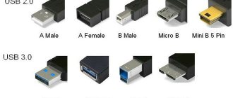
The variety of USB connectors has increased in parallel with the development of specifications. Initially, there were only mandatory standards A and B. The connectors were different, so users could not connect one to the other. Later, Method C was introduced, designed to provide a connection that was more powerful and reliable than the previous version, with increased data transfer and synchronization speeds than the first version.
Today there are the following:
| A | IN | AB | WITH |
| 2.0A | 2.0B | Micro AB | C Type (up to 10 Gbit) |
| 2.0 Micro A | 2.0 Micro B | ||
| 3.0A | mini-B (5 pin) | ||
| Mini-B (4 pin) | |||
| 3.0B | |||
| 3.0 Micro B |
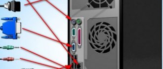
Type A
Type A, found on computers and laptops, as well as on removable memory cards and many other equipment. Its scope of application is “downstream” connections to network hubs and host controllers. This is a large flat rectangular connector, the connection to which is made through a tight insert.
Type B
Another type of connector, designated B, is intended for small peripheral equipment. Externally, it has an almost regular square shape, with neat roundings at the upper corners.
Mini USB connector
USB and mini-USB are fully compatible with each other. Therefore, they can be connected using a simple adapter. Mini USB ports are mostly found on very small devices such as cameras or cell phones.
USB Mini is designed to connect modern slim mobile phones and tablets to PCs and laptops. The Mini A and B versions are equally widespread. They provide connection for miniature gadgets, and the reliability of the connection involves a construct with a special fastener.
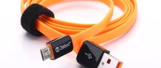
USB micro connector
As mobile gadgets become thinner and more compact, an extremely small format, USB Micro, was developed. It exists in A and B formats, as well as an AB port.
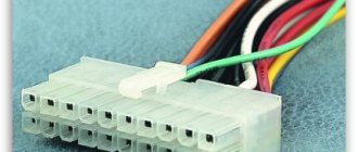
Pinout diagram
Assignment of micro-USB connector contacts - socket and plug
The USB (Universal Serial Bus) connector is a universal-purpose serial bus, the most common wired method of connecting external devices to a computer. This connector allows you to organize data exchange between a computer and a video camera, card reader, MP3 player, external hard drive, or smartphone.
USB pinout
2.0 connectors types a and b
Connector A is called active. Its plug has an elongated rectangular cross-section that fits into socket A on the downstream port of a hub or host and transmits both power and data. It is used on flash drives, keyboards, mice, etc.
Connector B is considered passive. Its plug has a square cross-section with beveled top outer corners, and is used to connect to jack B of printers, scanners, etc. In some cases, jack B has no data connections and is used solely to supply power from the upstream device.
For this reason, a USB connection requires a cable with connectors of both types. However, the pinout of connectors A and B of version 2.0 is almost identical. Both consist of 4 contacts (2 each on top and bottom) with identical functionality.
Pin assignment usb 2 0
The pinout of different USB connectors demonstrates their identity. The version 2.0 connector design uses 2 wires for power and 2 for data signals.
| Contact | Color | Functional |
| 1 | red | power supply (4.75 - 5.25 V) |
| 2 | white | sending |
| 3 | green | reception channel |
| 4 | black | zero potential and grounding |
| Shell Shield | does not have insulation of any color | contact with shielding task |
The pinout of USB A and B does not differ at all in the diagram, and the purpose of the connected contacts is as follows:
- No. 1 – determines the voltage source (+ VDD) supplied to the connected equipment, and also serves as an indicator of the connection confirmation signal.
- No. 2 (-D) is used to send data, together with pin No. 3 (+D) used to enter it. The purpose of these contacts is to exchange information in the format established by the USB protocol.
- No. 4 for grounding.
The connector diagram for usb 2 0 consists of 4 pins and is relatively easy to use. Two wires are used to provide VBUS (VCC) and ground. The voltage for the VCC supply is +5V and is usually supplied from the microcontroller itself. Contact C is connected to C of the microcontroller.
The other two wires are D+ and D-. They should be connected to the D+ and D- pins of the host respectively. They also require a pull-down resistor of 15k each.
3.0 types a and b
For USB 3.0 connector type A and B, the pinout consists of 9-10 pins. In addition to the elements included in 2.0, two additional differential pairs (four wires, SSTx+, SSTx−, SSRx+ and SSRx−) have been added to provide high-speed, full-duplex communication.
| Contact | Name | Functional |
| 1 | VDD | DC electricity point |
| 2 | D- | data transfer |
| 3 | D+ | differential data reception |
| 4 | ID N/C | OTG identification (not connected or used for grounding) |
| 5 | GND | applied to GND |
| 6 | SSTx- | high-speed output |
| 7 | SSTx+ | high-speed reception |
| 8 | used for grounding | |
| 9 | SSRx | high-speed output |
| 10 | SSRx- | high-speed reception |
The USB 3.0 pinout is a combination of the 2.0 circuit and 5 added pins with other functionality for connecting high-speed external drives.
micro-usb connector
The pinout of Micro-USB, which has a 4-pin structure, corresponds to A and B. But in the version with 5 pins there are some differences:
| Contact | Signal name |
| 1 | power supply |
| 2 | output information |
| 3 | input information |
| 4 | Most of the time it doesn't connect |
| 5 | Earth |
| Shell Shield | shielding |
The Micro USB connector is often used to charge mobile phones and operate other portable equipment (batteries, wireless headsets and speakers). Some electronics manufacturers have begun to follow their own standards, in which no data is exchanged and the corresponding contacts are not active.
The pinout of the Micro USB connector, designed for charging smartphones and small equipment, has the following features:
- Contact No. 1 - power supply (+ 5V);
- No. 2 and No. 3 exchange data (output and input). May not be connected (if data transfer is prohibited);
- No. 4 (ID) are used to identify devices, especially for the ability to create OTG connections;
- No. 5 – will not be connected, because grounding will be provided by contact No. 4.
mini-usb
Mini USB is a form of USB technology that uses smaller, smaller connectors. Suitable for small household appliances (smartphones, digital players and PDAs). The Mini USB pinout can consist of 4 or 5 wires.
The version with 4 components is similar to connectors A and B (VBUS, D-, D+, GND), with 5 - identical to Micro USB.
Pinout diagram
Assignment of micro-USB connector contacts - socket and plug
The USB (Universal Serial Bus) connector is a universal-purpose serial bus, the most common wired method of connecting external devices to a computer. This connector allows you to organize data exchange between a computer and a video camera, card reader, MP3 player, external hard drive, or smartphone.
Length of cable
The maximum cable length should not exceed 5 meters. The cable length can be increased to 30 meters if the active component (hub, etc.) is installed every 5 meters. The signal propagation time between the end device and the host is too long. Host (PC connection) provides a maximum current of 500mA at 5V operating voltage or 900mA with USB 3.0.
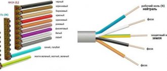
The usual pinout of the internal wires of a USB cable by color:
- Red: A contact that carries positively charged electrical energy. Additionally, it has a 5 volt DC charge.
- Black: ground wire.
- White: positive wire for information.
- Green: negative for information.
If the wiring inside the cord is a combination of other shades:
- Orange: Has the same functionality as the red wire (5 volts DC through which a positive charge passes).
- White: in this version, the USB cable is grounding.
- Green: data transfer plus.
- Blue: data transmission minus.
If the cable uses completely different colors, you should study the instructions from the manufacturer.
FAQ
What is the micro USB pinout?
For USB 2.0 type, wires are used. Red and black for power, white and green for data.
Why does micro USB have 5 pins?
The connector was designed with five pins. Typically only 2 or 4 pins are used. Some manufacturers use pin 5 for video or other purposes.
What are the positive and negative wires on the micro USB?
The red wire is positive and the black wire is negative.
Is it possible to connect black and red wires?
There is always a black and a red wire in one cable. In this case, both wires are connected to different connectors. Connecting the wires is not permissible, as it will lead to a short circuit.
Does the red wire go to the white or to the black?
The red wire is usually paired with a black wire.
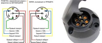
What color wire goes to L and N?
Phase - L, usually brown or red. N - zero, blue or black wire.
How to connect two small electrical wires?
The best option is to crimp them with a crimper or solder them together. Twisting the cable is unreliable and also short-lived.
How to connect USB for power only?
It is enough to use 2 lines in the cable - plus and minus, red and black wire.
How to resolder a USB plug?
It is necessary to re-solder the wires or crimp them in the required sequence.
How to connect a 4-wire light bulb?
It is necessary to connect each wire of the lamp to the corresponding connector in accordance with the color markings.
What is the difference between 2 wire and 4 wire?
The more wires, the more possibilities such a cable offers. For example, more power phases or 2 power phases and grounding. The USB cable has 2 wires that only provide power. With four wires, such a cable allows you to transfer data and power the connected device with energy.
What color is the neutral wire?
This cable is usually blue insulated.
Does the neutral wire have power?
No, this cable is used to complete the circuit. However, you should not touch such a wire with unprotected hands.
What are D+ and D in USB?
D+ and D- are used for data transmission.
How many pins does USB 3 have?
Total 9 pins in USB-A. 4 standard contacts and 5 additional ones.
How many pins does USB 2.0 have?
Usually 4 contacts. 2 pins are used for data transfer and 2 pins for power. Some connector types contain an additional fifth pin. The additional contact is rarely used, for example for video transmission or for restoring and flashing the device.
How to connect 12V to USB?
You need to connect the 12V wires to the corresponding pins on the USB.
What are the red black white and green wires?
The red cable is always responsible for power. The black cable is ground to complete the circuit. The white and green wire are used for data transmission.
How to connect 4 wires to 2 wires?
Only the corresponding wires should be connected to the two wires. The remaining wires should be insulated.
What do the pink and white wires mean?
The pink and white wire are often responsible for data transmission. Typically a combination of white and green is used. And the color difference is usually due to the lack of a wire of a suitable color. Or a wire of a different color is cheaper than a standard color.
Which USB pin is power?
Contact with connected red wire.
Pinout of connectors on
Plug
When looking at pinout diagrams, you need to understand all the markings present on it.
Standard marks:
- Connector type – active or passive (i.e. A or B).
- The connection format is a female socket (port, M) or a male socket (plug, F).
- Size format – standard, Microusb or Mini.
According to the color scheme, the contacts should be located in the direction from left to right:
- red – positive, with a maximum DC layer of 500 ml-amp;
- white and green – data- and data+;
- black – “minus” or “ground”.
MicroUSB and Mini differ in the following pin arrangement:
- red, white and green - no differences;
- ID - in connector B it will not be active and connected, in A it will need to be shorted to the black ground contact.